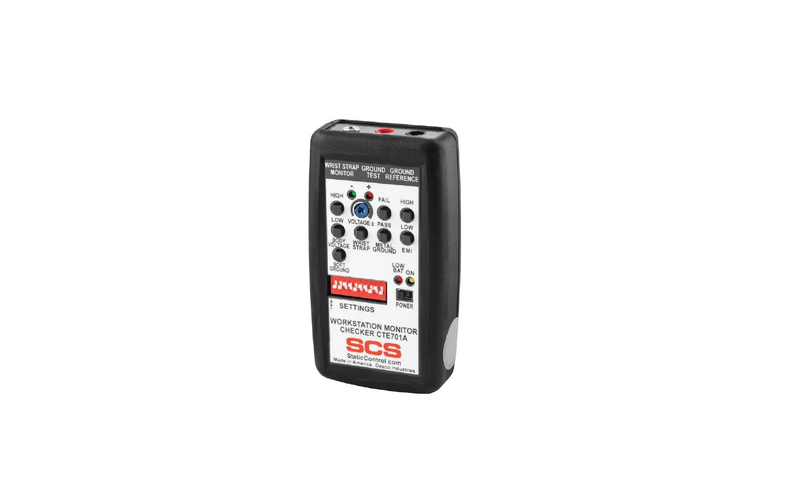
SCS CTE701 Verification Tester for Continuous Monitors
Description
The SCS CTE701 Verification Tester is used to perform periodic test limit verification of the SCS WS Aware Monitor, Ground Master Monitor, Iron Man® Plus Monitor, and Ground Man Plus Monitor. Verification may be accomplished without removing the monitor from its workstation. The Verification Tester is National Institute of Standards and Technology (NIST) traceable. The frequency of verification is based on the critical nature of the ESD-susceptible items handled. SCS recommends the annual calibration of workstation monitors and the CTE701 Verification Tester. The CTE701 Verification Tester meets ANSI/ESD S20.20 and Compliance Verification ESD TR53.
The SCS CTE701 Verification Tester can be used with the following items:
| Item | Description |
| 770067 | WS Aware Monitor |
| 770068 | WS Aware Monitor |
| CTC061-3-242-WW | WS Aware Monitor |
| CTC061-RT-242-WW | WS Aware Monitor |
| CTC062-RT-242-WW | WS Aware Monitor |
| 770044 | Ground Master Monitor |
| CTC331-WW | Iron Man® Plus Monitor |
| CTC334-WW | Ground Man Plus Monitor |
| CTC337-WW | Wrist Strap and Ground Monitor |
| 773 | Wrist Strap and Ground Monitor |
Packaging
- 1 CTE701 Verification Tester
- 1 Black Alligator-to-Banana Test Lead, 3 ft.
- 1 Red Mini Grabber-to-Banana Test Lead, 3 ft.
- 1 Black 3.5 mm Mono Cable, 2 ft.
- 1 9V Alkaline Battery
- 1 Certificate of Calibration
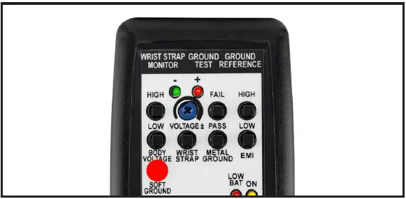
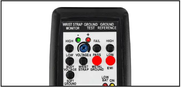
Features and Components
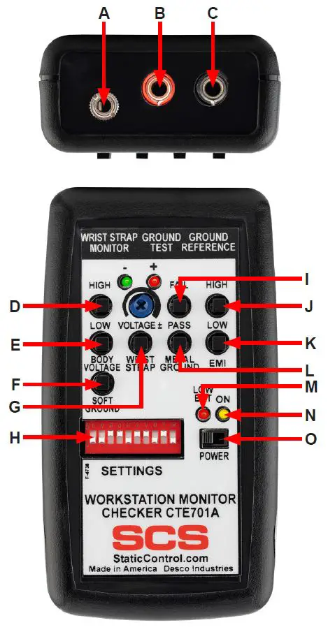
- A. Operator Dual-wire Jack: Connect one end of the included 3.5 mm mono cable here, and the other end into the monitor’s operator jack.
- B. Soft/Metal Ground Banana Jack: Connect the banana plug terminal of the red test lead here, and the other end to the monitor’s mat or tool ground circuit.
- C. Reference Ground Banana Jack: Connect the banana plug terminal of the black test lead here, and the other end to the equipment ground.
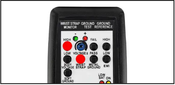
- D. High Body Voltage Test Switch: Simulates a BODY VOLTAGE FAIL condition on the monitor’s operator circuit when pressed.
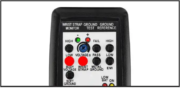
- E. Low Body Voltage Low Test Switch: Simulates a BODY VOLTAGE PASS condition on the monitor’s operator circuit when pressed.
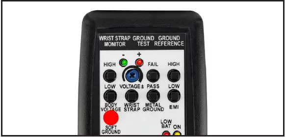
- F. Soft Ground Test Switch: Simulates a MAT PASS condition on the monitor when pressed.
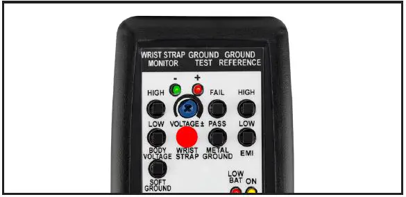
- G. Wrist Strap Test Switch: Simulates an OPERATOR PASS condition on the monitor when pressed.
- H. Test Limit DIP Switch: Configures the test limits on the CTE701 Verification Tester.
- I. High Metal Ground Test Switch: Simulates a TOOL FAIL condition on the monitor when pressed.
- J. High EMI Test Switch: Simulates an EMI FAIL condition on the monitor’s tool circuit when pressed.
- K. Low EMI Test Switch: Simulates an EMI PASS condition on the monitor’s tool circuit when pressed.
- L. Low Metal Ground Test Switch: Simulates a TOOL PASS condition on the monitor when pressed.
- M. Low Battery LED: Illuminates when the battery needs to be replaced.
- N. Power LED: Illuminates when the CTE701 Verification Tester is powered.
- O. Power Switch: Slide to the left to power the Verification Tester OFF. Slide to the right to power the Verification Tester ON.
Installation
The CTE701 Verification Tester’s 10-position DIP switch is used to configure its test limits for soft ground, metal ground, EMI, and operator.
Soft Ground
The soft ground resistance is configured with switches 1-4. Pressing the SOFT GROUND pushbutton will result in a load with slightly lower resistance than the test limit.
| Test Limit | Switch | |||
| 1 | 2 | 3 | 4 | |
| 1 gigohm | OFF | OFF | OFF | ON |
| 400 megohms | OFF | OFF | ON | ON |
| 100 megohms | OFF | ON | ON | ON |
| 10 megohms | ON | ON | ON | ON |
Metal Ground
The metal ground impedance is configured with switches 5-8. Pressing the HIGH METAL GROUND pushbutton will load 1 ohm higher than the configured test limit. Pressing the PASS METAL GROUND pushbutton will load 1 ohm less than the test limit. For example, if the monitor to be checked is set to 10 ohms, the Verification Tester will verify that it passes at 9 ohms and fails at 11 ohms.
| Test Limit | Switch | |||
| 5 | 6 | 7 | 8 | |
| 1 ohm | ON | ON | ON | ON |
| 2 ohms | OFF | ON | ON | ON |
| 3 ohms | ON | OFF | ON | ON |
| 4 ohms | OFF | OFF | ON | ON |
| 5 ohms | ON | ON | OFF | ON |
| 6 ohms | OFF | ON | OFF | ON |
| 7 ohms | ON | OFF | OFF | ON |
| 8 ohms | OFF | OFF | OFF | ON |
| 9 ohms | ON | ON | ON | OFF |
| 10 ohms | OFF | ON | ON | OFF |
| 11 ohms | ON | OFF | ON | OFF |
| 12 ohms | OFF | OFF | ON | OFF |
| 13 ohms | ON | ON | OFF | OFF |
| 14 ohms | OFF | ON | OFF | OFF |
| 15 ohms | ON | OFF | OFF | OFF |
| 16 ohms | OFF | OFF | OFF | OFF |
EMI
The EMI high-frequency signal is configured with switch 9. The CTE701 Verification Tester provides two different levels of high-frequency signal: elevated and normal. Pressing the HIGH EMI pushbutton will load a high signal level within its range. Pressing the LOW EMI pushbutton will load a low signal within its range.
| Signal Level | Switch |
| 9 | |
| Elevated | ON |
| Normal | OFF |
Wrist Strap
The wrist strap resistance is configured with switch 10. The CTE701 Verification Tester provides resistance of a certain value across the wrist strap terminal input in order to simulate a wrist strap. A good quality dual-wire wrist cord has a 1 megohm resistor in each of its conductors. The Verification Tester is designed to simulate dual-wire wrist straps with and without resistors. The 12 megohms setting simulates a wrist strap with two 1 megohm resistors in series.
| Test Limit | Switch |
| 10 | |
| 12 megohms | OFF |
| 10 megohms | ON |
Operation
Iron Man® Plus Workstation Monitor
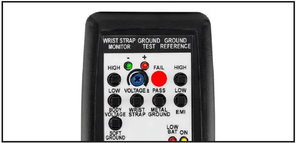
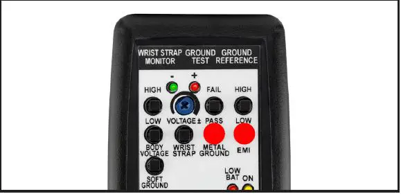
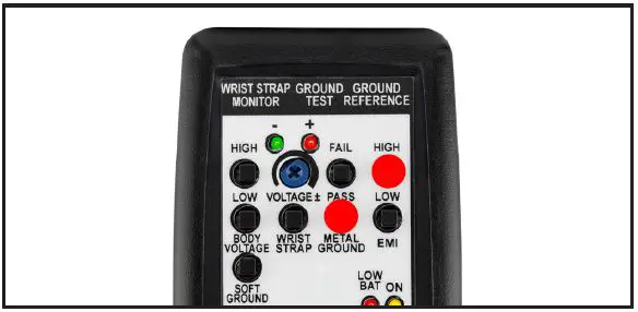
CONFIGURING THE VERIFICATION TESTER Configure the Verification Tester’s DIP switch to the settings shown below. This will make its test limits match the factory default limits of the monitor.
VERIFYING THE OPERATOR CIRCUIT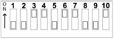
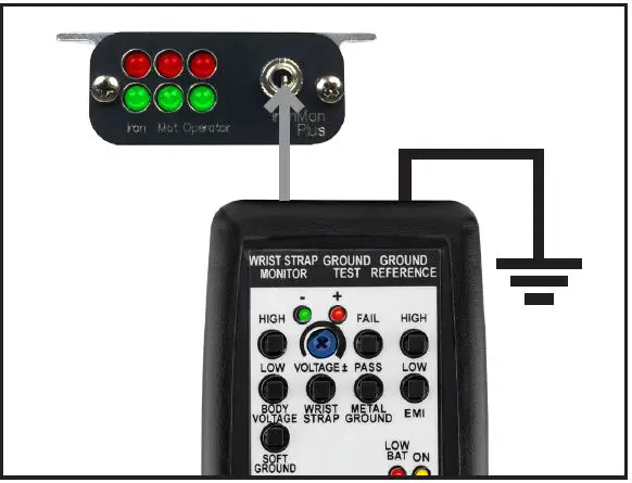
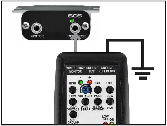
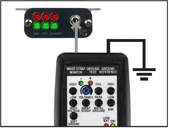
- Use the black test lead to connect the Verification Tester to equipment ground.
- Power the Verification Tester ON.
- Use the 3.5 mm mono cable to connect the Verification Tester to the monitor’s operator jack. The monitor’s operator LED will illuminate red, and its alarm will sound.

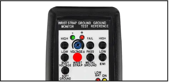
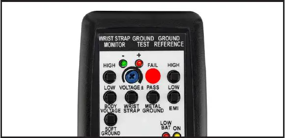
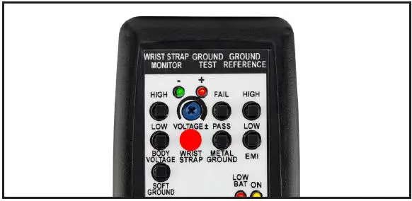
Connecting the Verification Tester to the Iron Man® Plus Workstation Monitor’s operator jack - Press and hold the Verification Tester’s WRIST STRAP test switch. The monitor’s operator LED will illuminate green, and its audible alarm will stop. This verifies the operator circuit’s impedance limit.

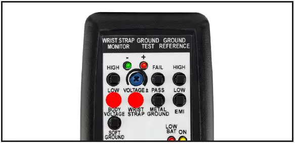
- Continue to press and hold the Verification Tester’s WRIST STRAP test switch. Simultaneously, press and hold the Verification Tester’s LOW BODY VOLTAGE test switch. The monitor’s operator LED will remain green, and no audible alarm will sound. This verifies the operator circuit’s low body voltage limit.

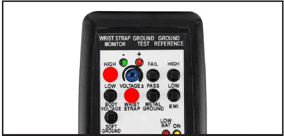
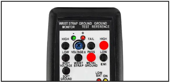
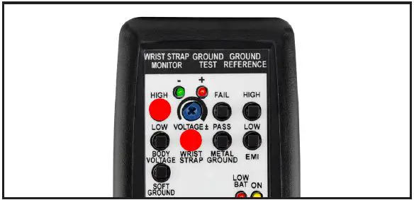
- Continue to press and hold the Verification Tester’s WRIST STRAP test switch. Simultaneously, press and hold the Verification Tester’s HIGH BODY VOLTAGE test switch. The monitor’s green operator LED will illuminate continuously, its red LED will blink, and an audible alarm will sound. This verifies the operator circuit’s high body voltage limit.

- Disconnect the mono cable from the monitor.
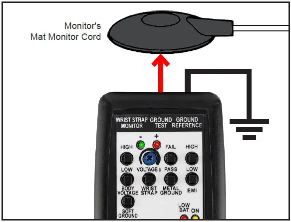
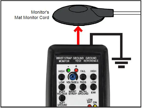
VERIFYING THE MAT CIRCUIT - Connect the red test lead to red banana jack located at the top of the Verification Tester.
- Disconnect the monitor’s white mat monitor cord from its worksurface mat and turn it over to expose its 10 mm snap.
- Clip the red test lead’s mini grabber to the 10 mm snap on the white mat monitor cord.

- Wait approximately 5 seconds for the monitor’s mat LED to illuminate red and sound its audible alarm.
- Press and hold the Verification Tester’s SOFT GROUND test switch. The monitor’s mat LED will illuminate green, and its audible alarm will stop after approximately 3 seconds. This verifies the mat circuit’s resistance limit.

- Disconnect the red test lead from the monitor’s white mat monitor cord.
- Reinstall the white mat monitor cord to the worksurface mat.
VERIFYING THE IRON CIRCUIT
Note: A variable DC power supply must be used to complete this procedure. The CTE701 Verification Tester cannot verify the iron circuit in the Iron Man® Plus Workstation Monitor. - Turn the voltage alarm trimpot at the back of the monitor fully clockwise. This configures it to ±5 V.
- Power the variable DC power supply. Configure it to 5.0 V.
- Connect the negative terminal from the variable DC power supply to ground. Connect its positive terminal to the yellow alligator cord connected to the monitor’s BOARD terminal. The monitor’s Iron LED should illuminate red and its audible alarm should sound.
- Set the variable DC power supply to 4.0 V. The monitor’s Iron LED should illuminate green and its audible alarm should stop.
- Disconnect the variable DC power supply from the monitor and ground. Connect its positive terminal to ground and its negative terminal to the monitor’s yellow alligator cord.
- Verify that the variable DC power supply is still set to 4.0 V. The monitor’s Iron LED should illuminate green.
- Set the variable DC power supply to 5.0 V. The monitor’s Iron LED should illuminate red and its audible alarm should sound.
WS Aware Monitor
CONFIGURING THE VERIFICATION TESTER
Configure the Verification Tester’s DIP switch to the settings shown below. This will make its test limits match the factory default limits of the monitor.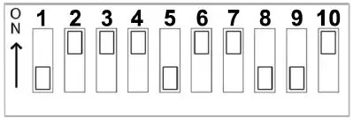
VERIFYING THE OPERATOR CIRCUIT
- Use the black test lead to connect the Verification Tester to the equipment ground.
- Power the Verification Tester ON.
- Use the 3.5 mm mono cable to connect the Verification Tester to the monitor’s operator jack. The monitor’s operator LED will illuminate red, and its alarm will sound.

- Press and hold the Verification Tester’s WRIST STRAP test switch. The monitor’s operator LED will illuminate green, and its audible alarm will stop. This verifies the operator circuit’s impedance limit.

- Continue to press and hold the Verification Tester’s WRIST STRAP test switch. Simultaneously, press and hold the Verification Tester’s LOW BODY VOLTAGE test switch. The monitor’s operator LED will remain green, and no audible alarm will sound. This verifies the operator circuit’s low body voltage limit.

- Continue to press and hold the Verification Tester’s WRIST STRAP test switch. Simultaneously, press and hold the Verification Tester’s HIGH BODY VOLTAGE test switch. The monitor’s green operator LED will illuminate continuously, its red LED will blink. This verifies the operator circuit’s high body voltage limit.
- Disconnect the mono cable from the monitor.
VERIFYING THE MAT CIRCUIT - Connect the red test lead to red banana jack located at the top of the Verification Tester.
- Disconnect the monitor’s white mat monitor cord from its worksurface mat and turn it over to expose its 10 mm snap.
- Clip the red test lead’s mini grabber to the 10 mm snap on the white mat monitor cord.

- Wait approximately 5 seconds for the monitor’s mat LED to illuminate red and sound its audible alarm.
- Press and hold the Verification Tester’s SOFT GROUND test switch. The monitor’s mat LED will illuminate green, and its audible alarm will stop after approximately 3 seconds. This verifies the mat circuit’s resistance limit.

- Disconnect the red test lead from the monitor’s white mat monitor cord.
- Reinstall the white mat monitor cord to the worksurface mat.
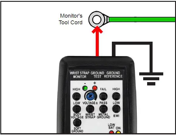
VERIFYING THE TOOL CIRCUIT - Disconnect the monitor’s tool cord from its metal tool.
- Clip the red test lead’s mini grabber to the tool cord.

- Wait for the monitor’s tool LED to illuminate red and sound its audible alarm.
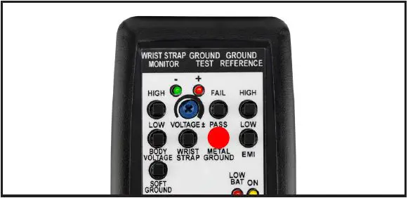
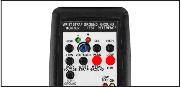
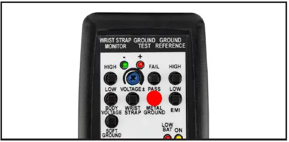
- Press and hold the Verification Tester’s METAL GROUND PASS test switch. The monitor’s tool LED will illuminate green, and its audible alarm will stop. This verifies the tool circuit’s impedance limit.
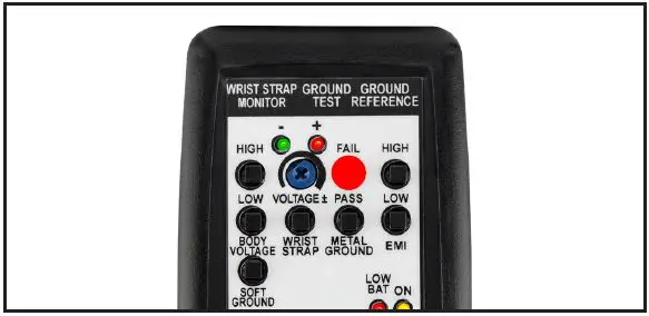
- Press and hold the Verification Tester’s METAL GROUND FAIL test switch. The monitor’s tool LED will illuminate red, and its audible alarm will sound. This verifies the tool circuit’s impedance limit.

- Press and hold the Verification Tester’s METAL GROUND PASS test switch. Simultaneously, press and hold the Verification Tester’s EMI LOW test switch. The monitor’s tool LED will remain green, and no audible alarm will sound. This verifies the operator circuit’s low EMI voltage limit.
- Press and hold the Verification Tester’s METAL GROUND PASS test switch. Simultaneously, press and hold the Verification Tester’s EMI HIGH test switch. The monitor’s tool LED will blink red, and its audible alarm will sound. This verifies the operator circuit’s high EMI voltage limit.

- Disconnect the red test lead from the monitor’s tool cord.
- Reinstall the tool cord to the metal tool.
Ground Master Monitor
CONFIGURING THE VERIFICATION TESTER
Configure the Verification Tester’s DIP switch to the settings shown below. This will make its test limits match the factory default limits of the monitor.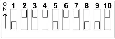
VERIFYING THE TOOL CIRCUIT
- Disconnect the monitor’s tool cord from its metal tool.
- Clip the red test lead’s mini grabber to the tool cord.
- Wait for the monitor’s tool LED to illuminate red and sound its audible alarm.
- Press and hold the Verification Tester’s METAL GROUND PASS test switch. The monitor’s tool LED will illuminate green, and its audible alarm will stop. This verifies the tool circuit’s impedance limit.
- Press and hold the Verification Tester’s METAL GROUND FAIL test switch. The monitor’s tool LED will illuminate red, and its audible alarm will sound. This verifies the tool circuit’s impedance limit.

- Press and hold the Verification Tester’s METAL GROUND PASS test switch. Simultaneously, press and hold the Verification Tester’s EMI LOW test switch. The monitor’s tool LED will remain green, and no audible alarm will sound. This verifies the operator circuit’s low EMI voltage limit.
- Press and hold the Verification Tester’s METAL GROUND PASS test switch. Simultaneously, press and hold the Verification Tester’s EMI HIGH test switch. The monitor’s tool LED will blink red, and its audible alarm will sound. This verifies the operator circuit’s high EMI voltage limit.

- Disconnect the red test lead from the monitor’s tool cord.
- Reinstall the tool cord to the metal tool.

Ground Man Plus Workstation Monitor
CONFIGURING THE VERIFICATION TESTER
Configure the Verification Tester’s DIP switch to the settings shown below. This will make its test limits match the factory default limits of the monitor.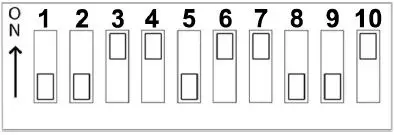
VERIFYING THE OPERATOR CIRCUIT
- Use the black test lead to connect the Verification Tester to the equipment ground.
- Power the Verification Tester ON.
- Use the 3.5 mm mono cable to connect the Verification Tester to the monitor’s operator jack. The monitor’s operator LED will illuminate red, and its alarm will sound.

- Press and hold the Verification Tester’s WRIST STRAP test switch. The monitor’s operator LED will illuminate green, and its audible alarm will stop. This verifies the operator circuit’s impedance limit.

- Continue to press and hold the Verification Tester’s WRIST STRAP test switch. Simultaneously, press and hold the Verification Tester’s LOW BODY VOLTAGE test switch. The monitor’s operator LED will remain green, and no audible alarm will sound. This verifies the operator circuit’s low body voltage limit.
- Continue to press and hold the Verification Tester’s WRIST STRAP test switch. Simultaneously, press and hold the Verification Tester’s HIGH BODY VOLTAGE test switch. The monitor’s green operator LED will illuminate continuously, its red LED will blink, and an audible alarm will sound. This verifies the operator circuit’s high body voltage limit.
- Disconnect the mono cable from the monitor.
VERIFYING THE TOOL CIRCUIT - Disconnect the monitor’s tool cord from its metal tool.
- Clip the red test lead’s mini grabber to the tool cord.
- Wait for the monitor’s tool LED to illuminate red and sound its audible alarm.
- Press and hold the Verification Tester’s METAL GROUND PASS test switch. The monitor’s tool LED will illuminate green, and its audible alarm will stop. This verifies the tool circuit’s impedance limit.

- Press and hold the Verification Tester’s METAL GROUND FAIL test switch. The monitor’s tool LED will illuminate red, and its audible alarm will sound. This verifies the tool circuit’s impedance limit.

- Press and hold the Verification Tester’s METAL GROUND PASS test switch. Simultaneously, press and hold the Verification Tester’s EMI LOW test switch. The monitor’s tool LED will remain green, and no audible alarm will sound. This verifies the operator circuit’s low EMI voltage limit.

- Press and hold the Verification Tester’s METAL GROUND PASS test switch. Simultaneously, press and hold the Verification Tester’s EMI HIGH test switch. The monitor’s tool LED will blink red, and its audible alarm will sound. This verifies the operator circuit’s high EMI voltage limit.

- Disconnect the red test lead from the monitor’s tool cord.
- Reinstall the tool cord to the metal tool.


Maintenance
Battery Replacement
Replace the battery once the Low Battery LED illuminates red. Open the compartment located on the back of the tester to replace the battery. The tester uses one 9V alkaline battery. Ensure that the battery’s polarities are oriented correctly to avoid possible circuit damage.
Specifications
| Operating Temperature | 50 to 95°F (10 to 35°C) |
| Environmental Requirements | Indoor use only at altitudes less than 6500 ft. (2 km) Maximum relative humidity of 80% up to 85°F (30°C) decreasing linearly to 50% @ 85°F (30°C) |
| Dimensions | 4.9″ L x 2.8″ W x 1.3″ H (124 mm x 71 mm x 33 mm) |
| Weight | 0.2 lbs. (0.1 kg) |
| Country of Origin | United States of America |
Warranty
Limited Warranty, Warranty Exclusions, Limit of Liability, and RMA Request Instructions
See the SCS Warranty – StaticControl.com/Limited-Warranty.aspx.
SCS – 926 JR Industrial Drive, Sanford, NC 27332
East: (919) 718-0000 | West: (909) 627-9634 • Website: StaticControl.com.
© 2022 DESCO INDUSTRIES INC Employee Owned.


