![]() Operation Manual
Operation Manual
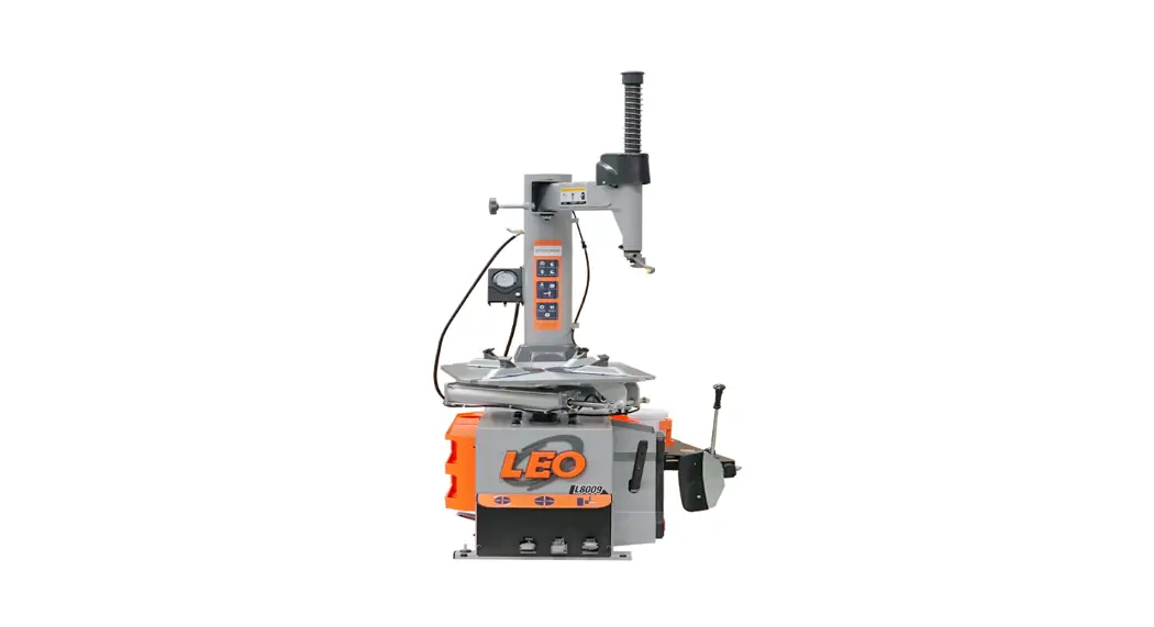
L8009
Dear customers,
Very pleased that you will purchase and use the tire changer produced by our company.
Warning
- This instruction manual is the important part of the product. Please read it carefully.
- Keep it properly in order to maintain and service.
- This machine is only applied to mount, demount and inflate the tire in the specified scope and not for any other purpose.
- The manufacturer will not be responsible for the damage arising from the improper operation.
NOTE
- This machine should be operated by the special trained qualified personnel. When operating, the unauthorized personnel will be kept far away from the machine.
- Please note the safety label stuck on the machine.
- Operators should wear safety protective facilities such as working suit, protective glasses, and eye plug and safety shoes. Keep your hands and body from the movable parts as possible as you can. Necklace, bracelet and loosen clothing may cause dangerous to the operators.
- Tire changer should be installed and fixed on the flat and solid floor. The more than 0.5m of distance from the rear and lateral side of the machine to the wall can guarantee the perfect air flow and enough operation space.
- Do not place the machine in the site of high temperature, high humidity, and dust and with flammable and corrosion gas.
- Without the permission from the manufacturer, any change on the machine parts will cause injury/damage to the machine/operator.
- Pay special attention that the tire changer should be operated under the specified voltage and air pressure.
- If you want to move the tire changer, you should under the guidance of the professional service personnel.
Safety Label Instruction
| Be sure to read all warning labels and instruction manual prior to operation of this machine. | |
| Keep hands clear of bead area when inflating. | |
| Always wear safety glasses when operating this machine. | |
| Pinch point keep hand clear. | |
| Stand clear while inflating tire. Tire of wheel failure under pressure may cause serious injury of death. | |
| Moving parts do not wear loose clothing long hair of jewelry. | |
| When breaking bead, the bead breaking blade will quickly move leftwards. | |
| Note: when press the tire, the opened clamp cylinder may injury the hand of the operator. Remember, do not touch the sidewall of the tire. | |
| Do not reach any part of your body under the demount tool. | |
| When clamping the rim, do not reach your hand or other parts of the body in between the clamp& the rim. | |
| Do not stand behind the column to avoid the column from injuring the persons when swing. | |
| Electrical shock! |
model:
rated voltage: Phase voltage hertz
factory code:
CHAPTER 1 BRIEF INTRODUCTION
1.1BRIEF INTRODUCTION
Thisseries of equipment is the tire changer with fixed column and rocker arm tire changer. It is suitable to mount, demount and inflate all types of motorcycle tire with tube &tubeless. The operation is easy, convenient, safety and reliable. It is the necessary equipment for the auto service shop and tire shop.
The machine can be equipped with the assistant to adapt to demount and mount the low profile and stiff tires.
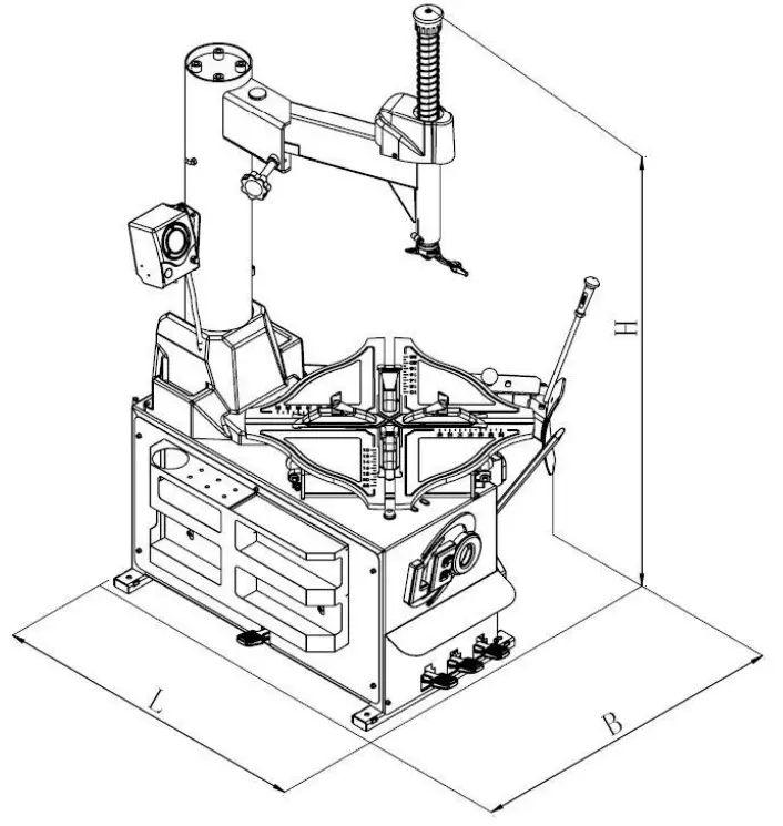
1.2EQUIPMENT OVERALL DIMENSION
| model | L | B | H | W |
| L8009 | 1200mm ( 47.2″) | 1300mm (51.2″) | 1600mm~1940mm (63″~76.4″) | 275Kg (606LB) |
1.3 TECHNICAL PARAMETER
Operation pressure:8-10bar (116~145 Psi)
motor:60Hz110V 1.1Kw (0.82HP)
turntable speed:6.5rpm
noise:<70dB(A)
1.4 APPLICATION SCOPE
| model | Max. wheel diameter | Max. wheel width | rim diameter (outer clamp) | rim diameter (inner clamp) |
| L8009 | 1250mm(49″) | 3”-13″ | 11″~24″ | 13″~26″ |
Note: can adopt the adjustable turntable like picture 1.
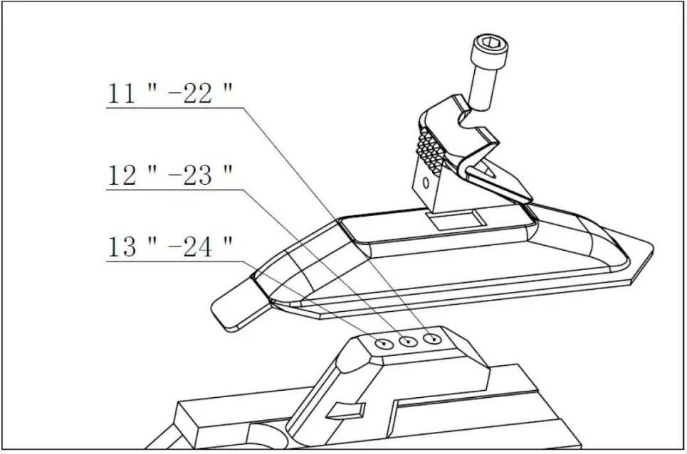
| Rim diameter(outward clamp) | Rim diameter(inward clamp) |
| 1st gear 11″~22″ 2 nd gear 12″~23″ 3 rd gear 13″~24″ | 1st gear 13″~24″ 2nd gear 14″~25″ 3rd gear 15″~26″ |
The default setting is at the second gear (12″~23″&14″~25″) when leaves factory. The operator can adjust the different gear according to the FIG1 showing in order to mount and demount kinds of rims.
1.5 ENVIRONMENT REQUIREMENT
ambient temperature 0℃~45℃ (32℉~113℉)
relative humidity 30~95%
Sea level max.1000M (304.8ft)
Without dust and flammable and explosive gas
The operation space around the machine wills not smallerthan the indicatedin FIG2![]() If the machine is installed outdoors, you must have the protective sheds to protect the rain and sun. It is forbidden to use in the site with the flammable gas!
If the machine is installed outdoors, you must have the protective sheds to protect the rain and sun. It is forbidden to use in the site with the flammable gas! 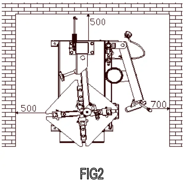
CHAPTER2 CONFIGERATION AND OPERATION
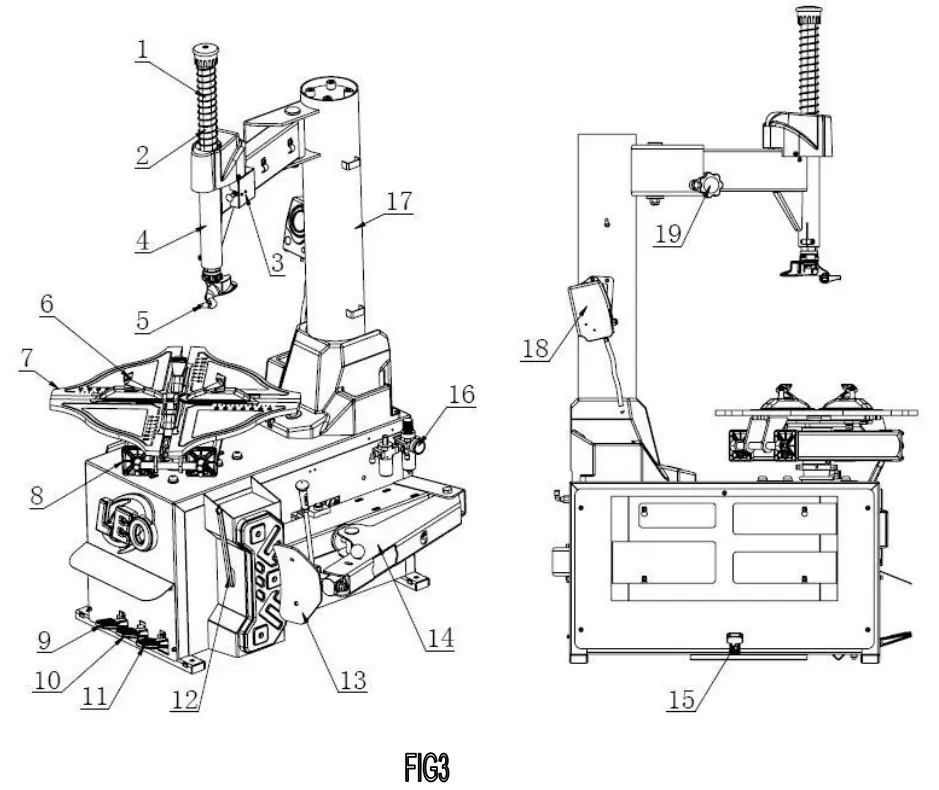
- vertical shaft spring 12—crowbar
- hexagon shaft13—bead breaking blade
- lock valve14—tire press arm
- swing arm15—quick inflation pedal (optional)
- demount head16—air regulator
- claw 17—column
- turntable18—inflation gauge
- clamp cylinder19—lock handle
- motor pedal
- clamp pedal
- tire press pedal
CHAPTER 3 INSTALLATION AND CALIBRATION
Before installation and debug, carefully read this manual. The unauthorized change on the parts and spare parts of the machine will cause the damage on the machine.
- Installation and debug personnel should have the specific electrical knowledge.
- Operators must be trained and authorized.
- Before installation, carefully read the equipment list. If any question, please contact with the dealers or our company.
- To ensure the success of the installation and debug, please prepare the following common tools:Two wrenches(10″), one socket wrenches, one set Allen Key, one pincer pliers, one screw driver, one hammer and one multi-purpose meter.
3.1UNPACK
3.1.1 According to the de-package instruction on the package box, to detach the box and remove the package material to check if the machine damage or not and if the spare parts completed.
3.1.2Keep the package material far away from the working site and deal with it properly.
3.2 INSTALLATION
3.2.1 After un-package the package carton, take out accessory boxes(FIG 4-2), and column assembly(FIG 4-1). And position the body according to the FIG2. Remove the bolt(FIG 4-3), elastic washer and plate washer on the body.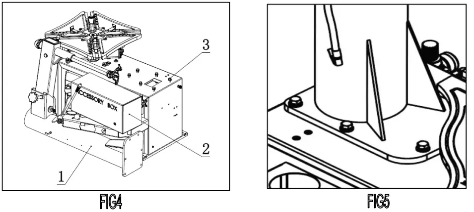
3.2.2 Place the column on the body. The direction of the warning label is forwards. Make the holes on the column base plate align to thread holes on the body. Once again assemble the removed the bolt(3.2.1), elastic washerand plate washer and plate washer removed in 3.2.1. The torque is 70 N·M(FIG5)Use torsion wrench to tight.
3.2.3Use the wrench to remove the screw(FIG 6-3)hexangular shaft(FIG6-1)and take off the vertical shaft cap( FIG 6-2).![]() When remove the screw on the vertical shaft cap, you need use the lock handle to lock the hexangular shaft to avoid sliding off to damage the machine or injury personnel!
When remove the screw on the vertical shaft cap, you need use the lock handle to lock the hexangular shaft to avoid sliding off to damage the machine or injury personnel!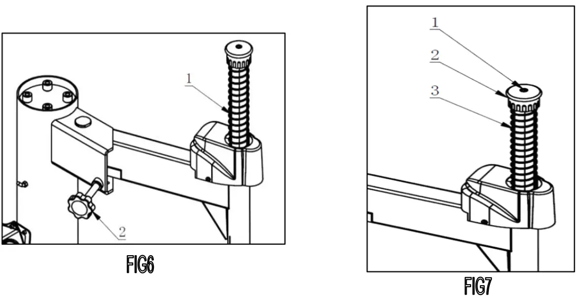
3.2.4Install the vertical shaft spring(FIG7-1)on the vertical shaft. Mount the vertical shaft cap and mount the removed screw and assemble the hand wheel into the nut bushing of the rocker arm(FIG 7-2).
3.2.5Take out the inflation gun then connect it the open nut and tighten it(FIG8). Hang the gun to the hook after installation.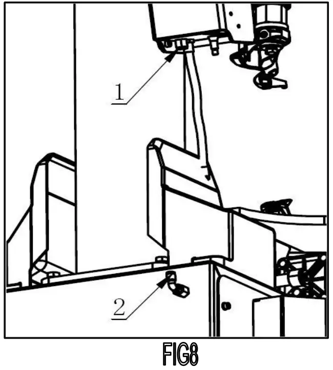 3.3 AIR SOURCE FITTING INSTALLATION:
Before the machine out of the factory, the air regulator has been adjusted well and can be re-adjust if need.
Adjust the pressure: lift-up the adjusting knob (FIG9-1) and rotate it clockwise, the pressure will raise. Otherwise, decline. (Adjust the working pressure of the machine and must not exceed 10Bar.)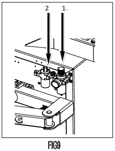 Adjust the oil feed: twist the adjusting screw (FIG9-2) clockwise using the screw driver to slow the dripping speed and otherwise, quicken it.
CHAPTER 4 DEMOUNT AND MOUNT TIRE
![]() Note: the operator must be trained and qualified then allow to operate the tire changer.Need to use the proper device and tools, wear the protective clothes, and use the proper safety precautions, like goggle, earplug, and safety shoe and so on.
Note: the operator must be trained and qualified then allow to operate the tire changer.Need to use the proper device and tools, wear the protective clothes, and use the proper safety precautions, like goggle, earplug, and safety shoe and so on.
4.1 BASIC PRINCIPLE
- In order to avoid damage the rim, especially the alloy rim, when mount and demount the ire, must use the specified crowbar.
- In order to facilitate the removal and protection the tire and rim, between the tire and rim, at the position which the bead break blade insert to, need to lubricate using industrial lubricants or soap water.
- For certain types of tires, pay attention to the tire wall and the rotation direction marked on the tire.
- The tire size must be suitable for the rim to mount.
- Before mount and demount the tire, need to check whether the rim had damage (deformation or surface of the outside of the rim, rim axial for radial beat is too big, corrosion or overall wear).
- In any case, pay attention to the mounting and demounting request of the special tire from the tire manufacturers.
When inflate the tire, to increase the pressure uniformly and pay attention to the tire edge situation.
4.2DEMOUNT TIRE
a) Deflate the air in the tire completely and pull out the core. Use the special tool to detach the weight on the rim.Place the tire between then bead breaking blade and tire pressing runner clog(FIG10).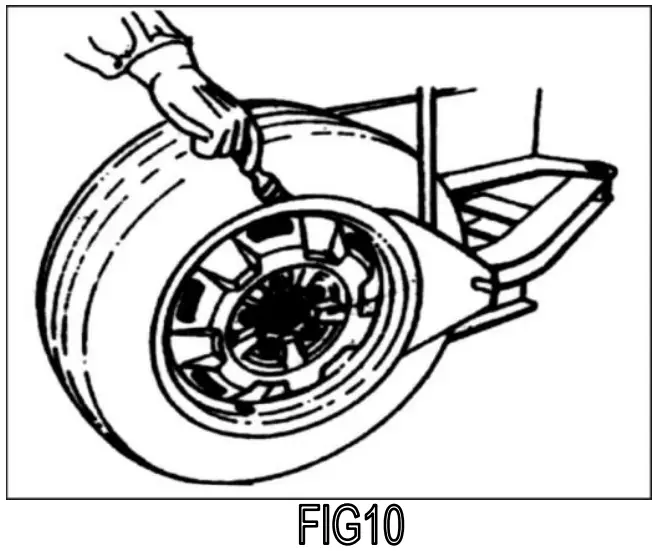 b) Place the tire between then bead breaking blade and tire pressing runner clog. Then step down the tire press pedal (FIG3-11) to detach the rim from the tire. Repeat the same operation on the other parts of the tire to make the tire completely detached from the rim. To detach the lip smoothly, you can use the brush to spread the lubricant or thick soap liquid between the lip and rim.
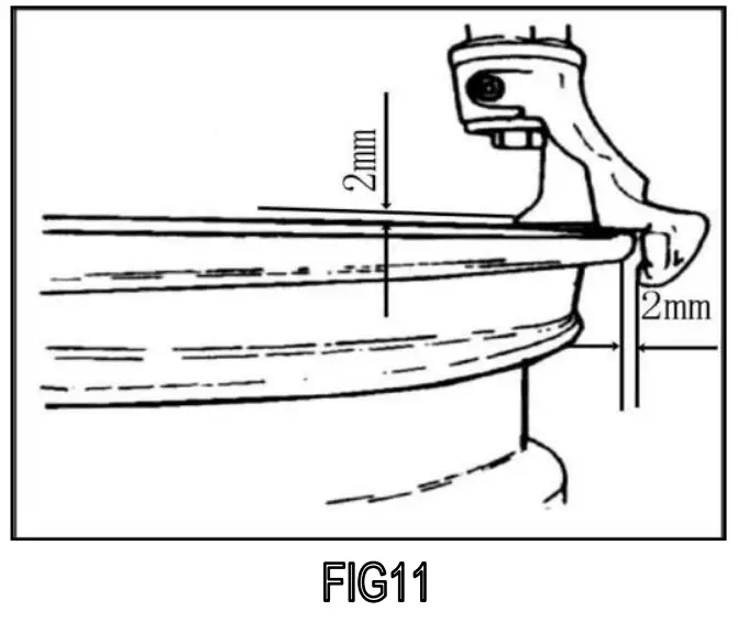 c) Place the wheel with the tire detached from the rim on the turntable and step the clamp pedal (fig3-10) to clamp the rim. You can select the outer clamp and inner clamp to clamp the wheel according to the different rim.
d) Position the hexangular shaft (FIG 3-3) to the working position to make the demount tool close to the rim of the wheel. And use the hand wheel (FIG 3-21) to push against the rocker arm and then use the lock handle (FIG3-20) to lock. The demount tool will automatically move a little of gap (FIG11).
NOTE: The angle of the demount tool has been calibrated according to the standard rim (14″). If handling the extra-big or extra-small rim, you can reposition.
e) Use the crowbar to detach until the lip to the hump of the demount tool. Step the turntable rotation pedal(FIG3-9)to rotate the turntable clockwise until the entire lip completely detached.
Note: If handling the tube tire, to avoid the damage on the tube, you should keep the nozzle of the tire 10cm from the right side of the demount tool when demounting. If the demount of the tire is jammed, please stop the machine immediately and then lift up the pedal to let the turntable rotate counterclockwise to remove the resistance!
f) When handling the tube tire, Take out the tube and then move the lower lip upwards to the upper edge of the rim and then repeat the above steps to detach the other lip.
4.3 MOUNT TIRE: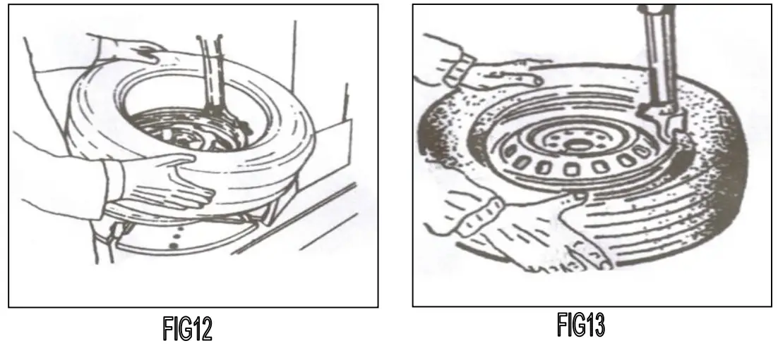 a) Clean the dirt and rust on the rim and lock it on the chuck.Lock the rim on the turntable.
b) Spread the lubrication liquid or soap liquid around the lip. Tilt the tire against the rim and keep the front end upwards. Press down the hexangular shaft to move the demount arm to contact with the rim and lock. The left lip above the tail of the demount tool and the right lip will be positioned under the front end of the demount tool (FIG 1), Clockwise rotate the turntable to guide the bottom lip into the tire detaching slot.
c) If there is tube, place it in the tire and plug the core. And assemble the lip according to the above mentioned step (FIG13). In the process of clamping the rim, do not reach your hands in between the rim and the claw to avoid the damage to the personnel.
4.4 INFLATION:
NOTE: When inflating the tire, please be carefully and series obey the operation process. Check the air route to see if the air connection is OK. This machine is equipped with an inflation gauge for monitoring the inflation of the tire and the inflation pressure.
4.4.1 Regular inflation
NOTE: When inflating the tire, please be carefully and series obey the operation process. Check the air route to see if the air connection is OK. This machine is equipped with an inflation device for monitoring the inflation of the tire and the inflation pressure.
a) Loose the tire from the turntable.
b) Connect the inflation hose with the tire air core.
c) In the process of inflation, you should repeat stepping the inflation pedal. Confirm the pressure indicated on the pressure gauge not exceed the scope specified by the manufacturer. In this machine, there is a pressure decrease valve to keep theinflation pressure not exceed 3.5bar.
d) For tubeless wheel with lax tire, the common inflation is invalid and can use the quick inflation then common inflation. (The quick inflation function is not standard configuration and need to special order).
e) Step down the inflation pedalto the bottom position (second gear) and quickly release the pedal when the tireis full to the position of the first gear.
Note: the machine equips the reducing valve and set the pressure value at 3.5 bar. Customers can get different inflation pressure by adjusting the pressure decrease valve according to their own requirement.If the inflation pressure too high, you can press down the deflation press button on the inflation device to reach the required air pressure.
Warning! Explosive!
When inflation, you must follow the above safety operation and abide by the following instruction:
- Carefully check is the size of the rim same to the size of the tire and also check the wear condition of the tire to secure there is no damage before inflation.
- When the inflation pressure is relatively high, you should remove the tire from the machine and inflate in the protective cover.
- When inflate the tire, be carefully, keep your hands and body far away from the tire.
Chapter 5MAINTANENCE & REPAIR
![]() NOTE: Only the qualified professional personnel can execute the maintenance.
NOTE: Only the qualified professional personnel can execute the maintenance.
Before any maintenance, Cut off the power.And ensures the maintenance personnel can take charge of the power plug. Meanwhile, cut off the air supply and push the air supply switch to the off position and completely deflate the residual air in the machine.
The following position should be monthly maintenance:
- Keep the machine and working area clean.
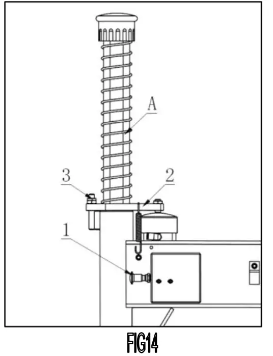
- Use the diesel oil to clean the hexangular shaft (FIG14), Use the machine oil to lubricate.
- Use the diesel oil to clean the turntable claw and its guide and use the lithium base oil to lubricate.
- Periodically check the lubrication oil level in the oil fog device. If the oil level lower than the oil scale, please feed in the SAE30 lubrication oil in time.Periodically drain out the water and impurity in the oil water separator.
- Periodically check and adjust the tension of the driven belt. Properly adjust the adjust nut in Aand B to realize the proper tension.
- Check all the connect parts and tight the loosen bolt.
HEXANGULAR SHAFT & LOCK PLATE LOCK GAP ADJUSTMENT
When press downward the hexangular lock handle (FIG14-1), the hexangular shaft will vertically slide under the effect of the weight of the hexangular shaft and return spring; When the lock handle rotate clockwise for about 100 degree, the cam connected to the handle will push up the lock plate to lock the hexangular shaft. Meanwhile, the demounting head will slide upward 2mm to have a gap between the demounting head and rim. If you cannot realize this situation, you can adjust the locking nut (FIG14-3) at front end of locking plate (FIG14-2) to reach the target. Adjust upward, big gap; adjust downward, small gap.
CHAPTERVI TRANSPORTATION
When transport the machine must apply the original package and place according to the mark on the package. The machine must be transported by the forklift with the corresponding tonnage(FIG15)and the stacked layer will not exceed 3layers.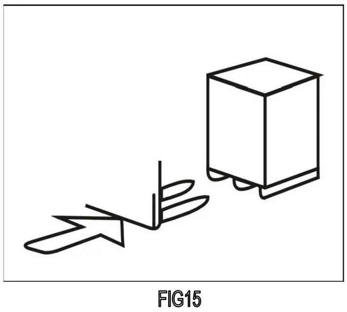
CHAPTER ⅦELECTCTRICAL AND PENUMATIC DRAWING
7.1. 220V ELECTRICAL PRINCIPLE DRAWING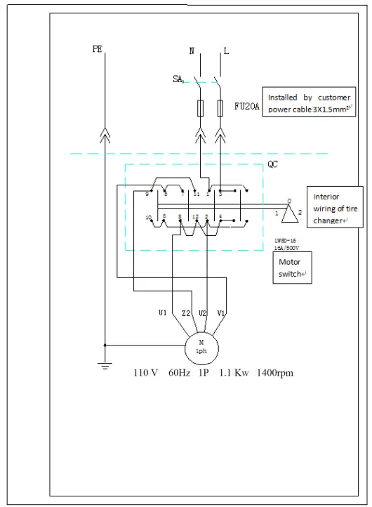
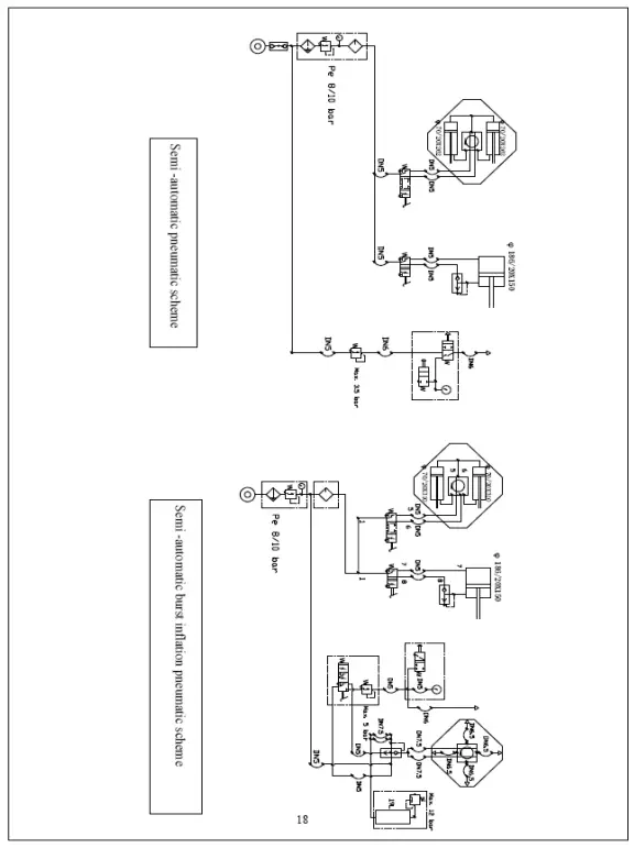
7.4. PNEUMATIC PRINCIPLE DRAWING
CHAPTER Ⅷ TROUBLESHOOTING ANALYZE AND SOLUTION
| CHAPTER | REASON | TROUBLESHOOTING |
| Turntable rotates in one direction. | Universal switch contact burned | Change Universal switch |
| Turntable does not rotate. | Belt damage Belt too loose Motor or power source have problems Universal switch contact damage | Change belt Adjust the tension of the belt Check motor, power source and power source cable Change motor if motor burned Change Universal switch |
| Turntable cannot clamp the rim as normal | Claw worn Clamp cylinder air leakage | Change claws Change the air leakage sealing parts |
| Quadric and hexangular shaft cannot lock | Lock plate not in position | Refer to the chapter V |
| Chassis pedal not return. | Pedal return spring damage | Chang torsion spring |
| Motor not rotate or the output torque not enough | Drive system jam Capacitor broken down Voltage not enough Short-circuit | Remove the jam Change capacitor Wait for the restore of the voltage Remove |
| Cylinder output force not enough | Air leakage Mechanic fault Air pressure not enough | Change sealing parts Remove the fault Adjust the air pressure to meet the requirement |
| Air Leakage | air hose broken pipe fitting broken sealing head broken loss of the sealing glue | Change broken parts Refill the sealing glue |
CHAPTER 9 EXPLODED VIEW OF MACHINE
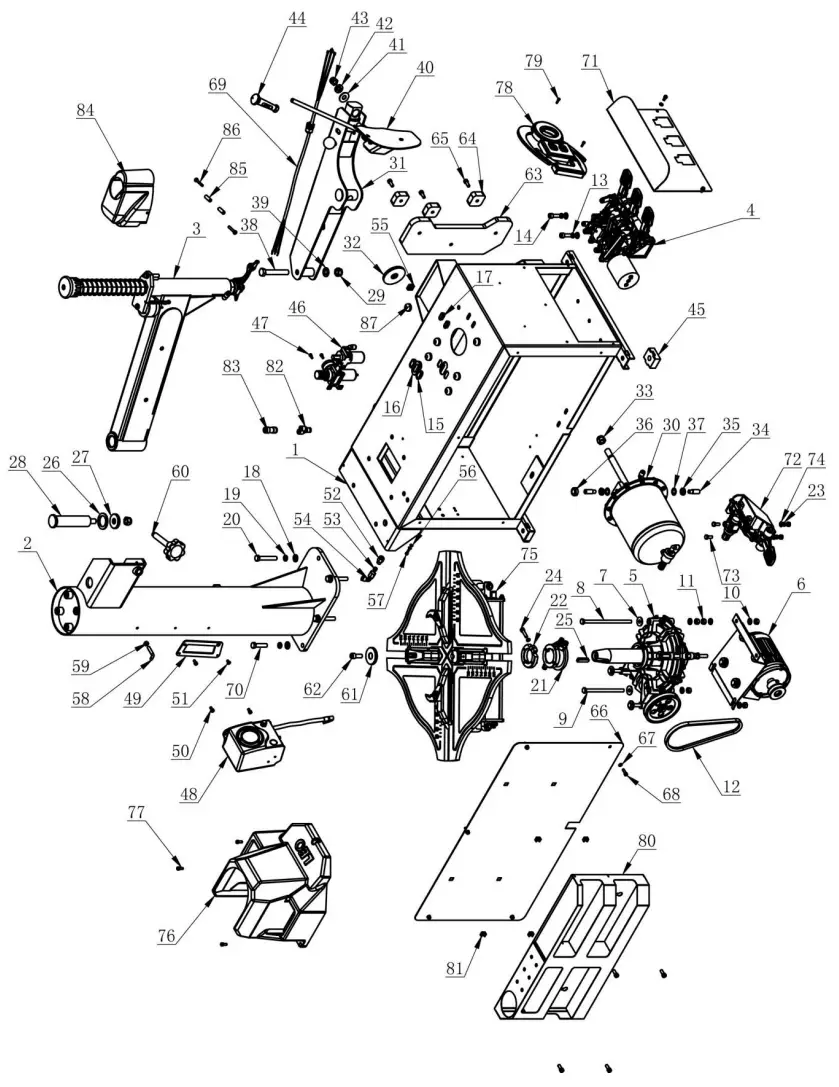
| ITEM | PART. NO | DESCRIPTION. | QT. Y |
| I | C-1.2-1100000 | BODY | 1 |
| 2 | C-L I- I 2CO300 | 031.1011 | 1 |
| 3 | C-L2-1300000A | SWING ARM | 1 |
| 4 | CT-D-9100000 | PEDAL ASSEMBLY | 1 |
| 5 | CT-J-4100000 | GEARBOX ASSEMBLY | 1 |
| 6 | CT-DJ-0334122 | MOTOR (380V. 5011z. 3P. 0.75K•) | 1 |
| 7 | GB96.1-10 | LARGE WASHER A GRADE | 6 |
| 8 | 665781-MI0X200 | BOLT MIO X 200 | 4 |
| 9 | GB5781-M10 X 160 | BOLT MIO X 160 | 2 |
| 10 | 6895-10 | FLAT WASHER | 16 |
| 11 | 6641-1410 | HEXANUULAR NUT | 14 |
| 12 | CT-DJ-0300007 | BELT | 1 |
| 13 | GB93-10 | STANDARD SPRING WASHER | 2 |
| 14 | GB70.1-1410 X 30 | INNER HEXA CYLINDRICAL SCREW | 2 |
| 15 | C-54-1000022 | PUJG C | 2 |
| 16 | C-54-1000028 | PLUG B | I |
| 17 | C-54-1000023 | PLUG A | 2 |
| 18 | 6895-12 | FLAT WASHER | 6 |
| 19 | GB93-12 | STANDARD SPRING WASHER | 6 |
| 20 | GB5782-512 X 75 | HEXANGULAR BOLT | 4 |
| 21 | CT-Q-5003000 | ROTATING UNION | I |
| 22 | CT-Q-6000000 | CLAMP RING | I |
| 23 | G893-8 | STAMIARD SPRING WASHER | 3 |
| 24 | 0370.1-M8 X 30 | INNER LIBRA CYLINDRICAL SCREW | I |
| 25 | 681096-C12X 8 X 45 | LUMMON FLAT KEY | 1 |
| 26 | C-54-1000011 | ADJUSTING WASHER | 1 |
| 27 | C-54-1000009 | SHAFT WASHER | I |
| 28 | C-54-1000008 | VERTICAL SHAFT | 1 |
| 29 | 60889. 1 -MI6 | I-TYPE PREVAILING TORQUE TYPE HEXAGON LOCK ram | 2 |
| 30 | CT-LS-9200000 | BEAD BREAKER CYLINDER ASSBIBLY | 1 |
| 31 | CT-B-0000000 | BEAD BREAKER | 1 |
| 32 | C-54-1000016 | RUBBER WASHER | I |
| 33 | 0889.2-MI8X I.5 | NUT M18X1.5 | I |
| 34 | C-54-1000010 | SCREWS M14X42 | 2 |
| 35 | GB6172.14114 | HEXANGUAR THIN NUT | 2 |
| 36 | C-54-1000013 | SEALED COVER | I |
| 37 | 68861. 1-14 | INNER TO0111 LOCK WMISER | 2 |
| 38 | 6B5780-MI6 X 100 | HEXANGUIAR B017 | I |
| 39 | GB95-16 | FLAT WASHER | I |
| 40 | CT-C-2200000 | BEAD BREAKER BLADE | I |
| 41 | 6-54-1000002 | WASHER | I |
| 42 | GB955-14 | WAVE-FORM SPRING WASHER | I |
| 43 | GB889.1 -MI4 | I-TYPE PREVAILING TORQUE TYPE HEXAGON LOCK NUT | 1 |
| 44 | C-LI -1300001 | RUBBER COVER | 1 |
| 45 | C-54-1000005 | RUBBER FOOT | 4 |
| 46 | CT-F-3121100 | AIR REGULATOR ASSEMBLY | 1 |
| 47 | GB70.1115)(12 | INNER HEXA CYLINDRICAL SCREW | 2 |
| 48 | CT-K-3100000 | INFLATOR COVER ASSEMBLY | I |
| 49 | C-54-1000035 | JONCTINN PLATE | 1 |
| 50 | GB70.1-116)(12 | INNER HEXA CYLINDRICAL SCREW | 8 |
| 51 | GB70.3-110(12 | INNER COUNTERSUNK SCREW | 1 |
| 52 | FPC 8-02 | MALE STRAIGHT | 1 |
| 53 | C-54-1000027 | JOINT SEALING GASKET | 1 |
| 54 | FPLF 8-02 | FEMALE ELBOW | 1 |
| 55 | C-54-1000015 | STOP-UP | 1 |
| 56 | GB95-5 | FLAT WASHER | 2 |
| 57 | GB5782-M5>(16-8.8 | HEXANGULAR BOLT | 1 |
| 58 | C-71-1000024 | INFLATING GUN HOOK | 1 |
| 59 | GB41 -M8 | HEXANGULAR NUT | 3 |
| 60 | C-LI -1400000 | HANDLE WHEEL | 1 |
| 61 | C-54-1000012 | PRESS COVER | 1 |
| 62 | 61370.1 -M12)(30 | INNER HEXA CYLINDRICAL SCREW | 1 |
| 63 | C-LI -1000002 | !ESHER | 1 |
| 64 | C-LI -1000003 | WASHER | 3 |
| 65 | GB70.1 -M8)<20 | INNER HEXA CYLINDRICAL SCREW | 7 |
| 66 | C-LI -1000004 | SIDE PLANEL | 1 |
| 67 | GB95-6 | FLAT WASHER | 10 |
| 68 | GB70.1 -M6)<20 | INNER HEXA CYLINDRICAL SCREW | 5 |
| 69 | CT -E-UN00410 | CABLE (3P) | I |
| 70 | GB5782 -M12><50 | HEXANGULAR BOLT | 2 |
| 71 | C-LI -1000005 | PROTECTIVE COVER | 1 |
| 72 | CT-K-1E00000 | QUICK INFLATION PEDAL ASSY | I |
| 73 | GB5781 -M8X20 | HEXANGULAR BOLT | 2 |
| 74 | GB95-8 | FLAT WASHER | 2 |
| 75 | CT-Y-5E00000 | TURNTABLE ASSEMBLY | 1 |
| 76 | C-LI -1000001 | TOOL BOX | I |
| 77 | GB70. 1 -M6>(16 | INNER HEXA CYLINDRICAL SCREW | 3 |
| 78 | C-LI -1000100 | LOGO | 1 |
| 79 | GB70.1 -M4>(I6 | INNER HEXA CYLINDRICAL SCREW | 2 |
| 80 | C -LI -1000200A | TOOL BOX | 1 |
| 81 | 8-76-1400004 | CLIP NUT | 4 |
| 82 | FPY-8 | Y-SILU’E INSERT FITTINGS8 | 1 |
| 83 | FPG 8-6 | FEMALE ELBOW | 1 |
| 84 | C-4H -1000001 | PROTECTION COVER | 1 |
| 85 | C-77-1000006 | PROTECTIVE HOOD LOCK BUSHING | 2 |


