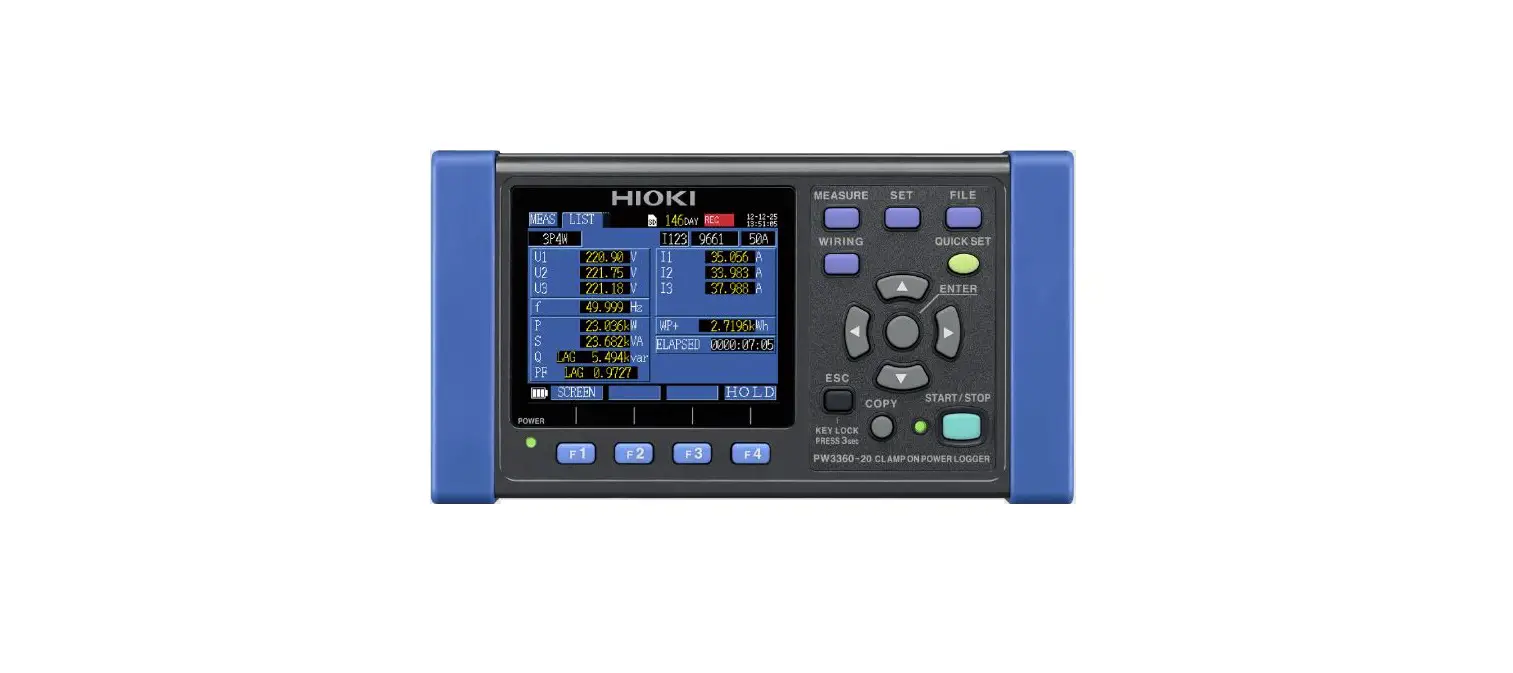
HIOKI PW3360 Clamp-on Power Logger
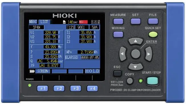
Reliable measurements start with proper wiring
- See demand and trend graphs on siteSee demand and trend graphs on site
- Supports single to three-phase, 4-wire circuitsSupports single to three-phase, 4-wire circuits
- Simultaneously measure up to three single-phase, 2- wire circuits (in the same power system).
- Measure up to 780V with a 1000V display range
- Broadly applicable for many jobs, including leakage current measurement
- An optional clamp-on leakage sensor supports measurements as low as 50 mA.
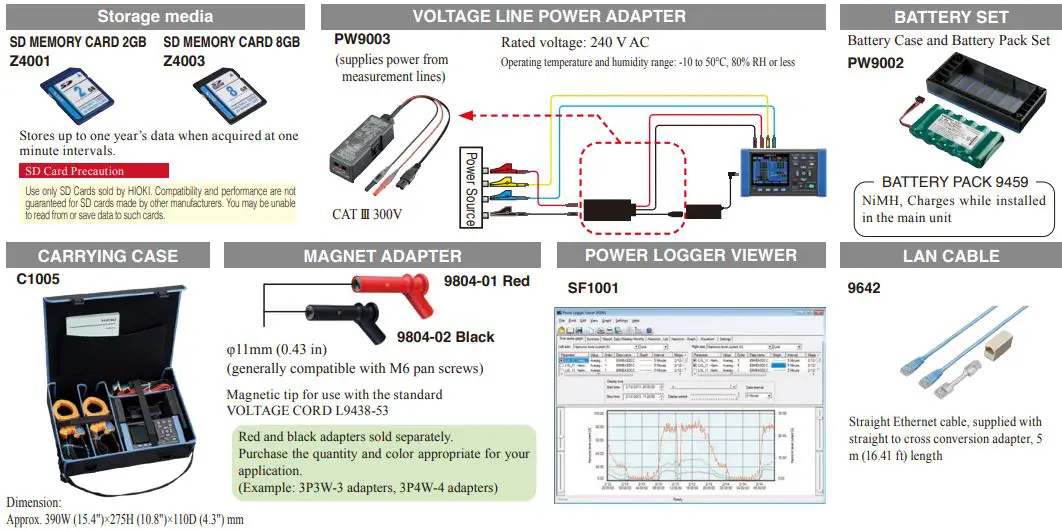
- Store months of data on SD cards
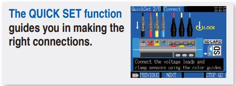
Begin with QUICK SET Convenience
Select your Wiring Type, Clamp and Destination, and Connect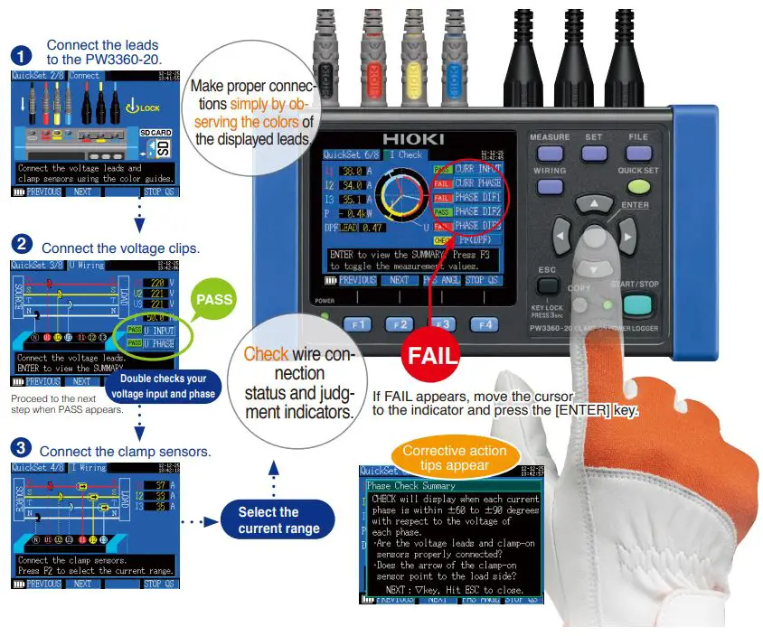
Miswiring Example (Clamp Orientation)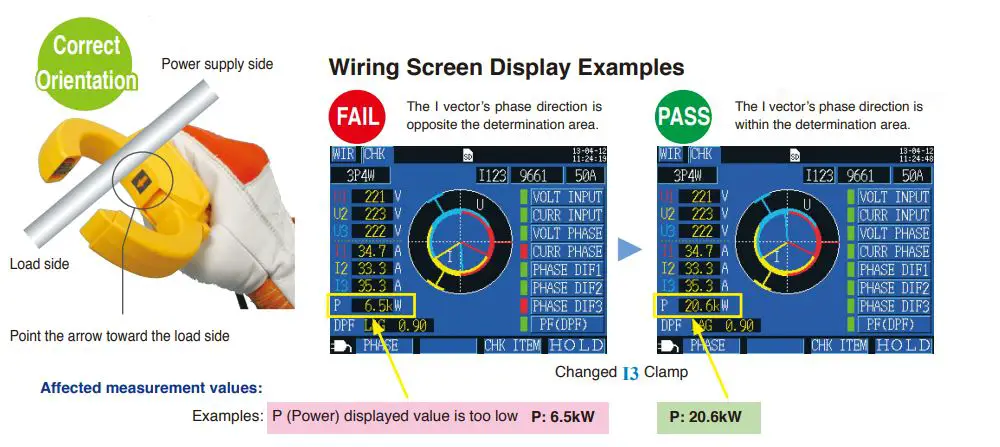
Graph Display
Reveal Power Consumption State! Graph Display Functions
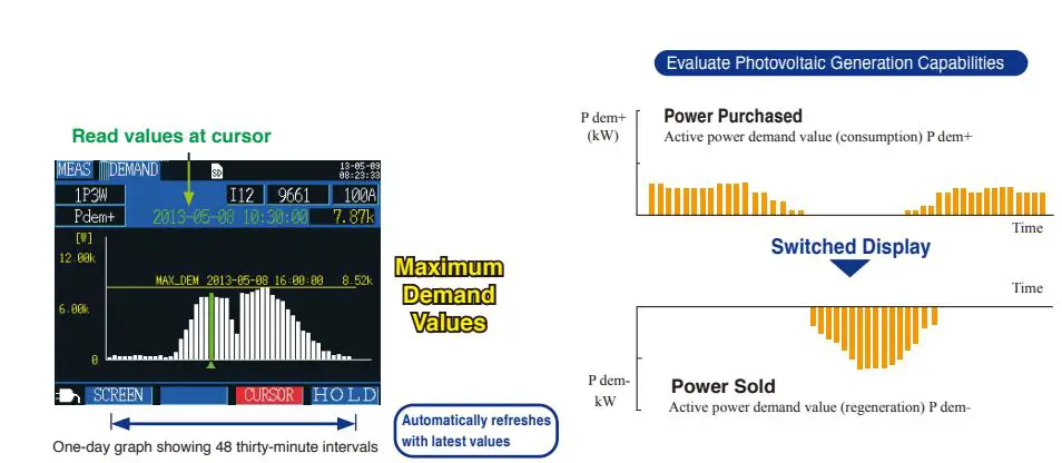
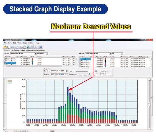
- Demand Graph Display
Shows the demand value transitions useful for managing pow-er consumption. Check maximum demand values and times while recording.
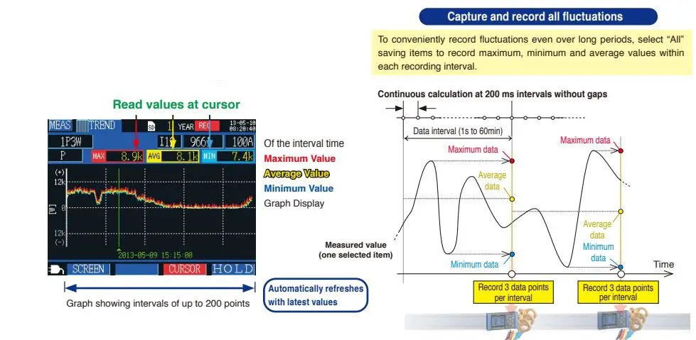
- Trend Graph Display
From all measurement items, select one for display. Check states such as power fluctuations of devices in on-site operating conditions.
Create a Graph to Clearly Grasp Power Consumption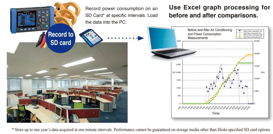
Accommodates All Worksites
Tight spaces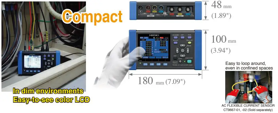
Where no AC power is available
Battery* power provides about eight hours of continuous opera-tion. In addition, a Voltage Line Power Adapter* is available to power the PW3360-20 from the measurement lines.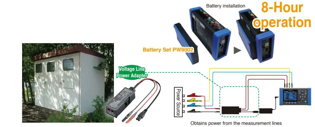
In severe temperature environments
The operating temperature range extends from –10°C (14°F) to 50°C (122°F). Even under battery operation, measurements can be performed from 0 °C (32°F) to 40°C (104°F) (0°C (32°F) to 50°C (122 °F) when using LAN communication).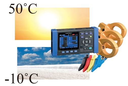
Magnetic voltage adapters for hard-to-clip terminals
Magnetic voltage adapters convertible with the Voltage Cords L9438-53 let you accurately detect voltage when the circuit terminals are too shallow for alligator clips to latch on. * Magnetic Adapter 9804 option sold separately. 9804-01 Magnetic Adapter (red) usage example.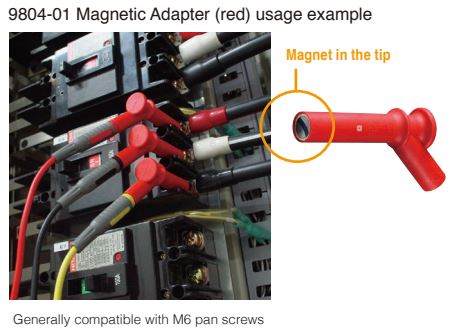
Loaded with More Useful Functions
Simultaneous Measurements
Simultaneously measures three single-phase 2-wire circuits in the same system.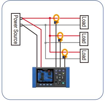
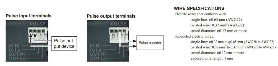
Pulse Input
The pulse input function can be used to record power data and production volume counts simultaneously. The power data and pulse volume (production volume) information are useful for unit cost production management.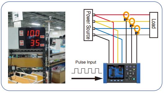
Pulse Output
Use the Pulse Output function to acquire temperature and pulse (electrical energy) data simultaneously with a data logger. Evaluate the relationship between air conditioner temperature control settings and power consumption.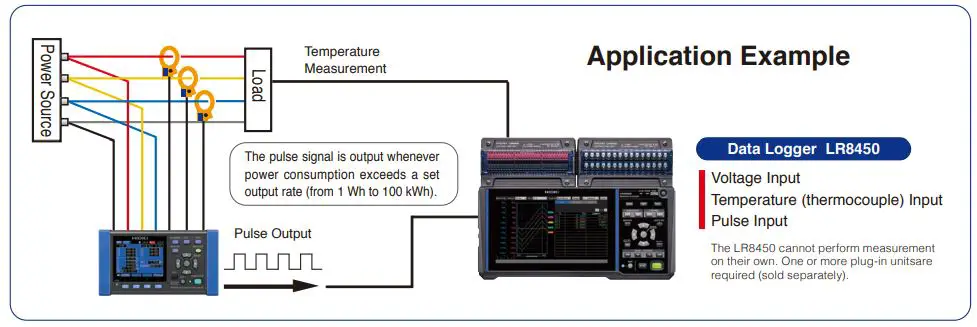
Leakage Current Measurement
With the optional leakage current clamp on sensors, turn the instrument into a 3-channel leakage current logger to help identify trouble spots.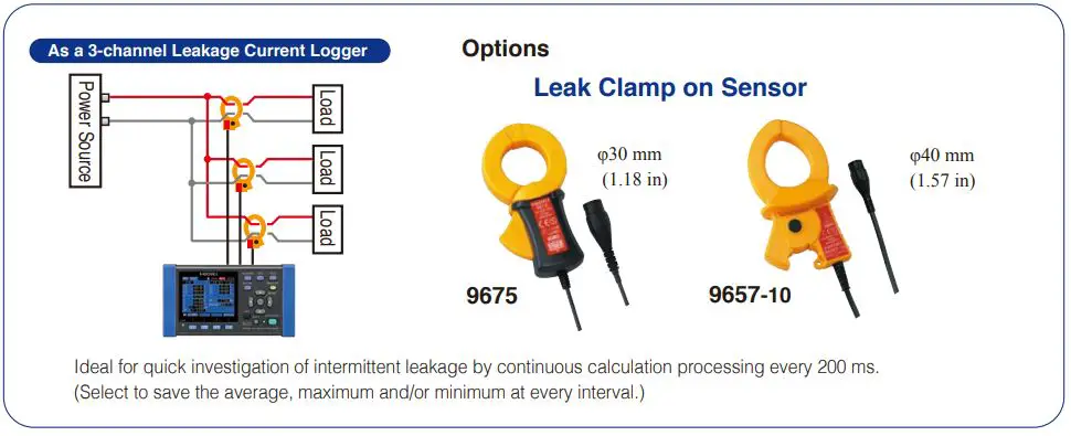
Harmonic Measurement Model
PW3360-21
Analyze voltage and current harmonics on a 50/60 Hz power line from the fundamental waveform to the 40th order.
- Displays the RMS value, content, and phase angle (numerical list or graph display) for each harmonic order.
- Vector display of power phase angle
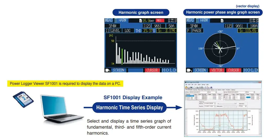
Maximum, average, and minimum values can be saved in binary format to SD card at each interval.
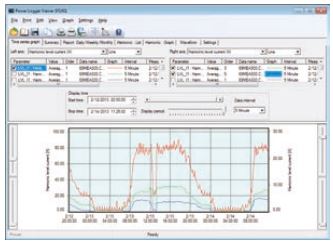
Power Logger Viewer SF1001 (option, sold separately)
Data saved to an SD card or internal memory can be loaded into a PC for expanded display, aggregation and analysis.
Supported models: PW3360, PW3365, 3169-20
On the same time axis, view measured power consumption and equipment operating status at specific intervals, along with equipment characteristics and management details.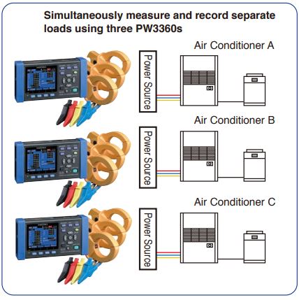
- Trend graph display function
- Summary display function
- Waveform display
- Harmonic display
- Copy function
- Print function
- Report printing
Stacked Graph Display Example
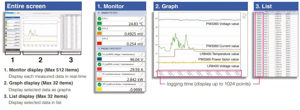
Get results from the job site in real-time
Present data from multiple sources as a graph or list together in real-time: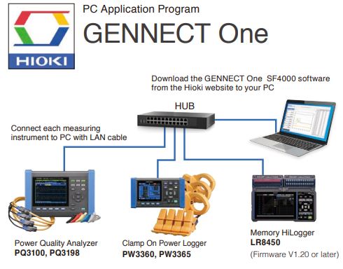
Simultaneously monitor all data in real-time
- Connect measuring instruments to PC with LAN cable Operation guaranteed for up to 30 units. Please contact your nearest Hioki distributor for connections exceeding 30.
- Software automatically recognizes LAN-connected measuring instrument
- Display acquired data as graphs in real-time The measured value (present value) displayed by the measuring instrument is obtained at a certain interval (minimum 1s interval) according to the timer on the PC.
- Operate measuring instruments connected via LAN from a PC
- Automatically transfer files saved on a LAN-connected measuring instrument to a PC
- Manage and save results with software
- List MAX, MIN and AVG values (Display time of MAX & MIN data)
LAN remote control function
The application displays a virtual instrument, allowing you to control it directly with the mouse. You can also easily change instrument settings and control the instrument, for example to start and stop measurement.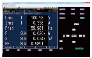
LAN automatic file download function
This function lets you acquire data in real time on a PC, including data created when the instrument’s trigger is activated and measurement files that are automatically generated on a daily basis. Example uses include capturing abnormal phenomena with an instrument installed in the field and automatically acquiring daily power consumption data on a PC.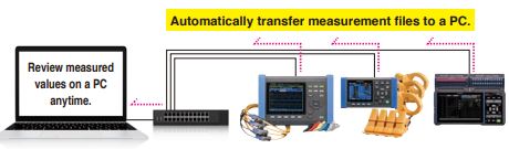
Downloading GENNECT One SF4000

| Compatible instruments | Available items to monitor and save on PC | Number of items that can be saved | Recording time | |
| POWER QUALITY ANALYZER PQ3100, PQ3198 | Voltage Current Power | Instantaneous value of each interval; MAX, MIN, AVG value of each interval | Save up to 512 items *Maximum 32 items when simultaneously displaying graphs | When memory size of acquired data reaches to 64MB, data will be separated automatically [Continuous measurement] When storage capacity falls below 512MB, measurement will stop |
| CLAMP ON POWER LOGGER PW3360, PW3365 | ||||
| POWER ANALYZER PW3390, PW6001 | Instantaneous value of each interval | |||
| MEMORY HiLOGGER LR8450, LR8450-01 | Temperature Analog Input | |||
| WIRELESS LOGGING STATION LR8410 | ||||
| MEMORY HiCORDER MR6000 | ||||
Specifications
PW3360-20, PW3360-21
Input specifications
| Measurement line type | Single-phase 2-wire, single-phase 3-wire, three-phase 3-wire, three-phase 4-wire |
| Measurement line Frequency | 50/ 60 Hz |
| Number of input channels | Voltage: 3 channels U1 to U3 Current: 3 channels I1 to I3 |
| Voltage range | 600 V AC |
| Total display area: 5V to 1000 V (less than 5 V displays as 0 V) When RMS voltage is zero, zero is displayed for all orders of harmonic voltage. | |
| Effective measurement range: 90 V to 780 V, peak: ±1400V | |
| [OVER] indicates over-range warning | |
| Current ranges | Load current |
| CLAMP ON SENSOR 9694 : 500 m/1/5/10/50 A | |
| CLAMP ON SENSOR 9695-02 : 500 m/1/5/10/50 A | |
| CLAMP ON SENSOR 9660 : 5/10/50/100 A | |
| CLAMP ON SENSOR 9695-03 : 5/10/50/100 A | |
| CLAMP ON SENSOR 9661 : 5/10/50/100/500 A | |
| CLAMP ON SENSOR 9669 : 100/200/1 k A | |
| AC FLEXIBLE CURRENT SENSOR CT9667-01 : 50/100 /500/1 k/5 kA | |
| AC FLEXIBLE CURRENT SENSOR CT9667-02 : 50/100 /500/1 k/5 kA | |
| AC FLEXIBLE CURRENT SENSOR CT9667-03 : 50/100 /500/1 k/5 kA | |
| Leakage current | |
| LEAK CLAMP ON SENSOR 9657-10 : 50 m/100 m/500 m/1/5 A | |
| LEAK CLAMP ON SENSOR 9675 : 50 m/100 m/500 m/1/5 A | |
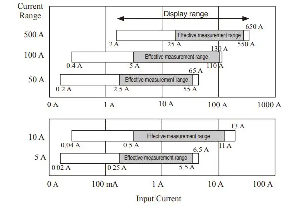
| Total display range: Within 0.4 to 130% of the range | |
| (zero is suppressed for less than 0.4%) | |
| When RMS current is zero, zero is displayed for all orders of | |
| harmonic current. | |
| Effective measurement range: Within 5 to 110% of the range peak: ±400% of range, however, maximum range is 200%. | |
| [OVER] indicates over-range warning | |
| Power ranges | 300.00 W to 9.0000 MW Depends on voltage/current combination and measured line type (see Measurement Range Configuration Tables) |
| Total display range: Within 0 to 130% of the range (“0W” display indicates zero rms voltage and/or current) When RMS voltage and current are zero, zero is displayed for all orders of harmonic active power and harmonic reactive power. | |
| Effective measurement area: Within 5 to 110% of the range | |
| VT ratio settings | Any (0.01 to 9999.99) Selections (1/60/100/200/300/600/700/1000/2000/2500/5000) |
| CT ratio settings | Any (0.01 to 9999.99) Selections (1/40/60/80/120/160/200/240/300/400/600/800/1200) |
| Input methods | Voltage: Insolated inputs (except between U1, U2, U3 and N) Current: Isolated input using a clamp-on sensor |
| Input resistance | Voltage input part: 3 MΩ ±20% (50/ 60 Hz) |
| Maximum rated voltage between terminals | Voltage input section: 1000 VAC, 1400 Vpeak Current input section: 1.7 VAC, 2.4 Vpeak |
| Maximum rated voltage to earth | Voltage input section: 600V Measurement Category III 300V Measurement Category IV Current input section: Depends on clamp sensor in use. |
Pulse input
| Input specifications | No-voltage contact input (counts when shorted terminals open) Voltage input (Hi: 2 V to 45 V, Lo: 0 V to 0.5 V, counts at Lo to Hi) Maximum rated input between terminals: 45 V DC Maximum rated input to ground: not isolated (GND is equipment com- mon) |
| Measurement range | 0 to 9999 (maximum pulse count per save interval) |
| Filter | Filter On (for mechanical contacts) 25 Hz or less, and at least 20 ms Hi and Lo pulse width |
| Filter Off (for solid-state contacts) 5 kHz or less, and at least 100 µs Hi and Lo pulse width | |
| Scaling | Displays product of pulse count and scaling factor setting Setting ranges: 0.001 to 1.000, and 1.000 to 100.00 |
Measurement items
| Voltage | RMS value, fundamental wave value,waveform peak (absolute value), fundamental wave phase angle, frequency (1) |
| Current | RMS value, fundamental wave value,waveform peak (absolute value), fundamental wave phase angle |
| Power | Active power, reactive power (with lag/lead display), apparent power, power factor, (with lag/lead display) or displacement power factor (with lag/lead display), active energy (consumption, regeneration, regeneration), reactive energy(lag, lead) Energy cost display (per-kWh price × power consumption) |
| Demand | Active power demand value (consumption, regeneration), reactive power demand value (lag, lead), active power demand quantity *(consumption, regeneration), reactive power demand quantity *(lag, lead), power factor demand value, pulse input * Only data output to SD card |
| Harmonic | Harmonic voltage, current, power level, content , phase angle Total harmonic distortion factor (THD-F or THD-R) |
Measurement screen
| List | Voltage RMS value, current RMS value, frequency, total active power, total reactive power, apparent power, power factor or displacement power factor, active energy (consumption), elapsed time |
| U/I | Voltage RMS value, voltage fundamental wave value,voltage waveform peak, voltage fundamental wave phase angle, current RMS value, current fundamental wave value, current wave- form peak, current fundamental wave phase angle |
| Power | Per-channel and total active power, apparent power, reactive power,power factor or displacement power factor |
| Integ | Active energy (consumption, regeneration), reactiv energy (lag,lead), recording start time, recording stop time, elapsed time, energy cost |
| Demand | Active power demand value (consumption, regeneration), reac- tive power demand value (lag, lead), power factor demand value, or pulse input Displays the maximum active power demand value and the time at which it occurred (this information is not saved). (data from up to 48 intervals is internally stored, then refreshed oldest-first). |
| Harmonic | Graph (voltage, current and power levels, content percentage and phase angle) List (voltage, current and power levels, content percentage and phase angle) |
| Waveform | Displays voltage and current waveform, voltage and current RMS values, and frequency. With a 3P3W3M connection, displays the phase voltage wave- form from the virtual neutral point. |
| Zoom | Enlarged view of 4 user-selected parameters |
| Trend | For one selected measurement item (except demand and harmon- ics), displays maximum, average and minimum values, with cursor calculations available (Note: with Trend display, there is no power- off backup function). |
External interfaces Specifications
| SD card Interface | Settings data, measurement data, screen data, waveform data |
| LAN interface | 100BASE-TX IEEE802.3 Compliance – HTTP server function – FTP server function |
| USB interface | USB Ver 2.0, Windows 10 (32/64bit)/ Windows 8 (32/64bit)/ Windows 7 (32/64bit) / Vista (32bit) /XP – When connected to a computer, the SD Card and internal memory are recognized as removable storage devices. |
Pulse output
| Function | Output pulse rate is proportional to active power consumption (WP+) when measuring integral power consumption |
| Pulse rate | OFF/ 1 Wh/ 10 Wh/ 100 Wh/ 1 kWh/ 10 kWh/ 100 kWh/ 1000 kWh (Default: 1 kWh) |
| Pulse width | approx. 100 ms |
| Output signal | Open-collector 30 V, 5 mA max (photocoupler isolated) Active Low |
General Specifications
| Display device | 3.5 inch TFT color LCD (320 × 240 pixel) |
| Japanese, English, Chinese, Korean, German, Italian, French, Spanish, Turkish Backlight auto-off function (after 2 minutes) When AUTO OFF is active, the Power LED blinks | |
| Operating environment | Indoors, Pollution degree 2, altitude up to 2000 m (6562-ft.) |
| Operating temperature and humidity (no condensation) | -10°C to 50°C (14°F to 122°F), 80% RH or less During LAN communication: 0°C to 50°C (32°F to 122°F), 80% RH or less During battery operation: 0°C to 40°C (32°F to 104°F), 80% RH or less During battery charging: 10°C to 40°C (50°F to 104°F), 80% RH or less |
| Storage temperature and humidity (no condensation) | -20°C to 60°C (-4°F to 140°F), 80% RH or less However, the batteryُs storage temperature range is -20°C to 30°C (-4°F to 86°F), 80% RH or less |
| Dielectric strength | 4.29 kVrms AC (1 mA sense current) between voltage input ter- minals and external terminals, 50/ 60 Hz for 60 sec. |
| Applicable standards | Safety: EN61010, EMC: EN61326, EN61000-3-2, EN61000-3-3 |
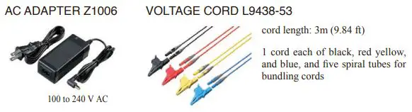
| Power supply | •Z1006 AC Adapter (12 V, 1.25 A), Rated supply voltage 100 VAC to 240 VAC, Rated power supply frequency 50/60 Hz •Model 9459 Battery Pack (Ni-MH DC7.2 V 2700 mAh) |
| Charge function | Charges the battery regardless of whether the instrument is on or off. Charge time: Max. 6 hr. 10 min. (reference value at 23°C) |
| Maximum rated power | • When the Z1006 AC Adapter is used: 40 VA (including AC adapter), 13 VA (PW3360-20 instrument only) •When the 9459 Battery Pack is used: 3 VA |
| Continuous battery operation time | Approx. 8 hr. (Continuous, backlight off) (when using the battery pack) |
| Backup battery life | Clock and settings (Lithium battery), Approx. 10 years @23°C (@73.4°F) |
| Dimensions | Approx. 180W(7.09″) × 100H(3.94″) × 48D (1.89″) mm (without PW9002) Approx. 180W(7.09″) × 100H(3.94″) × 68D (2.68″) mm (with PW9002) |
| Mass | Approx. 550g (19.4 oz) (without PW9002), Approx. 830g (29.3 oz) (with PW9002) |
| Accessories | Voltage Cord L9438-53(1 set), AC Adapter Z1006 (1), USB cable(1), instruction manual (1), measurement guide (1), Color clip ×1 set: red, yellow, blue, white/two each, for color-coding clamp sensors, Spiral tubes for grouping clamp sensor cords ×5 |
Measurement Specifications
| Connection | Single-phase 2-wire (1P2W, 1P2W 5 2 circuits, 1P2W 5 3 circuits) Single-phase 3-wire (1P3W, 1P3W+I, 1P3W1U, 1P3W1U+I) Three-phase 3-wire (3P3W2M, 3P3W2M+I, 3P3W3M) Three-phase 4-wire (3P4W), Current only: 1 to 3 channels |
| Simultaneous power/current measurement modes | 1P3W+I: 1 power circuit and 1 current channel 3P3W2M+I: 1 power circuit and 1 current channel |
| Calculation selection | Power factor, reactive and apparent power: rms calculation/ funda- mental wave calculation |
| Measurement accuracy (50/ 60Hz, power factor = 1) | Voltage: ±0.3% rdg. ±0.1% f.s. Current: ±0.3% rdg. ±0.1% f.s. + clamp sensor accuracy Active power: ±0.3% rdg. ±0.1% f.s. +clamp sensor accuracy Clamp-On Sensor 9661 accuracy: ±0.3% rdg. ±0.01% f.s. (Accuracy depends on clamp sensor. See page 10 for the accuracy of each model, and page 11 for combined accuracy of Model PW3360-20 and each clamp sensor.) |
| Display update rate | Approx. 0.5 sec (except when accessing SD card or internal memory, or during LAN/USB communication) However, approx. 1 s for power-related values |
| Measurement method | Digital sampling and zero cross synchronization calculation method Sampling: 10.24 kHz (2048 points) Calculation processing 50 Hz: Continuous, gapless measurement at 10 cycles 60 Hz: Continuous, gapless measurement at 12 cycles |
| A/D converter resolution | 16bit |
Recording Specifications
| Save destination | SD Card, internal memory (capacity: approx. 320 KB) |
| Save interval time | 1/2/5/10/15/30 seconds, 1/2/5/10/15/20/30/60 minutes * Available storage time is displayed on PW3360-20’s setting screen |
| Save items | Measurement save: Average only / all (average, maximum, mini- mum) Harmonic data save: Binary format (average, maximum and minimum) Screen save: ON/OFF Saves the displayed screen as a BMP at a fixed interval. (The minimum interval time for saving screen cop- ies is 5 min. If the setting is less than 5 min., screen copies will be saved every 5 min.) Waveform save: Stores binary waveform data (with shortest inter- val 1 minute). When set to less than 1 minute, waveforms are saved once every minute |
| Recording start methods | Interval time, manual, specified time, repeat: Record pe- riod(00:00 to 24:00) ·Segment folder(off/day/week/month) |
| Recording stop methods | Manual, specified time, timer, repeat (up to one year) |
Harmonic Specifications (PW3360-21 only)
| Harmonic Specifications (PW3360-21 only) | |
| Standard | IEC61000-4-7:2002 compliant, but without interharmonics |
| Window width | 10 cycles at 50 Hz, and 12 cycles at 60 Hz (with interpolation) |
| Points per window | Rectangular, 2048 points |
| Analysis orders | Up to the 40th order |
| THD calculation selection | THD-F/THD-R |
| Analysis items | Harmonic level: Voltage, current and power levels for each harmonic (U12 and I12 obtained by calculation of the third channel in 3P3W2M wiring are not displayed. Phase voltage is used for 3P3W3M wiring.) Harmonic content: Voltage, current and power contents for each harmonic Harmonic phase angle: Voltage, current and power phase angles for each harmonic Total harmonic distortion factor: Voltage and current (THD-F or THD-R) |
| Measurement accuracy | Harmonic level 1st to 15th orders : ±5% rdg. ±0.2% f.s. 16th to 20th orders : ±10% rdg. ±0.2% f.s. 21st to 40th orders : ±20% rdg. ±0.3% f.s. For voltage and current, add accuracy of clamp sensor. |
| Harmonic power phase angle 1st to 3rd orders : ±3°+clamp sensor accuracy 4th to 40th orders : ±0.1°×k±3°+clamp sensor accuracy For each harmonic order at 6 V, harmonic current level is regulated at 1% f.s. | |
| Total harmonic distortion factor: Accuracy unspecified | |
POWER LOGGER VIEWER SF1001 Specifications
General Specifications
| Supported models | PW3360-20, PW3360-21, PW3365, 3169-20, 3169-21 LR5000 series; Data previously loaded by the LR5000 Utility (.hrp2 for- mat) using a PC |
| Supported computer operating systems | Windows 8/8.1 (32/64bit), Windows 7 SP1 or later (32/64bit) Windows Vista SP2 or later (32bit), Windows XP SP3 or later (32bit) |
Functions Specifications
|
Trend graph display function | Display items: Voltage, current, active power, reactive power, apparent power, power factor, frequency, integrated active power, integrated reactive power, demand volume, demand value, voltage disequilibrium factor, pulse, harmonics (level, content, phase angle, total value, THD) |
| Stacked bar graph display: Up to 16 types of data series can be displayed in an overlay graph | |
| Cursor measurements: Measurement values can be dis- played by the cursor | |
|
Summary display function | Displayed items are the same as for the trend Graph Display |
| Daily, weekly and monthly report displays: Accumulates and displays daily, weekly and monthly reports over specified period. | |
| Load factor calculation display: Calculates and displays load factor and demand factor results with daily, weekly and monthly reports | |
| Time span aggregation: Aggregates data into up to four specified time spans | |
| CO2 equivalent display: Uses the specified conversion rate to display CO2 equivalent values (reference values). | |
| Waveform display | Displays waveform data at specified date and time |
|
Harmonic display | List display: Displays a list of harmonic data at specified date and time |
| Graph display: Displays a bar graph of harmonic data at specified date and time | |
| Cursor calculation: Calculates measurement data at cursors in waveform and graph displays | |
| Copy function | Captures any display image to the clipboard |
|
Print function | Preview and print content shown on the trend graph, report, harmonic graph and settings displays. |
| Comment entry (Text comments can be entered in any printout) | |
| Header/Footer settings: Sets the header and footer for each printout | |
| Printing support: Any color or monochrome printing supported by the operating system | |
|
Report printing | Print (static) contents over a specific time period |
| Output contents: Standard or selected output items | |
| Available output items: Trend graph, summary, daily report, harmonic list, harmonic graph, waveform | |
| Report creation method: Standard print | |
| Report output settings: Save/load report output settings |
CLAMP SENSOR Specifications
CLAMP-ON SENSOR
AC FLEXIBLE CURRENT SENSOR
CLAMP ON LEAK SENSOR (Leakage Current Measurement Only)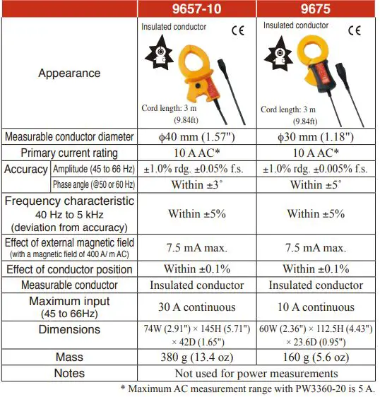
Available Recording Time
PW3360-20 and PW3360-21 with Z4001 2-GB SD card, measuring 3P3W2M wiring.
| Interval time | Save Time | Interval time | Save Time | ||
| PW3360-20 PW3360-21 (Saving of harmonic data: OFF) | PW3360-21 (Saving of harmonic data: ON) | PW3360-20 PW3360-21 (Saving of harmonic data: OFF) | PW3360-21 (Saving of harmonic data: ON) | ||
| 1 seconds | 15.9 days | 24.7 hours | 30s | 1 year | 30.8 days |
| 2 seconds | 31.9 days | 2.1 days | 1 minutes | 1 year | 61.7 days |
| 5 seconds | 79.7 days | 5.1 days | 2 minutes | 1 year | 123 days |
| 10 seconds | 159 days | 10.3 days | 5 minutes | 1 year | 308 days |
| 15 seconds | 242 days | 15.4 days | More than 10 minites | 1 year | 1 year |
The maximum recording time based on the settings can be confirmed right on the Settings screen. In any case, the maximum file size for measurement data is about 200 MB. When this is exceeded, a new file is created and saving continues.
<NOTE>
Regardless of the settings, the maximum save time of the PW3360-20, PW3360-21 is one year.
Measurement Range Configurations
| Current
Voltage Connection | CLAMP ON SENSOR 9694 (CAT III 300 V) *1 | |||||
| CLAMP ON SENSOR 9695-02 (CAT III 300 V) | ||||||
| 500.00 mA | 1.0000 A | 5.0000 A | 10.000 A | 50.000 A | ||
|
600.00 V | 1P2W | 300.00 W | 600.00 W | 3.0000 kW | 6.0000 kW | 30.000 kW |
| 1P3W 1P3W1U 3P3W2M 3P3W3M | 600.00 W | 1.2000 kW | 6.0000 kW | 12.000 kW | 60.000 kW | |
| 3P4W | 900.00 W | 1.8000 kW | 9.0000 kW | 18.000 kW | 90.000 kW | |
*1. For the 9694 sensor, the range of guaranteed accuracy is from 500 mA to 5 A, and for the 9695-02, from 500 mA to 50 A.
| Current
Voltage Connection | CLAMP ON SENSOR 9660, 9695-03 (CAT III 300 V) *2 | |||||
| CLAMP ON SENSOR 9661 | ||||||
| 5.0000 A | 10.000 A | 50.000 A | 100.00 A | 500.00 A | ||
|
600.00 V | 1P2W | 3.0000 kW | 6.0000 kW | 30.000 kW | 60.000 kW | 300.00 kW |
| 1P3W 1P3W1U 3P3W2M 3P3W3M | 6.0000 kW | 12.000 kW | 60.000 kW | 120.00 kW | 600.00 kW | |
| 3P4W | 9.0000 kW | 18.000 kW | 90.000 kW | 180.00 kW | 900.00 kW | |
*2. For the 9660 and 9695-03 sensors, the range of guaranteed accuracy is from 5 A to 100 A, and for the 9661, from 5 A to 500 A.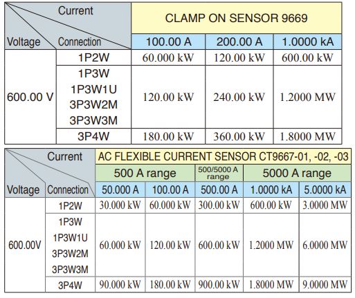
| Leak current: CLAMP ON LEAK SENSOR 9657-10, 9675 | |
| Range | 50.000 mA/100.00 mA/500.00 mA/1.0000 A/5.0000 A |
Total display range
Voltage is displayed from 5 V to 1000 V, with less than 5 V displayed as 0 V. Current is displayed from 0.4% to 130% of the selected range, with less than 0.4% displayed as 0 A Power is displayed from 0 to 130% of full scale, with 0 W displayed when voltage or current is zero. The range configurations for apparent power (S) and reactive power (Q) are the same, with units of [VA] and [var], respectively. When VT and CT ratios are set, the range configuration is the product (VT ratio × CT ratio).
Effective measurement range
For voltage, 90 to 780 V, with max. 1400 V peak. For current, 5% to 110% of the selected range with peak ±400% of range, but maximum range is ±200%. For power, 5% to 110% of the selected range. For frequency, 45 to 66 Hz.
Measurement accuracy
| Voltage | ±0.3% rdg. ±0.1% f.s. |
| Current | ±0.3% rdg. ±0.1% f.s. + clamp sensor accuracy |
| Active power | ±0.3% rdg. ±0.1% f.s. + clamp sensor accuracy (power factor = 1) |
Combined accuracy of PW3360-20 + clamp sensors
| Range | 9694 | 9695-02 | |
| 50.000 A | ― | ±0.6% rdg. ±0.12% f.s. | |
| 10.000 A | ― | ±0.6% rdg. ±0.2% f.s. | |
| 5.0000 A | ±0.6% rdg. ±0.12% f.s. | ±0.6% rdg. ±0.3% f.s. | |
| 1.0000 A | ±0.6% rdg. ±0.2% f.s. | ±0.6% rdg. ±1.1% f.s. | |
| 500.00 mA | ±0.6% rdg. ±0.3% f.s. | ±0.6% rdg. ±2.1% f.s. | |
| Range | 9660, 9695-03 | 9661 | |
| 500.00 A | ― | ±0.6% rdg. ±0.11% f.s. | |
| 100.00 A | ±0.6% rdg. ±0.12% f.s. | ±0.6% rdg. ±0.15% f.s. | |
| 50.000 A | ±0.6% rdg. ±0.14% f.s. | ±0.6% rdg. ±0.2% f.s. | |
| 10.000 A | ±0.6% rdg. ±0.3% f.s. | ±0.6% rdg. ±0.6% f.s. | |
| 5.0000 A | ±0.6% rdg. ±0.5% f.s. | ±0.6% rdg. ±1.1% f.s. | |
| Range | 9669 | ||
| 1.0000 kA | ±1.3% rdg. ±0.11% f.s. | ||
| 200.00 A | ±1.3% rdg. ±0.15% f.s. | ||
| 100.00 A | ±1.3% rdg. ±0.2% f.s. | ||
| Range | -01 CT9667-02 5000A range -03 | -01 CT9667-02 500A range -03 | |
| 5.0000kA | ±2.3% rdg. ±0.4% f.s. | ─ | |
| 1.0000kA | ±2.3% rdg. ±1.6% f.s. | ─ | |
| 500.00A | ±2.3% rdg. ±3.1% f.s. | ±2.3% rdg. ±0.4% f.s. | |
| 100.00A | ─ | ±2.3% rdg. ±1.6% f.s. | |
| 50.000A | ─ | ±2.3% rdg. ±3.1% f.s. | |
Current Display and Effective Measurement Ranges (typical)
| Conditions of guaranteed accuracy | After 30 minute warm-up, with 50/60 Hz sine wave input |
| Temperature and humidity for guaranteed accuracy | 23˚C ±5˚C (73 ± 9°F), 80%RH or less (applies to all specifications unless otherwise noted) |
| Display area of guaranteed accuracy | Effective measurement range |
| Real-time clock accuracy | Within ±0.3 sec/day (at power ON, 0°C to 50 °C) Within ±0.5 sec/day (at power ON, -10°C to 0 °C) |
| Temperature characteristic | Within ±0.1% f.s./ ˚C (except 23 ±5°C) |
| Effect of common mode voltage | Within ±0.2% f.s. (600 V AC, 50/60 Hz, between voltage input terminal and case) |
| Effect of external magnetic field | Within ±1.5% f.s. (in a magnetic field of 400 A/m rms AC, 50/60 Hz) |
| Effect of phase | Phase accuracy ±1.3° equivalent (with 50/60 Hz f.s. input) |
| Apparent power | ±1 dgt. for the calculation obtained from each measurement value |
| Reactive power | Fundamental waveform calculations ±0.3% rdg. ±0.1% f.s. + clamp-on sensor accuracy (w/power factor = 1) |
| Rms calculations From each measurement applied to calculation ±1 dgt. | |
| Energy | Active and reactive power measurement accuracies ±1 dgt. |
| Power factor | From each measurement applied to calculation ±1 dgt. |
| Frequency | ±0.5% rdg. (with 90 to 780 V sine wave input) |
| Demand value | Active and reactive power measurement accuracies ±1 dgt. |
| Demand quantity | Active and reactive power measurement accuracies ±1 dgt. |
| Pulse input | ±1 dgt. for the calculation obtained from each measurement value |
| Frequency characteristic | At 50/60 Hz fundamental waveform frequency, up to 1 kHz, ±3% rdg. ±0.2% f.s. up to 3kHz, ±10% rdg. ±0.2% f.s. For current and active power, add clamp-on sensor accuracy. Note: only for 3P3W3M wiring, add ±0.5% rdg. |
Bundled Accessories
Options
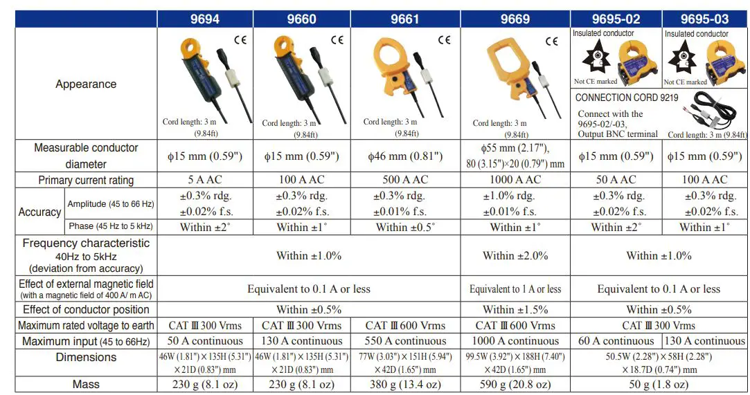
CLAMP ON SENSOR (for load current measurement)
- CLAMP-ON SENSOR 9694 (5 A AC)
- CLAMP-ON SENSOR 9660 (100 A AC)
- CLAMP-ON SENSOR 9661 (500 A AC)
- CLAMP-ON SENSOR 9669 (1000 A AC)
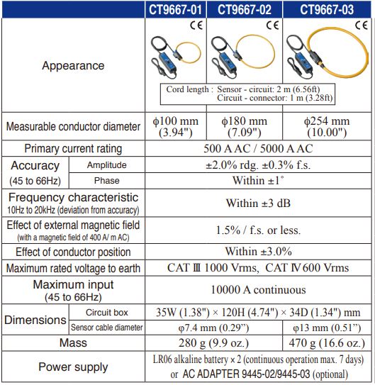
- AC FLEXIBLE CURRENT SENSOR CT9667-01 (5000 A AC)
- AC FLEXIBLE CURRENT SENSOR CT9667-02 (5000 A AC)
- AC FLEXIBLE CURRENT SENSOR CT9667-03 (5000 A AC)
- CLAMP ON SENSOR (Not CE marked) 9695-02 (50 A AC)
- CLAMP ON SENSOR (Not CE marked) 9695-03 (100 A AC)
- CONNECTION CORD 9219 (for connection to 9695-02, 9695-03)
- When purchasing the 9695-02 and 9695-03, we recommend also purchasing the separately sold 9219 Connection Cord.
Note: Company names and product names appearing in this catalog are trademarks or registered trademarks of various companies.
HEADQUARTERS
81 Koizumi,
Ueda, Nagano 386-1192 Japan
https://www.hioki.com/
All information correct as of Mar. 11, 2022. All specifications are subject to change without notice. PW3360E19-23M Printed in Japan.


