![]() DCM1500 clamp meter
DCM1500 clamp meter
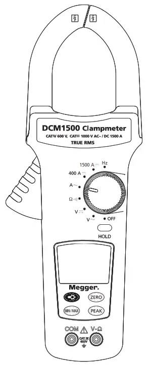
1500 A TRMS CLAMP METER
User Guide
DCM1500_UG_en-fr-es-de-nl_V04 08 2021
 Safety Information
To ensure safe operation and service of the meter, follow these instructions. Failure to observe warnings can result in severe injury or death.
- Avoid working alone so assistance can be rendered.
- To enhance safety, test leads should be disconnected from the instrument when not in use
- Do not use test leads or the clamp meter if they look damaged
- Do not use the clamp meter if the tester is not operating properly or if it is wet.
- Use the clamp meter only as specified in the instruction card or the protection provided by the clamp meter may be impaired.
- Special precautions are necessary when operating in situations where exposed live parts at dangerous voltages may be encountered. Personal protective equipment (not supplied with the instrument) should be used.
- The test leads should be disconnected from the instrument when making a current measurement.
- Use caution with voltages above 30 V AC RMS, or 60 V DC. These voltages pose a shock hazard.
- To avoid false readings that could lead to electric shock and injury, replace the battery as soon as the low battery indicator (
 ) appears.
Symbols as marked on the meter and instruction card
| Risk of electric shock See instruction card DC measurement Equipment protected by double or reinforced insulation Battery Earth AC measurement Conforms to EU directives |
![]() Caution: If the meter is used in the vicinity of equipment that generates electromagnetic interference, the display may become unstable or the measurements may be subject to large errors.
Caution: If the meter is used in the vicinity of equipment that generates electromagnetic interference, the display may become unstable or the measurements may be subject to large errors.
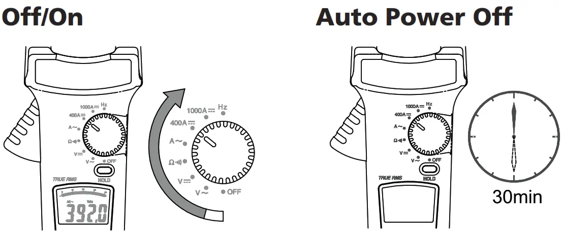
Auto Power Off disables: Press buttons (except the Hold button) then switch the rotary knob to power on the meter.
AC A / DC A
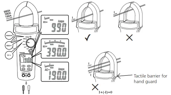
![]() CAT IV 600 V – With respect to earth for the jaw
CAT IV 600 V – With respect to earth for the jaw![]() Do not hold the meter in front of the tactile barrier.
Do not hold the meter in front of the tactile barrier.
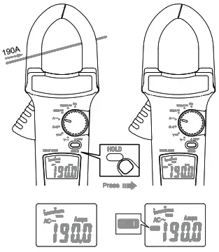
Zero
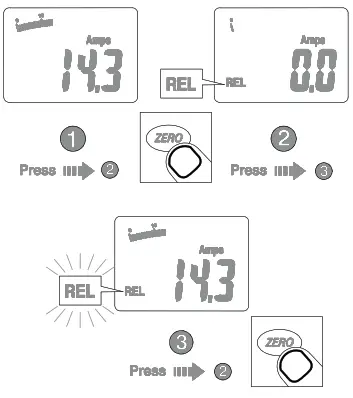
Using the Relative mode (REL), a stable value can be stored, the instrument zeroed at that point, and then any variation from that value is displayed as a direct measurement relative to the stable value.
- Make measurements and then press the ZERO button. REL: Meter stores the measured value after pressing the ZERO buttons.
- REL (flashing): The meter saves the offset value. The present value is displayed.
- Normal: Press and hold ZERO for > 2 seconds to return to normal operation and cancel the offset value.
Data Hold
Min / Max Hold
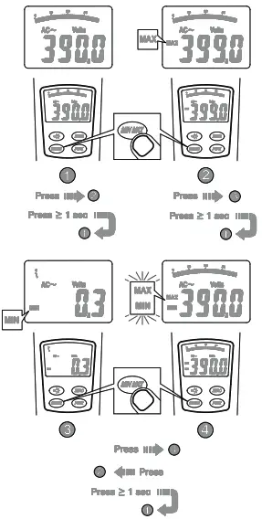
2. MAX: Meter is saving the maximum and minimum values. The maximum value is displayed.
3. MIN: Meter is saving the maximum and minimum values. The minimum value is displayed.
4. MAX MIN (flashing): Meter is saving the maximum and minimum values. The present value is displayed.
1. Normal: Press and hold MIN MAX to return to normal operation.
Battery Replacement
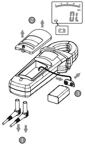
Replace battery:![]() is displayed.
is displayed.
To avoid false readings that could lead to electric shock and injury, replace the battery as soon as the low battery indicator (![]() ) appears.
) appears.
Peak Hold
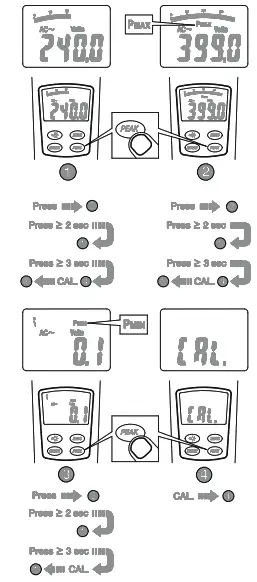
2. PMax: Meter is saving the peak maximum and minimum values. Peak maximum value id displayed.
3. PMin: Meter is saving the peak maximum and minimum values. The Peak minimum value is displayed.
4. CAL: Press and hold the PEAK button for> 3 seconds to calibrate the instrument for accurate measurement.
1. Normal: Press and hold the PEAK button to return to normal operation.
Back Light
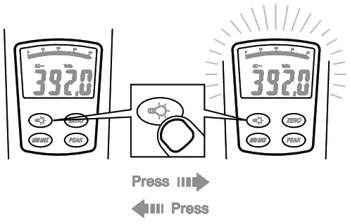
Backlight Automatic off after 60 seconds.
Specifications
General Specifications
| LCD display digits: | 3 ¾ digit large scale LCD readout. |
| Display count: | 4000 counts. |
| Measuring rate: | 1.5 times / sec. |
| Overrange display: | “OL” is displayed for “Ω” functions, shows the real value for “A” and “V” functions. |
| Automatic power off time: | Approximately 30 minutes after power on. |
| Low battery indicator: | |
| Power requirement: | 9 V PP3 / 6LR61 battery. Rechargeable batteries are not recommended for use with this instrument. |
| Battery life: | 100 hours. |
Environmental Conditions
| Indoor Use. | |
| Calibration: | |
| Operating temperature : | 0°C ~ 30°C (≤ 80 % RH) 30°C ~ 40°C (≤ 75 % RH) 40°C ~ 50°C (≤45 % RH) |
| Storage temperature: | -20 to +60°C, 0 to 80% RH (batteries not fitted). |
| Measurement Category: | (acc. to CAT IV 600 V) |
Application around and removal from UNINSULATED HAZARDOUS LIVE conductors permitted. Personal protection must always be observed.
| Operating altitude: | 2000 m (6562 ft) |
| Conductor Size: | 5 1mm diameter. |
| Pollution degree: | 2 |
| EMC: | EN 61326-1 |
| Shock vibration: | Sinusoidal vibration per MIL-T- 28800E (5 ~ 55 Hz, 3 g maximum). |
1-3 Electrical Specifications
Accuracy is ±(% reading + a number of digits) at 23 °C ± 5 °C, less than 80% R.H.
| Temperature coefficient: | 0.2 × (Specified accuracy) /°C, <18 °C, >28 °C |
| Operating temperature: | °C ~ 3 0°C (≤ 80% RH) 3 0°C ~ 4 0°C (≤ 75% RH) 40 °C ~ 50 °C (≤ 45% RH) |
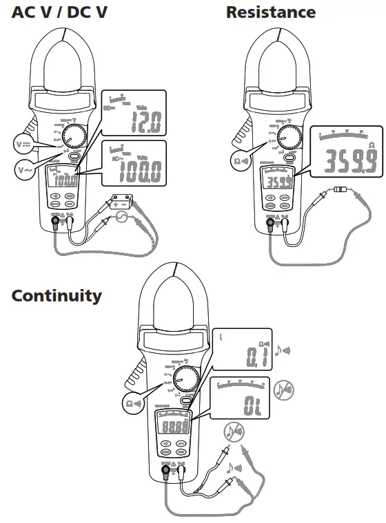
AC Volts: Auto-ranging
| Range | Resolution | Accuracy | Over-voltage protection |
| 400.0 V | 100 mV | ±(1.0% reading + 5 digits) 5 0Hz ~ 50 0Hz * | 750 V RMS |
| 750 V | 1 V |
* add 2 digits to accuracy when reading less 15% of full scale.
Input Impedance: ≥ 1MΩ// less than 10 0pF.
AC Conversion Type:
AC Conversions are ac-coupled, true RMS responding, calibrated to the RMS value of a sine wave input. Accuracies are given for sine wave at full scale and non-sine wave below half scale. For non-sine wave add the following Crest Factor corrections:
For the Crest Factor of 1.4 to 2.0, add 1.0% to accuracy.
For the Crest Factor of 2.0 to 2.5, add 2.5% to accuracy.
For the Crest Factor of 2.5 to 3.0, add 4.0% to accuracy.
Max.CF 2 @ 600 V 1.5 @ 750 V
DC Volts: Auto-ranging
| Range | Resolution | Accuracy | Over-voltage protection |
| 400.0 V | 100 mV | ± (0.7% reading + 2 digits) | 1000 V rms |
| 1000 V | 1 V |
Input Impedance: ≥1MΩ
Resistance Auto-ranging
| Range | Resolution | Accuracy | Over-voltage protection |
| 400.0 Ω | 100 mΩ | ±(1.0% reading + 3 digits) | 600 V rms |
Continuity: Built-in buzzer sound when resistance is less than 30 Ω approximately.
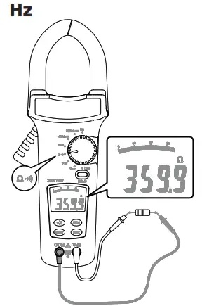
Frequency (for ACA)
| Range | Resolution | Accuracy | Over-voltage protection |
| 400 Hz | 1 Hz | ±(0.1% reading + 2 digits) | AC/DC 1000 A for 1 min. |
Min. Input Frequency: 20Hz
Sensitivity: 3A RMS for < 400Hz
ACA
| Range | Resolution | Accuracy | Frequency Response Overload | protection |
| 400 A | 0.1A | ±(1.5% reading + 5 digits) | 50 Hz – 60 Hz | 1500 A rms |
| 1000 A | 1 A | ±(1.9% reading +7 digits) | ||
| 1500 A | 1 A | ±(2.5% reading + 7 digits) | ||
| 400 A | 0.1 A | ±(1.9% reading + 5 digits) * | 61 Hz – 400 Hz | |
| 1000 A | 1 A | ±(2.5% reading + 7 digits) | 61 Hz – 200 Hz | |
| 1500 A | 1 A | ±(3.0% reading + 7 digits) |
AC Conversion Type: * add 2 digits to accuracy when reading less 15% of full scale.
AC Conversions are ac-coupled, true RMS responding, calibrated to the RMS value of a sine wave input. Accuracies are given for sine wave at full scale and non-sine wave below half scale. For non-sine waves add the following Crest Factor corrections:
For Crest Factor of 1.4 to 2.0, add 1.0% to accuracy.
For Crest Factor of 2.0 to 2.5, add 2.5% to accuracy.
For Crest Factor of 2.5 to 3.0, add 4.0% to accuracy.
Max.CF 2 @ 600 A
1.5 @ 1500 A
DCA
| Range | Resolution | Accuracy | Over voltageprotection |
| 1000 A | 0.1 A | ±(1.0% reading + 3 digits) | AC 1000 A for 1 min. |
| 400 A | 1:00 AM | ±(1.9% reading + 7 digits) | |
| 1500 A | 1:00 AM | ±(2.5% reading + 7 digits) |
Position Error: Add ±1% of LCD reading.
Auto Power Off (APO)
The meter will automatically shut itself off after approximately 30 minutes after power on.
| Peak Hold: | ±(3% reading +10 digits) * >750 V Unspecified. * >800 A Unspecified. |
| Min/Max Hold: | Add ± 15 digits to accuracy for ACA and DCA. |
Maintenance
Do not attempt to repair this meter. It contains no user-serviceable parts. Repair or servicing should only be performed by qualified personnel.
Cleaning
Periodically wipe the case with a dry cloth and detergent, do not use abrasives or solvents.
| CATIV | Measurement category IV: Equipment connected between the origin of the low-voltage mains supply outside the building and the consumer unit. |
| CATIII | Measurement category III: Equipment connected between the consumer unit and the electrical outlets. |
| CATII | Measurement category II: Equipment connected between the electrical outlets and the user’s equipment. |
![]() WEEE Directive
WEEE Directive
The crossed-out wheeled bin symbol on the instrument and on the batteries is a reminder not to dispose of them with general waste at the end of their life.
Megger is registered in the UK as a Producer of Electrical and Electronic equipment. The registration no is; WEE/DJ2235XR. Users of Megger products in the UK may dispose of them at the end of their useful life by contacting B2B Compliance at www.b2bcompliance.org.uk or by telephone at 01691 676124. Users of Megger products in other parts of the EU should contact their local Megger company or distributor.
Battery Disposal
Batteries in this product are classified as Portable Batteries under the Batteries Directive. Please contact Megger Ltd for instructions on the safe disposal of these batteries.
- For disposal of batteries in other parts of the EU contact your local distributor.
- Megger is registered in the UK as a producer of batteries.
- The registration number is BPRN01235.
- For Further information see www.megger.com
Limited Warranty
This meter is warranted to the original purchaser against defects in material and workmanship for 1 year from the date of purchase. During this warranty period, the manufacturer will, at its option, replace or repair the defective unit, subject to verification of the defect or malfunction.
This warranty does not cover fuses, disposable batteries, or damage from abuse, neglect, accident, unauthorized repair, alteration, contamination, or abnormal conditions of operation or handling.
Any implied warranties arising out of the sale of this product, including but not limited to implied warranties of merchantability and fitness for a particular purpose, are limited to the above. The manufacturer shall not be liable for loss of use of the instrument or other incidental or consequential damages, expenses, or economic loss, or for any claim or claims for such damage, expense or economic loss. Some states’ or countries’ laws vary, so the above limitations or exclusions may not apply to you.
Deceleration of Conformity
Hereby, Megger Instruments Limited declares that radio equipment manufactured by Megger Instruments Limited described in this user guide is in compliance with Directive 2014/53/EU. Other equipment manufactured by Megger Instruments Limited described in this user guide is in compliance with Directives 2014/30/EU and 2014/35/EU where they apply. The full text of Megger Instruments EU declarations of conformity are available at the following internet address: megger.com/eu-dofc.
![]()
| Megger Limited Arncliffe Road, Dover Kent CT17 9EN England T +44 (0)1 304 502101 F +44 (0)1 304 207342 E [email protected] | Megger Valley Forge Corporate Centre 2621 Van Buren Avenue Norristown, PA 19403, USA Tel: +1 (610) 676-8500 Fax: +1 (610) 676-8610 |
| Megger Z.A. Du Buisson de la Couldre 23 rue Eugène Henaff 78190 TRAPPED France T +33 (0)1 30.16.08.90 F +33 (0)1 34.61.23.77 E [email protected] | Megger GmgH Obere Zeil 2 61440 Oberursel Germany T 06171-92987-0 F 06171-92987-19 |
This instrument is manufactured in Taiwan.
The company reserves the right to change the specification or design without prior notice.
Megger is a registered trademark
DCM1500_UG_en-fr-es-de-nl_V02
www.megger.com


