KPS DCM8500PV Clamp Meter
Safety Information
Understand and follow operating instructions carefully. Use the meter only as.
WARNING
- If the equipment is used in a manner not specified by the manufacturer, the protection provided by the equipment may be impaired.
- Always use proper terminals, switch position, and range for measurements.
- To reduce the risk of fire or electric shock, do not use this product around explosive gas or in damp locations.
- Verify the Meter operation by measuring a known voltage. If in doubt, have the Meter serviced.
- Do not apply more than the rated voltage, as marked on Meter, between terminals or between any terminal and earth ground.
- To avoid false readings that can lead to electric shock and injury, replace the battery as soon as low battery indicator blinks.
Avoid working alone so assistance can be rendered.
Do not use the Tester if the Tester is not operating properly or if it is wet. Individual protective device must be used if hazardous live parts in the installation where the measurement is to be carried out could be accessible. - Disconnect the test leads from the test points before changing the position of the function rotary switch.
- Never connect a source of voltage when the function rotary switch is not in voltage position.
- When using test leads or probes, keep your fingers behind the finger guards. Use caution with voltages above 30 Vac rms, 42 Vac peak, or 60 Vdc. These voltages pose a shock hazard.
- Remove test lead from Meter before opening the battery door or Meter case. DO NOT USE the test leads when the internal white insulation layer is exposed. DO NOT USE the test leads above maximum ratings of CAT. environment, voltage and current, that are indicated on the probe and the probe tip guard cap.
- DO NOT USE the test leads without the probe tip guard cap in CAT III and CAT IV environments.
- Probe assemblies to be used for MAINS measurements shall be RATED as appropriate for MEASUREMENT CATEGORY III or IV according to IEC 61010-031 and shall have a voltage
- RATING of at least the voltage of the circuit to be measured.
- Disconnect circuit power and discharge all high-voltage capacitors before testing resistance, continuity, diodes, or capacitance.
- De-energize the installation under test or wear suitable protective clothing during fitting and removal of the Flexible Current Probe.
- Do not apply around or remove from UNINSULATED HAZARDOUS LIVE conductors, which may render electric shock, electric burn, or arc flash.
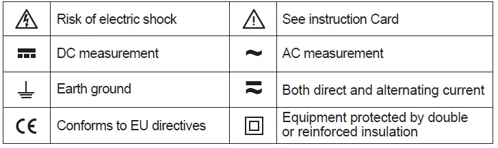
Symbols as marked on the Meter and Instruction manual
Unsafe Voltage
To alert you to the presence of a potentially hazardous voltage, when the Tester detects a voltage ≧30 V or a voltage overload (OL) in V, mV, LoZ. The ![]() symbol is displayed.
symbol is displayed.
Maintenance
Do not attempt to repair this Meter. It contains no user serviceable parts. Repair or servicing should only be performed by qualified personnel.
Cleaning
Periodically wipe the case with a dry cloth and detergent.
Do not use abrasives or solvents.
Introduction
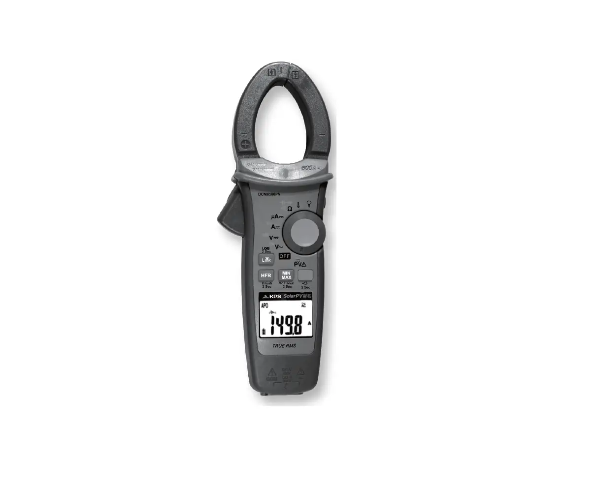
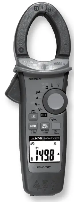
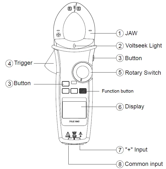
The Meter Description
Front Panel Illustration
- JAW
- Volt seek Light.
- Push-buttons.
- Trigger.
- Rotary switch for turn the Power On / Off and select the function.
- 6,000 count digital display.
- Input Terminal for Multi-function.
- Common (Ground reference) Input Terminal.
Making Basic Measurements
CAUTION
When connecting the test leads to the DUT (Device Under Test) connect the common test leads before connecting the live test leads ; when removing the test leads, remove the live test leads before removing the common test leads.
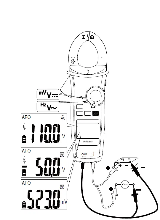
Measuring Voltage
Dial the switch to select the measuring function.
Measuring PV Voltage
Dial the switch and press the Function button to select AC/DC mode.
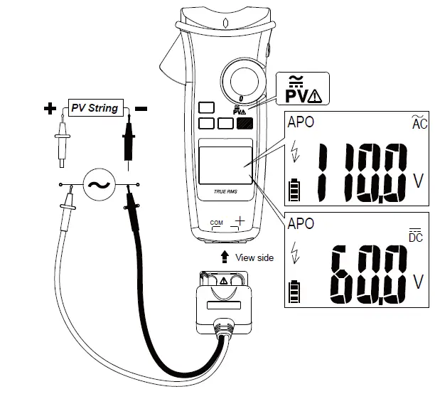
CAUTION
This function is only available with the dedicated PV test probe.
Always select correct DC / AC mode to perform high voltage measurement. This meter will flash ![]() symbol and the correct mode symbol (AC / DC) if the input voltage is different and dangerous.
symbol and the correct mode symbol (AC / DC) if the input voltage is different and dangerous.
Measuring Current
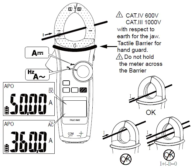
Dial the switch and press the Function button to select the measuring function. Note : Torch will be on when jaw is opened.
Measuring Resistance/Continuity/Capacitance/Diode
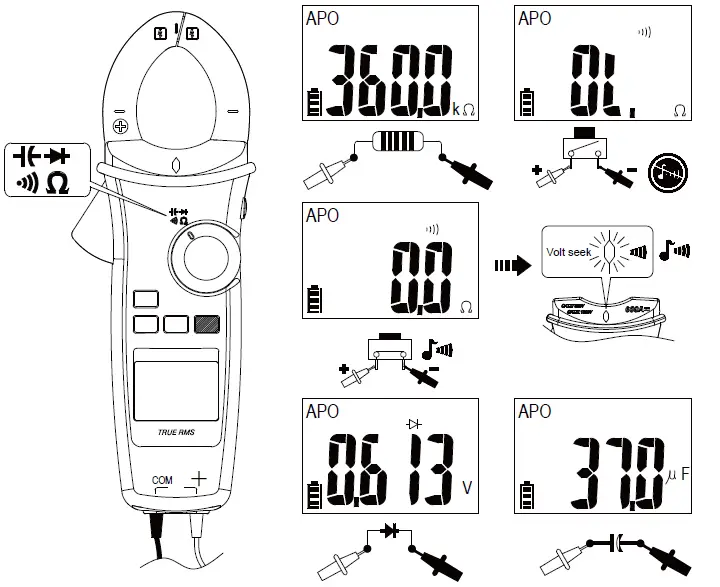
Dial the switch and press the Function button to select the measuring function.
Measuring Temperature °C / °F
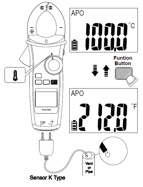
Dial the switch and press the Function button to select °C / °F mode.
Measuring μA
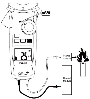
Dial the switch and press the Function button to select AC/DC mode.
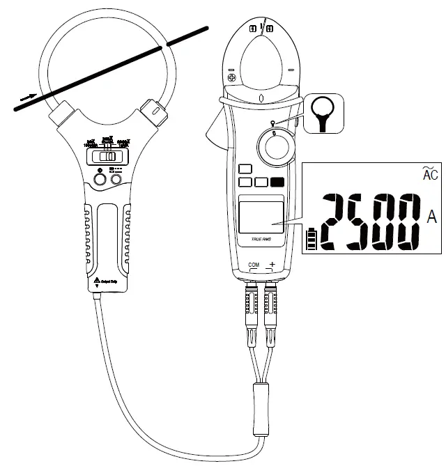
Measuring Current with Flex Clamp Meter
Keep the range of Flex Clamp meter at 3000A/3V output ratio.
 Using the Function
 Using the Function
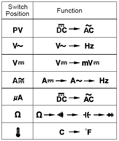
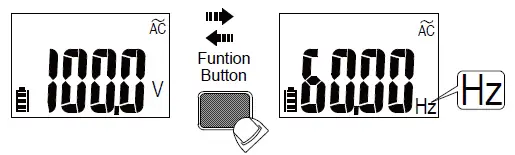
Press the Function button to change the function on the same switch position.
Measuring Frequency
Backlight
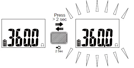
Press Function button for over 2 sec. to turn Backlight on / off.
MIN/MAX
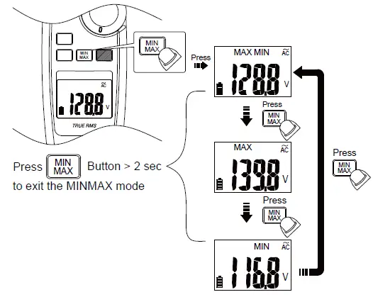
The MAX/MIN mode records the min and max input values.
When the input goes below the recorded min value or above the recorded max value, the meter records the new value. Press Hold button to pause the recording.
Volt Seek
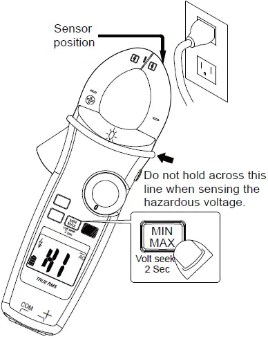
Press MIN/MAX button for over 2 sec. to enter / exit Volt Seek mode.
Press MIN/MAX button to switch high/low sensitivity.
Warning
The Volt Seek LED indicates the electric field. If the Volt Seek LED is not on, voltage could still be present.
Smart Hold
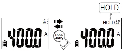
The meter will beep continuously and the display will flash if the measured signal is larger than the display reading by 50 counts.
(However, it can not detect across the AC and DC Voltage / Current).
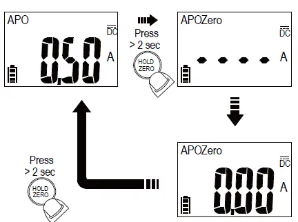
DCA ZERO
Remove the jaw from the conductor before performing DCA ZERO. Press HOLD button for over 2sec. to compensate the residual magnetism.
High-Frequency Rejection (HFR)
The High-Frequency Rejection mode equip a low pass filter in the AC measurements. The cut-off frequency (-3dB point) of low pass filter is 800Hz.
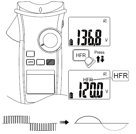
Warning
The hazardous voltage may be present even if the LCD reading is very low in HFR mode. Verify the voltage again without HFR mode
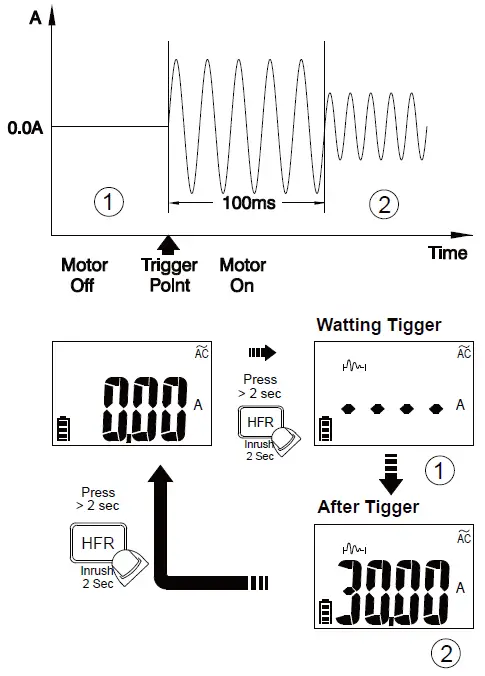
INRUSH
In inrush current mode, select the suitable measurement range by pressing HFR/INRUSH button before triggering the inrush current measurement.
Auto Power Off
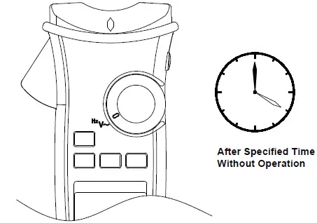
Wake up the meter by dialing the switch or pressing any button.
Time Setting of Auto Power Off
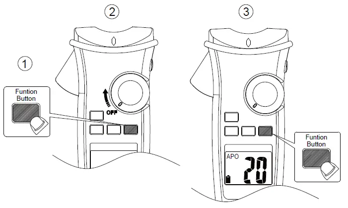
Press the function button and turn the meter on. Then press the function button to select the time. The time can be 5 minutes, 10 minutes, 20 minutes, and disabled (OFF).
Testing LCD Monitor
To turn on the meter after keeping HOLD button down.
Function of LOG Button
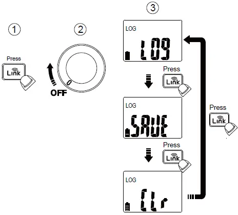
Pressing ![]() button while powering-up to select the mode – Data Logger mode, Manual Saving mode and Clear memory.
button while powering-up to select the mode – Data Logger mode, Manual Saving mode and Clear memory.
Data Logger
The meter can store up to 4000 data in memory.
Press ![]() button for more than 2 seconds to activate Data logger mode. The meter will enter Time interval setting mode.
button for more than 2 seconds to activate Data logger mode. The meter will enter Time interval setting mode.
Press ![]() button again to select time interval. The interval can be 1 second, 5 seconds, 10 seconds, 30 seconds, 60 seconds.
button again to select time interval. The interval can be 1 second, 5 seconds, 10 seconds, 30 seconds, 60 seconds.
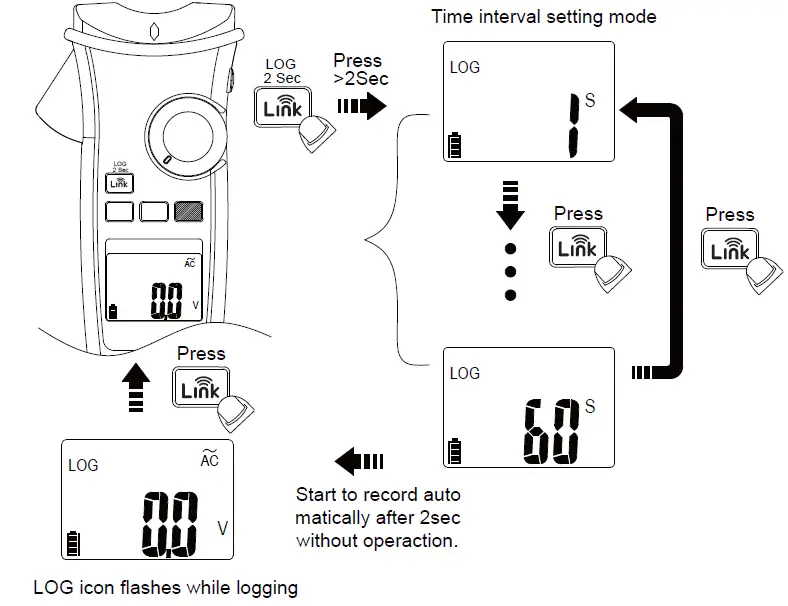
CAUTION
All stored data will be cleared next startup. Download the stored data by App first if needed.
Manual Saving Mode
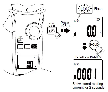
CAUTION
All stored data are saved until switching to data logger mode or executing the clear function.
The meter uses Wireless low energy (BLE) V4.0 wireless technology to transfer the real-time reading and the stored data.
The open-air communication range is up to 10m.
Download “KPS Link” App via the following QR Code. Turn on Bluetooth function of the meter and open “KPS Link” to connect the DMM. The Bluetooth icon of the meter will freeze on LCD after the connection establishes successfully.
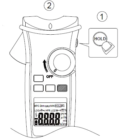
Default Temperature Units Setting
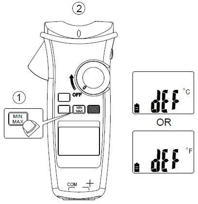
Turn on the meter after keeping MIN/MAX button down.
Low Battery and Battery Replacement
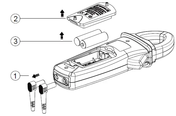
WARNING
Remove test leads from Meter before opening the battery cover or Meter case.
Specifications
General Specifications
- Display: 6000 counts.
- Overrange Indication: ”OL” or “-OL”
- Measure: Samples 3 times per second .
- Max Conductor Size of JAW: 37mm diameter
- Dimensions (W x H x D) : 62mm x 240mm x 41mm
- Weight: approx. 430g (including battery)
- Low Batteries Indication: Voltage drops below operating voltage will flash. Power Requirement : AA Size Battery x 2 (R6, LR6, 15D, 15A)
- Battery Life: 200 hours ALKALINE Battery (without Backlight)
- Operating Temperature : -10 ~10°C
- 10°C ~ 30°C (≦80% RH),
- 30°C ~ 40°C (≦75% RH),
- 40°C ~ 50°C (≦45%RH)
- Storage Temperature : -20°C to 60°C , 0 to 80% R.H. (batteries not fitted) Altitude : 6561.7 ft (2000m)
CAT Application field
| Ⅱ | The circuits directly connected to Low-voltage installation. |
| Ⅲ | The building installation. |
| Ⅳ | The source of the Low-voltage installation. |
Safety : EN 61010-1, EN 61010-2-032, EN 61010-2-033 for CAT III 1000V, CAT IV 600V, EN 61326-1
Drop Protection: 4 feet drop to hardwood on concrete floor
Vibration: Random Vibration per MIL-PRF-28800F Class 2
Pollution degree: 2
Indoor Use
Electrical Specifications
Accuracy is given as ± (% of reading + counts of least significant digit) at 23°C ± 5°C, with relative humidity Less than 80% R.H., and is specified for 1 year after calibration.
- Temperature coefficient
0.2 x (Specified accuracy) / °C, < 18°C, > 28°C - AC Function
ACV and ACA specifications are ac coupled, true R.M.S. The crest factor may be up to 3.0 as 4000 counts. Accuracy is unspecified of Square Wave.
For non-sinusoidal waveforms, Additional Accuracy by Crest Factor (C.F.) :- Add 3.0% for C.F. 1.0 ~ 2.0.
- Add 5.0% for C.F. 2.0 ~ 2.5.
- Add 7.0% for C.F. 2.5 ~ 3.0.
Max. Crest Factor of Input Signal:- 3.0 @ 3000 counts
- 2.0 @ 4500 counts
- 1.5 @ 6000 counts
Frequency Response is specified for sine waveform. LCD displays 0 counts when the reading < 20 counts.
- DC mV
Range OL Reading Resolution Accuracy 600.0mV 660.0mV 0.1mV ± (0.7% + 5D)
SInput Impedance : 10MΩ Overload Protection : AC/DC 1000V - DC Voltage
Range OL Reading Resolution Accuracy 600.0V 660.0V 0.1V ±(0.7% + 2D)
1000V 1100V 1V
SInput Impedance : 10MΩ Overload Protection : AC/DC 1000V - AC Voltage
Range OL Reading Resolution Accuracy 600.0V 660.0V 0.1V ±(1.0% + 5D)
1000V 1100V 1V
Input Impedance : 10MΩ // less than 100pF Frequency Response : 45 ~ 400Hz (Sine Wave) Overload Protection : AC/DC 1000V - PV DC Voltage
Range OL Reading Resolution Accuracy 600.0V 660.0V 0.1V ±(2.0% + 5D)
2000V 2200V 1V
Input Impedance : 10MΩ Overload Protection : AC/DC 1000V - PV AC Voltage
Range OL Reading Resolution Accuracy 600.0V 660.0V 0.1V ±(2.0% + 5D)
1500V 1600V 1V
Frequency Response : 45 ~ 400Hz (Sine Wave) Input Impedance : 10MΩ // less than 100pF Overload Protection : AC/DC 1000V - AC/DC μA
Range OL Reading Resolution Accuracy 400.0μA 440.0μA 0.1μA ±(1.0% + 3D)
4000μA 4400μA 1μA
Input Impedance : Approx. 2.2kΩ
Frequency Response : 45 ~ 400Hz (Sine Wave) Overload Protection : AC/DC 1000V - DC Current
Range OL Reading Resolution Accuracy 60.00A 66.00A 0.01A ±(2.0% + 5D)
600.0A 660.0A 0.1A
The measured value <5.0A, add 10 dgt to the accuracy. The measured value >1000A, add 0.5% to the accuracy. Overload Protection : AC/DC 600A - AC Current
Range OL Reading Resolution Accuracy 60.00A 66.00A 0.01A ±(2.0% + 5D)
600.0A 660.0A 0.1A
Add 10 dgt to the accuracy when <5.0A.
Add 0.5% to the accuracy when >1000A.
Add 1% to the accuracy when >100Hz. Frequency Response : (Sine Wave) 45 ~ 400Hz Overload Protection : AC/DC 600A - Flexible Current Probe
Range OL Reading Resolution Accuracy 300.0A 330.0A 0.1A ±(1.5% + 5D)
3000A 3300A 1A
Frequency Response : 45Hz to 400Hz
Accuracy does not include accuracy of the Flexible Current Probe. Overload Protection : AC/DC 1000V - Frequency
Range OL Reading Resolution Accuracy 100.00Hz 100.00Hz 0.01Hz ±(0.3% + 3D)
1000.0Hz 1000.0Hz 0.1Hz 10.000kHz 10.000kHz 0.001kHz
Minimum Sensitivity :
> 5V (for ACV 1Hz ~ 10kHz)
> 8A (for ACA 1Hz ~ 1kHz)
Minimum Frequency : 1Hz
Overload Protection : AC/DC 1000V and 600A - HFR (High Frequency Rejection)
Available for ACV, ACA and, Flexible Current Probe.
Add ± 4% to specified accuracy of each function and each range for 45Hz to 200Hz. Accuracy is unspecified for > 200Hz.
Cut-off Frequency (-3dB) : 800Hz - Inrush Current
Available for ACA and Flexible Current Probe.
Trigger level : ≧50d.
Add ± 3% to specified accuracy of each function and each range. - Resistance
Range OL Reading Resolution Accuracy 600.0Ω 660.0Ω 0.1Ω ±(0.9% + 5D) 6.000kΩ 6.600kΩ 0.001kΩ ±(0.9% + 2D)
60.00kΩ 66.00kΩ 0.00kΩ 600.0kΩ 660.0kΩ 0.1kΩ To get more accuracy result, short the test probes to obtain the offset. The accuracy specification is specified for the result that the offset is subtracted.
Overload Protection : AC/DC 1000V - Continuity
Builtin buzzer sounds when measured resistance is less than 20Ω and sounds off when measured resistance is more than 200Ω, Between 20Ω to 200Ω the buzzer maybe sound or off either.
Continuity Indicator : 2.7K Tone Buzzer
Response Time of Buzzer : < 100msec.
Overload Protection : AC/DC 1000V - Diode
Range OL Reading Resolution Accuracy 1.500V 1.550V 0.001V ±(0.9% + 2D) Open Circuit Voltage : Approx. 1.8V Overload Protection : AC/DC 1000V.
- Capacitance
Range OL Reading Resolution Accuracy 100.0μF 110.0μF 0.1μF ±(1.9% + 2D)
1000μF 1100μF 1μF Overload Protection : AC/DC 1000V
- VoltSeek
Voltage Range of High Sensitivity : 80V ~ 1000V (At the top edge of the jaw) Voltage Range of Low Sensitivity : 160V ~ 1000V (At the top edge of the jaw) - Temperature
Range OL Reading Resolution Accuracy -40.0°C – 400.0°C 440.0°C 0.1°C ±(1% + 20D) -40.0°F – 752.0°F 824.0°F 0.1°F ±(1% + 36D)
The accuracy does not include the accuracy of the thermocouple probe.
Accuracy specification assumes surrounding temperature stable to ±1°C. For surrounding temperature changes of ± 2°C, rated accuracy applies after 2 hours.
Overload Protection : AC/DC 1000V
ATL-PV Test Leads Instruction
Probe tip guard cap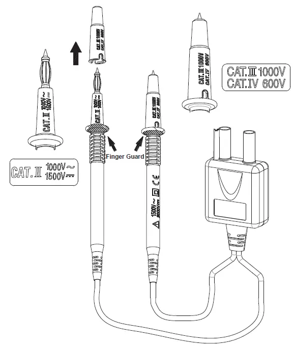
For CAT III or CAT IV environments, use the test leads with the probe tip guard cap fixed firmly. Without the probe tip guard cap, the test leads can be used in
CAT II environment ONLY.
For 1500V AC & 2000V DC measurement, This test lead can only be used in the environment that is not connected to MAINS directly.
CAUTION
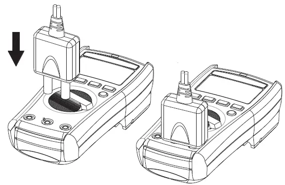
Make sure that test leads are firmly connected to the V-COM terminals of the correct instrument, and the instrument have to switch to PV mode.
- When using test leads or probes, keep your fingers behind the finger guards.
- Use caution with voltages above 30 Vac rms, 42 Vac peak, or 60 Vdc. These voltages pose a shock hazard.
- If the test lead is used in a manner not specified by the manufacturer, the protection provided by the equipment may be impaired.
- To reduce the risk of fire or electric shock, do not use this product around explosive gas or in damp locations.
- DO NOT USE the test leads when the internal white insulation layer is exposed.
- DO NOT USE the test leads above maximum ratings of CAT. environment, voltage and current, that are indicated on the probe and the probe tip guard cap.
- DO NOT USE the test leads without the probe tip guard cap in CAT III and CAT IV environments.
- DO NOT USE the test leads to measure over 1000V that is connected to MAINS directly.
Maintenance
Do not attempt to repair this test lead set. It contains no user-serviceable parts. Repair or servicing should only be performed by qualified personnel.
Cleaning
Clean the test lead with a water and mild detergent. DO NOT use abrasives or solvents and DO NOT IMMERSE in liquid.
Specification
Input Impedance: 10MΩ
Overvoltage Category: CAT 0 1500V AC, 2000V DC
CAT II 1000V AC, 1500V DC
CAT III 1000V, CAT IV 600V.
Pollution Degree 2
Exposed probe tip length : 19 mm to 4 mm (0.75 inch to 0.16 inch)
Environmental ratings : -10°C to 45°C (-4°F to 113°F), 80% R.H.
Altitude : 2000 m (6,562 ft)
Safety Standard: EN61010-031
CAT Application field
| 0 | Circuits that are not directly connected to Mains |
| Ⅱ | The circuits directly connected to Low-voltage installation. |
| Ⅲ | The building installation. |
| Ⅳ | The source of the Low-voltage installation. |
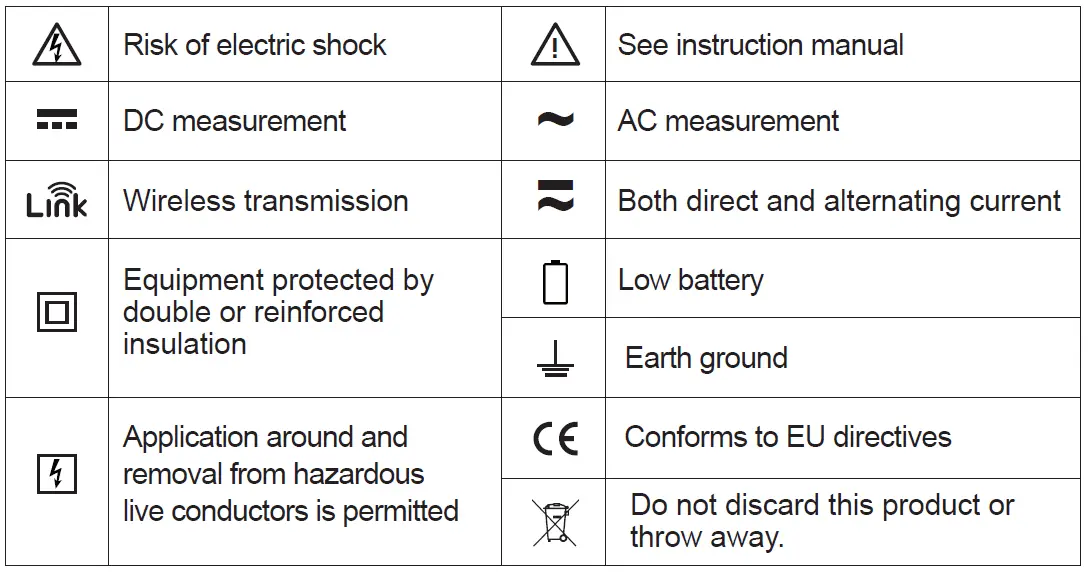
Symbols as marked on the test lead and Instruction card