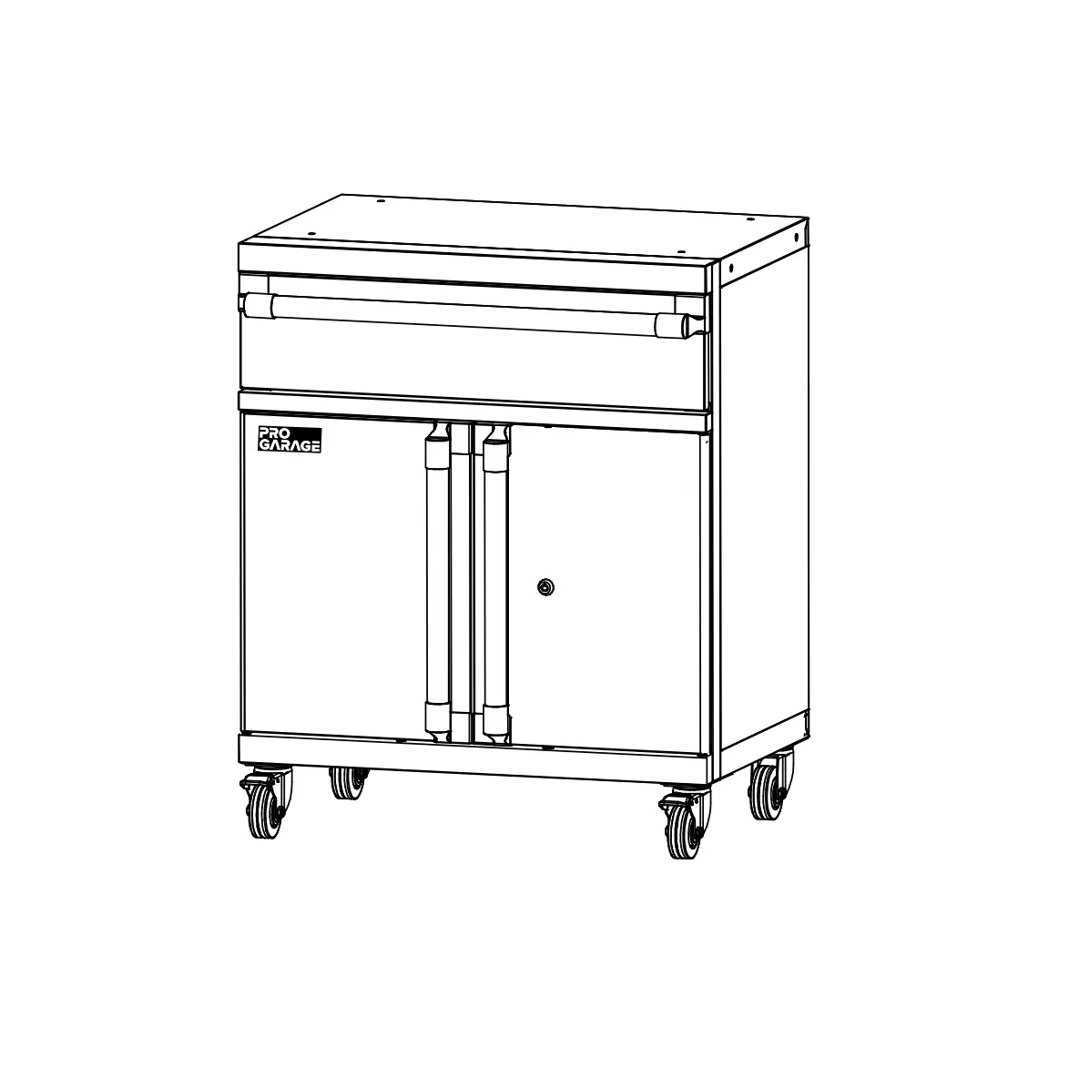
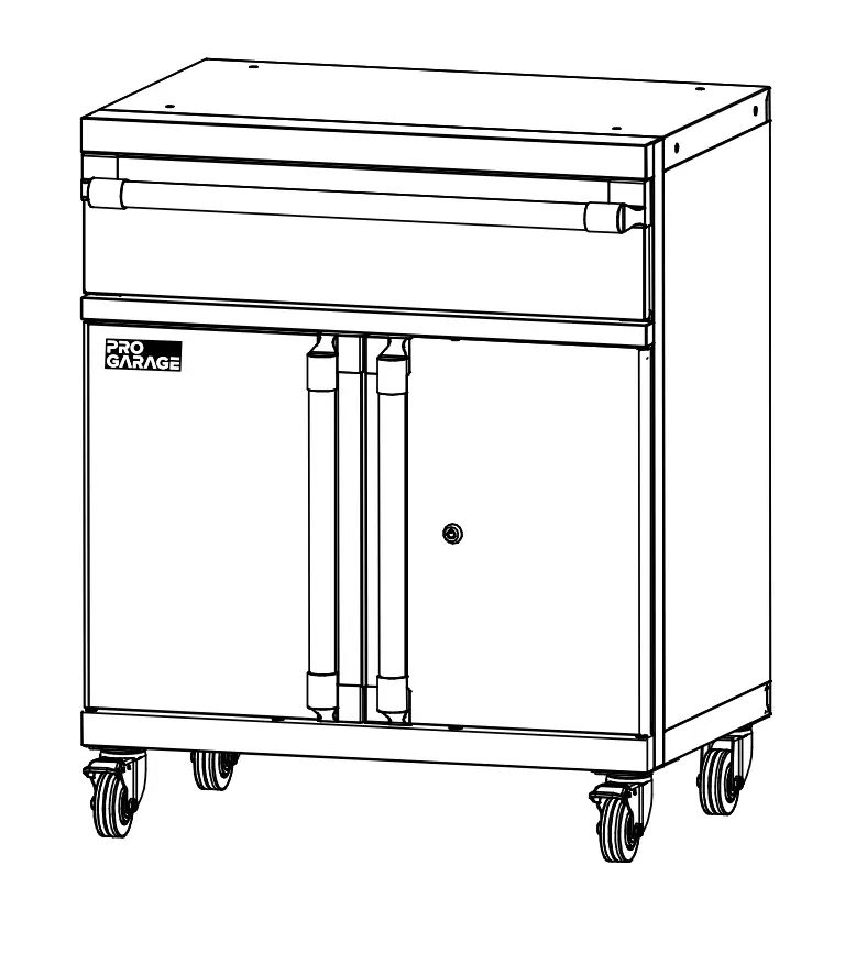
CLOSETMAID 10842 Medium Cabinet with Drawer
SAFETY PRECAUTIONS
BEFORE BEGINNING
- Please read all instructions carefully.
- Familiarize yourself with all parts (see “PARTS”) and check quantities.
- Follow all safety precautions (see “SAFETY PRECAUTIONS”).
 WARNING
- CHOKING HAZARD FOR SMALL CHILDREN. This unit contains small parts which could be a choking hazard for small children. Children should be under adult supervision at all times or serious injury could occur.
- DO NOT OVERLOAD UNIT. If any shelf, top, or bottom of unit bows or bends, it is overloaded. The shelf, top, or bottom could collapse and cause serious bodily injury and/ or damage to personal belongings. Evenly distribute loads.
- DO NOT PUT MORE THAN 5 LBS OF WEIGHT IN THE DRAWER WITHOUT ADDING ADDITIONAL WEIGHT IN THE LOWER CABINET. The unit may become unstable and tip over when the drawer is pulled out.
- DO NOT CLIMB OR STEP ON THE UNIT. The unit may become unstable and either tip or collapse. Serious bodily injury and/or damage to personal belongings may occur.
- DO NOT USE THIS UNIT AS A TELEVISION STAND. Serious bodily injury and/or damage to personal belongings may occur.
- DO NOT HANG THIS UNIT ON THE WALL. The product structure is not designed for wall hanging. Serious bodily injury, damage to personal belongings, and/or damage to the wall may occur.
- DO NOT STACK UNITS. Stacking of units can cause an unsafe tip-over hazard which may cause serious bodily injury and/or damage to personal belongings.
- DO NOT MOUNT OR ATTACH ANYTHING TO THE SIDES, REAR, OR FRONT OF THE UNIT. This can create a force which can cause the unit to tip. Serious bodily injury and/or damage to personal belongings may occur.
- PROTECT YOUR WORK SURFACE DURING ASSEMBLY.
This can prevent scratching or damage to table tops, wood floors, etc. - UNIT DOES NOT PROVIDE PROTECTION AGAINST ELECTRICAL SHOCK.
 FOLLOW INSTRUCTIONS CAREFULLY
 FOLLOW INSTRUCTIONS CAREFULLY
Please do not return product to the retail store. For product assistance and warranty information please call Consumer Affairs at 1-800-874-0008.
Manufacturer Warranty
Manufacturer will replace any missing or damaged part due to manufacturer defect for one year after purchase. Please have proof of purchase for warranty claims.
- Do not let any sharp objects touch or rub the surface of the product.
- When assembling, do not let children play around the working area.
- Please confirm all parts are correct before starting the assembly process.
- DO NOT OVERTIGHTEN. DO NOT USE POWER TOOLS. Power tools can overtighten screws and strip threads.
We recommend you hand-tighten screws.
Please note location of predrilled holes.
PARTS
TOOLS REQUIRED
- #3 Phillips Screwdriver

- 10 mm. Wrench


HARDWARE PROVIDED
| Name | Qty. | |
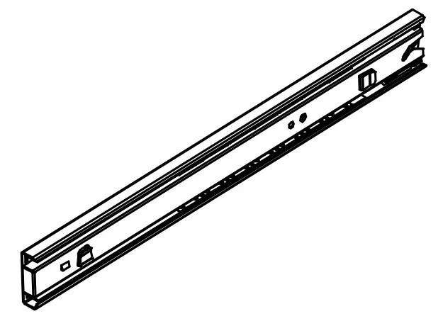
| AA | Left Drawer Glide | 1 |
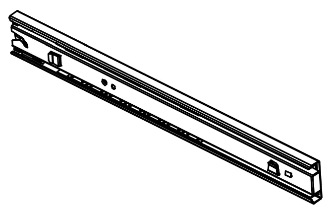
| BB | Right Drawer Glide | 1 |
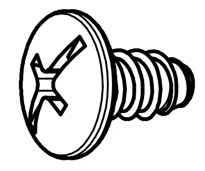
| CC | ST6.3 x 12 mm. Screw | 28 + 2 |
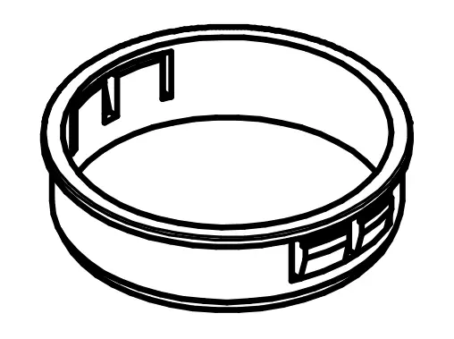
| DD | Electrical Bushing | 1 |
| EE | M6-1.0 x 12 mm. Bolt | 4 |
| FF | Key | 2 |
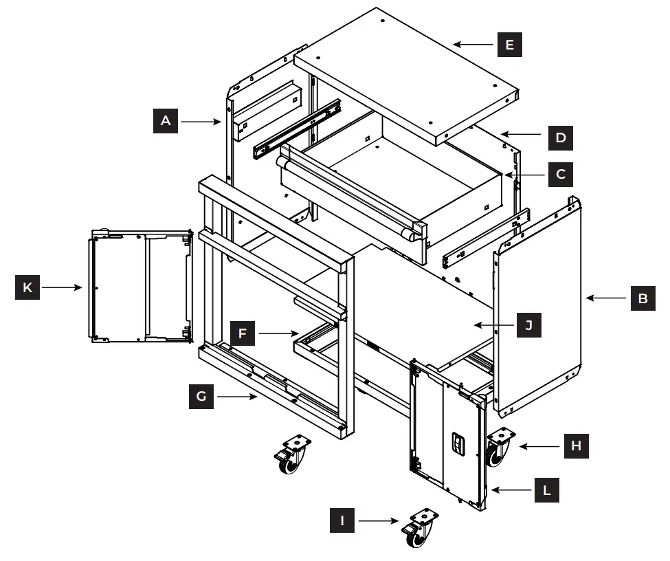
PRODUCT
| Name | Qty | Part # | Name | Qty | Part # | ||
| A | Left Side Panel | 1 | 35857 | G | Door Frame | 1 | 35864 |
| B | Right Side Panel | 1 | 35858 | H | Caster Without Brake | 2 | 20624 |
| C | Drawer | 1 | 35861 | I | Caster With Brake | 2 | 20624 |
| D | Back Panel | 1 | 35859 | J | Bottom Shelf | 1 | 35860 |
| E | Top Panel | 1 | 35854 | K | Left Door | 1 | 35862 |
| F | Bottom Panel | 1 | 35856 | L | Right Door | 1 | 35863 |
*Please note location of predrilled holes on each part
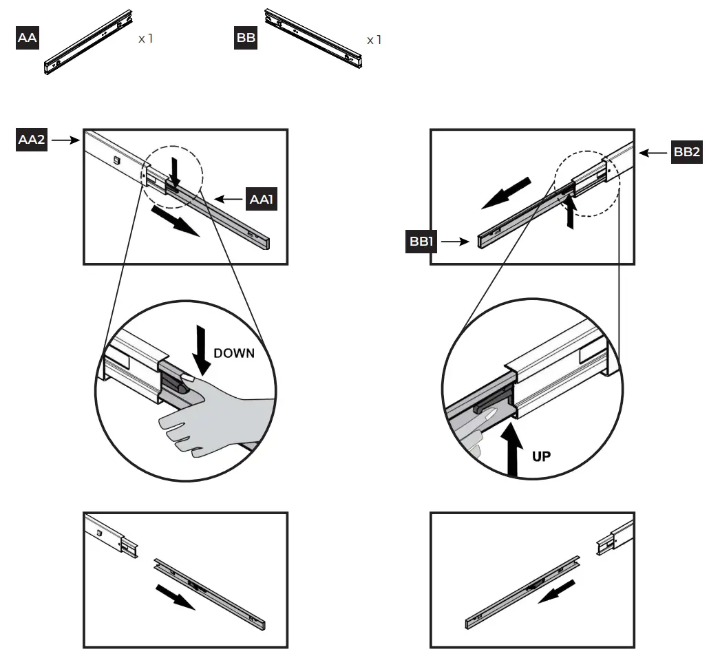
STEP 1 Remove inner drawer glides from outer drawer glides
For the left drawer glide (AA), extend the inner glide (AA1) from the outer glide (AA2). Push down on the locking tab to unlock the inner glide. Pull the inner glide out to remove.
For the right drawer glide (BB), extend the inner glide (BB1) from the outer glide (BB2). Push up on the locking tab to unlock the inner glide. Pull the inner glide out to remove.
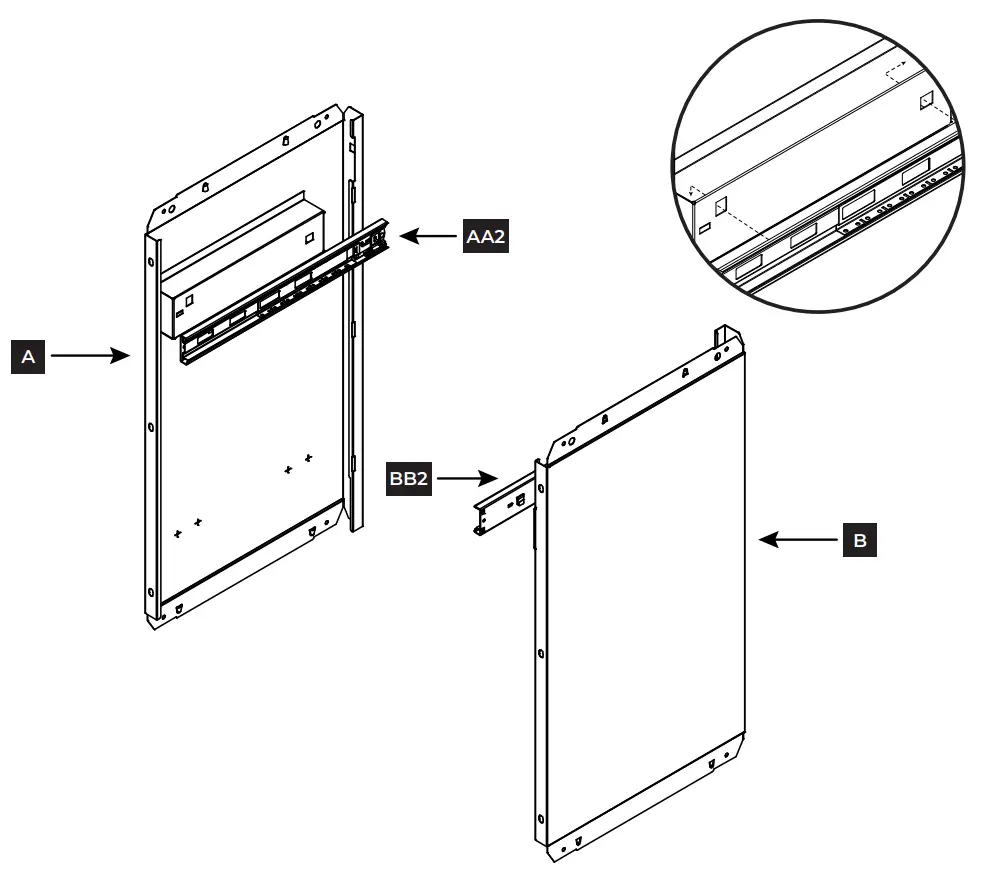
STEP 2 Attach outer glides to side panels
Align the metal tabs on the outer left glide (AA2) with the holes on the interior of the left side panel (A). With the tabs in the holes, pull the glide to the right to secure the right tab in place, and then pull down to secure the left tab. Repeat steps for the outer right glide (BB2) and right side panel (B).
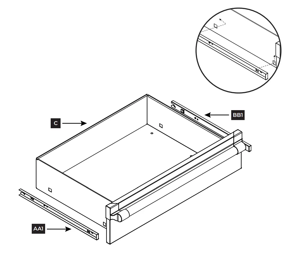
STEP 3 Attach inner glides to drawer
Align the metal tabs on the inner left glide (AA1) with the holes on the left exterior of the drawer (C). With the tabs in the holes, pull the glide to the left to secure the left tab in place, and then pull up to secure the right tab. Repeat steps for the inner right glide (BB1) on the opposite side.
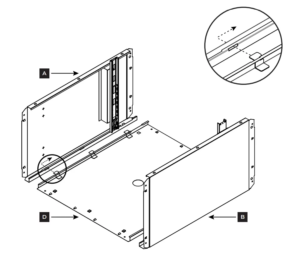
STEP 4 Attach side panels to back panel
Align both side panels (A & B) with the back panel (D) as shown.
Slide the metal tabs on the back panel (D) into the matching slots on the side panels (A & B). Pull the side panels down to secure the tabs in place.
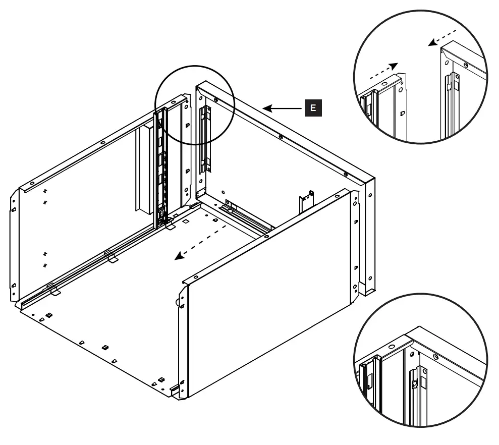
STEP 5 Attach top panel
Align top panel (E) with the top of the unit as shown.
Push down to secure into place. Make sure that all the triangular tabs on the back and side panels completely snap into place in the square holes on the top panel.
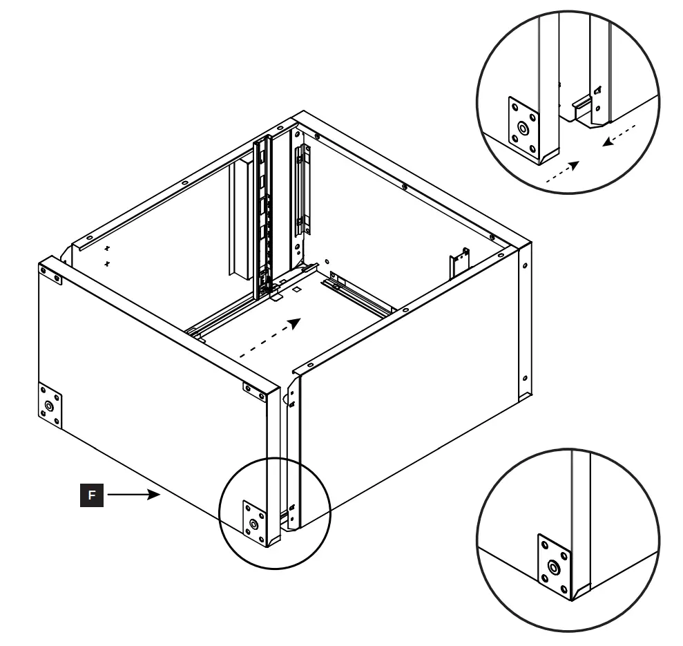
STEP 6 Attach bottom panel
Align bottom panel (F) with the bottom of the unit as shown.
Push down to secure into place. Make sure that all the triangular tabs on the back and side panels completely snap into place in the square holes on the bottom panel.
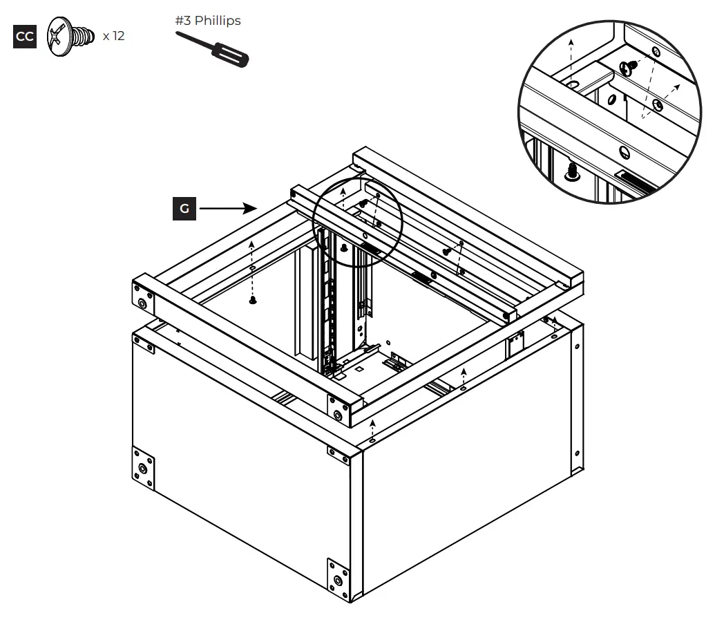
STEP 7 Attach door frame
Align the door frame (G) with the front of the unit as shown. Please note that the holes on the bottom of the door frame will match up with the upper holes on the bottom panel.
Use a #3 Phillips screwdriver to secure the door frame to the unit using twelve ST6.3 x 12 mm. screws (CC).
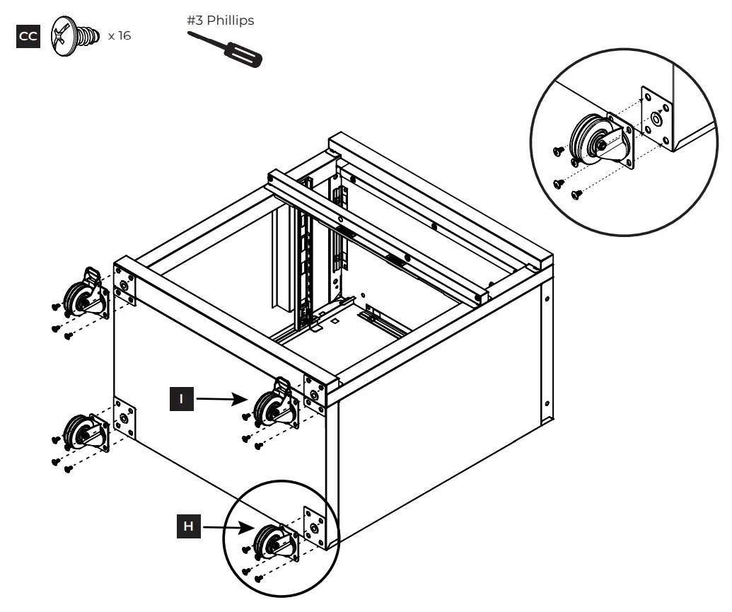
STEP 8 Attach casters
Align two casters without brakes (H) with the lower holes on the bottom panel (F). Use a #3 Phillips screwdriver to secure the casters to the unit using eight ST6.3 x 12 mm. screws (CC).
Align two casters with brakes (I) with the upper holes on the bottom panel (F). Use a #3 Phillips screwdriver to secure the casters to the unit using eight ST6.3 x 12 mm. screws (CC).
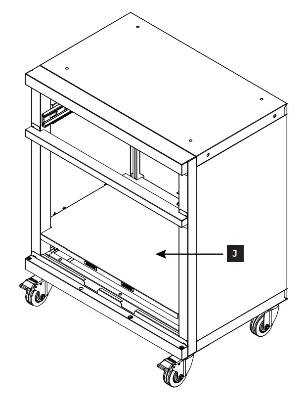
STEP 9 Attach bottom shelf
Stand the unit up on the casters.
Place the bottom shelf (J) inside the unit at the bottom. Push down to secure into place, making sure all metal tabs are connected. Please note that the bottom shelf will rest on the lowest three metal tabs on the back panel.
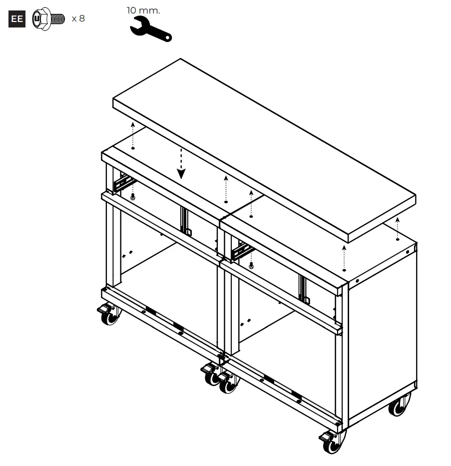
STEP 10 (Optional) Attach unit to workbench top
Note: This step is only if you are planning to attach a workbench top (sold separately). If not, skip to next step.
Place cabinets next to each other and align workbench top with the top of the units. For each cabinet, use a 10 mm. wrench to attach four M6-1.0 x 12 mm. bolts (EE) through the top panel into the workbench top.
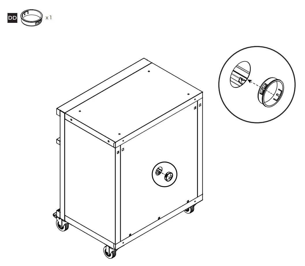
STEP 11 Attach electrical bushing
Align the electrical bushing (DD) with the large circle on the back of the unit. Push in to secure.
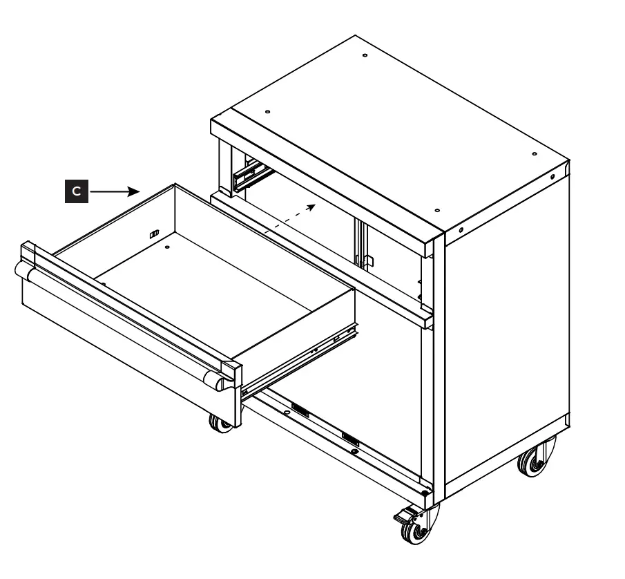
STEP 12 Insert drawer
Align the inner glides of the drawer (C) with the outer glides inside the top of the unit. Push in to attach drawer.
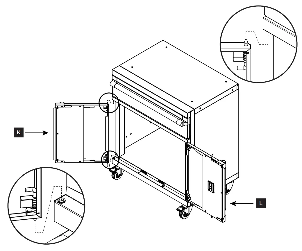
STEP 13 Attach doors
Align the right door (L) with the right side of the unit. Place the bottom lock of the door in the hole on the bottom of the door frame. Pull the top lock down, align it with the hole on the top of the door frame, and push up to lock into place. Push the bottom lock down to completely secure the door. Make sure both locks are turned inward toward the door as shown below. Please note that the right door has the slot for the key lock.
Repeat steps for the left door (K) on the left side of the unit.
Double check that all locks are in position and secure.