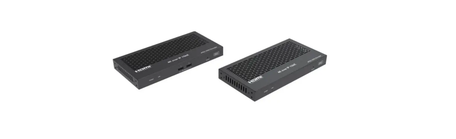
infobit iSwitch 2000 JPEG 20004K AV over IP 1GbE with Video Wall Processing
Thank you for purchasing this product
For optimum performance and safety, please read these instructions carefully before connecting, operating or adjusting this product. Please keep this manual for future reference.
Surge protection device recommended
This product contains sensitive electrical components that may be damaged by electrical spikes, surges, electric shock, lighting strikes, etc. Use of surge protection systems is highly recommended in order to protect and extend the life of your equipment.
Introduction
This product is based on JPEG2000 technology. Encoder input supports up to 4K60, audio embedding or audio out. Decoder output supports up to 4K30, audio extracting or audio in transmitted to Encoder audio out. The product supports USB2.0/KVM, 1G Ethernet, bidirectional RS-232, two-way IR control and POE function. Guest mode control of RS-232, IR, CEC supported. Built-in secondary H.265 stream which supports plenty API commands to achieve flexible configurations is useful for 3rd party control Apps to preview video content. As the H.265 stream can be accessed in a different domain from JPEG2000 main stream via tagged its LAN ID, this makes it possible to isolate the network systems of main stream which works in Video LAN and secondary stream which works in Control LAN. The system is based on Linux for software development, provides flexible control methods, that are based on the intelligent networking of 1G Ethernet Switch.
Features
- HDMI 2.0b, HDCP 2.2 compliant
- Support 18Gbps video bandwidth
- Input supports up to 4K60 4:4:4, output supports 4K30 4:4:4
- Transmit video, audio, IR , RS-232, CEC and USB signals over Ethernet
- Support unicast and multicast functions
- Support point-to-point, video matrix and video wall functions (video wall supports up to 9×9)
- Intelligent video wall class management makes it achievable of wall-in-wall or novel layout of wall configurations
- JPEG2000 Main Stream and standard H.265 codec Secondary Stream (SS)
- Support Secondary Stream VLAN tagging and parameters configuration
- Support 1G Ethernet Switch, router and hub device transmission
- Support POE function
- Flexible control through Web GUI/TCP/RS-232/IR and third-party controller
- HDMI audio formats: LPCM 2.0/5.1/7.1CH, Dolby Digital/Plus/EX, Dolby True HD, Dolby Atmos, DTS, DTS-96/24, DTS-EX DSD, DTS High Res, DTS-HD Master, DTS:X
- Smart networking design for easy and flexible installation.
Package Contents
| Qty | Item |
| 1 | 4K over IP 1GbE Encoder |
| 1 | IR Receiver cable (1.5 meters) |
| 1 | IR Blaster cable (1.5 meters) |
| 3 | 3-pin 3.81mm Phoenix connectors |
| 1 | 12V/1A Locking Power adapter |
| 2 | Mounting ears |
| 4 | Machine screws (KM3*4) |
| 1 | User Manual |
| Qty | Item |
| 1 | 4K over IP 1GbE Decoder |
| 1 | IR Receiver cable (1.5 meters) |
| 1 | IR Blaster cable (1.5 meters) |
| 3 | 3-pin 3.81mm Phoenix connectors |
| 1 | 12V/1A Locking Power adapter |
| 2 | Mounting ears |
| 4 | Machine screws (KM3*4) |
| 1 | User Manual |
SpecificationsTechnical
| Technical | |
| HDMI Compliant | HDMI 2.0b |
| HDCP Compliant | HDCP 2.2 |
| Video Bandwidth | 18Gbps |
| Video Compression Standard | JPEG2000 |
| Video Network Bandwidth | 1G |
| Video Resolution | 480i ~1080p@50/60Hz, 4K@24/30Hz, support 4K@50/60Hz input |
| Color Depth | 8/10/12-bit |
| Color Space | RGB, YCbCr 4:4:4 / 4:2:2, YUV 4:2:0 |
| HDMI Audio Formats | LPCM 2.0/5.1/7.1CH, Dolby Digital/Plus/EX, Dolby True HD, Dolby Atmos, DTS, DTS-96/24, DTS-EX DSD, DTS High Res, DTS-HD Master, DTS:X |
| Transmission Distance | 100M CAT5E/6/6A/7 |
| IR Level | 12Vp-p |
| IR Frequency | Wideband 20K – 60KHZ |
| ESD Protection | Human body model — ±8kV (Air-gap discharge) & ±4kV (Contact discharge) |
| Connection | |||
|
Encoder | Input: 1×HDMI Type A [19-pin male] 1x L/R Audio IN [3.81mm Phoenix connector] 1x IR IN [3.5mm Audio Jack] Output: 1×HDMI Type A [19-pin male] 1x L/R Audio OUT [3.81mm Phoenix connector] 1x IR OUT [3.5mm Audio Jack] Control: 1x RS-232 [3.81mm Phoenix connector] 1×LAN [RJ45 jack] 1×USB [USB TypeB] | ||
|
Decoder | Input: 1x IR IN [3.5mm Audio Jack] 1x L/R Audio IN [3.81mm Phoenix connector] Output: 1×HDMI Type A [19-pin male] 1x IR OUT [3.5mm Audio Jack] 1x L/R Audio OUT [3.81mm Phoenix connector] Control: 1×LAN [RJ45 jack] 2×USB1.1 [USB-A male] 2×USB2.0 [USB-A male] 1x RS-232 [3.81mm Phoenix connector] | ||
| Mechanical | |||
| Housing | Metal enclosure | ||
| Color | Black | ||
| Dimensions | 204mm [W] x 100mm [D] x 21.5mm [H] | ||
| Weight | TX:509g, RX:496g | ||
| Power Supply | Input: AC100 – 240V 50/60Hz, Output: DC 12V/1A (US/EU standards, CE/FCC/UL certified) | ||
| Power Consumption | Encoder: < 8W, Decoder: < 4W | ||
| Operating Temperature | 32 – 104°F / 0 – 40°C | ||
| Storage Temperature | -4 – 140°F / -20 – 60°C | ||
| Relative Humidity | 20 – 90% RH (no condensing) | ||
| Resolution / Cable Length | 4K60 – Feet / Meters | 4K30 – Feet / Meters | 1080P60 – Feet / Meters |
| HDMI IN / OUT | 16ft / 5M | 32ft / 10M | 50ft / 15M |
| The use of “Premium High Speed HDMI” cable is highly recommended. | |||
Operation Controls and Functions
Encoder Panel 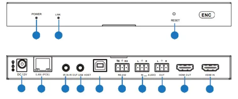
| No. | Name | Function Description |
| 1 | POWER LED | When the power is connected normally, Red LED flashes: the system is booting Red LED illuminates: booting successfully |
| 2 | LINK LED | When the system starts up normally, Green LED flashes: no signal Green LED illuminates: signal input |
| 3 | RESET button | After powering on the device, press and hold the RESET button until the POWER LED and LINK LED flash simultaneously, release the button to reset the device to factory settings. |
| 4 | DC 12V | DC 12V power input interface. |
| 5 | LAN (POE) | 1G LAN port, which can be connected to a third-party network Switch to form a distributed system. Note: When network switch delivers POE power supply, DC 12V adapter doesn’t need to apply on the unit. |
| 6 | IR IN | 12V IR signal input interface. |
| 7 | IR OUT | IR signal output interface. |
| 8 | USB HOST | USB-B connector for connecting a PC as KVM function. |
| 9 | RS-232 | Bidirectional serial signal interface. |
| 10 | AUDIO IN | Analog audio input interface, which can be embedded into the HDMI stream for pass-through over to HDMI output and Audio out on Decoder, or be loopout by the AUDIO OUT port on Encoder. |
| 11 | AUDIO OUT | Analog audio output interface. It can output the audio extracted from the HDMI IN port or the audio from the local AUDIO IN port of the Encoder. Also it can output the audio transmitted from the AUDIO IN port of the Decoder in unicast mode. |
| 12 | HDMI OUT | HDMI loop out for display. |
| 13 | HDMI IN | HDMI signal input interface. |
Decoder Panel 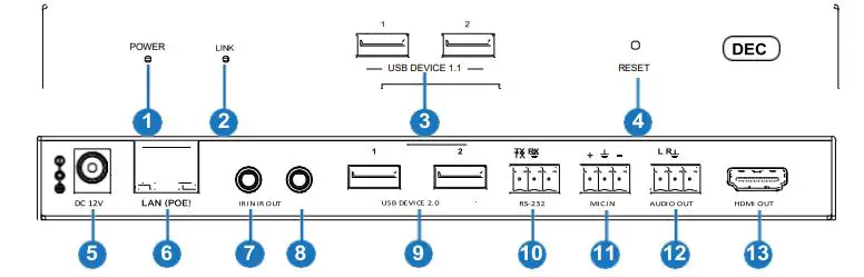
| No. | Name | Function Description |
| 1 | POWER LED | When the power is connected normally, Red LED flashes: the system is booting Red LED illuminates: booting successfully |
| 2 | LINK LED | When the system starts up normally, Green LED flashes: no signal Green LED illuminates: signal input |
| 3 | USB DEVICE 1.1 | Two USB1.1 device interface. |
| 4 | RESET button | After powering on the device, press and hold the RESET button until the POWER LED and LINK LED flash simultaneously, release the button to reset the device to factory settings. |
| 5 | DC 12V | DC 12V power input interface. |
| 6 | LAN (POE) | 1G LAN port, which can be connected to a third-party network Switch to form a distributed system. Note: When network switch delivers POE power supply, DC 12V adapter doesn’t need to apply on the unit. |
| 7 | IR IN | 12V IR signal input interface. |
| 8 | IR OUT | IR signal output interface. |
| 9 | USB DEVICE 2.0 | Two USB2.0 device interface. |
| 10 | RS-232 | Bidirectional serial signal interface. |
| 11 | MIC IN | Microphone interface. |
| 12 | AUDIO OUT | Analog audio output interface. It outputs the same audio of it on HDMI OUT in case audio format is LPCM. |
| 13 | HDMI OUT | HDMI signal output interface. |
IR Pin Definition 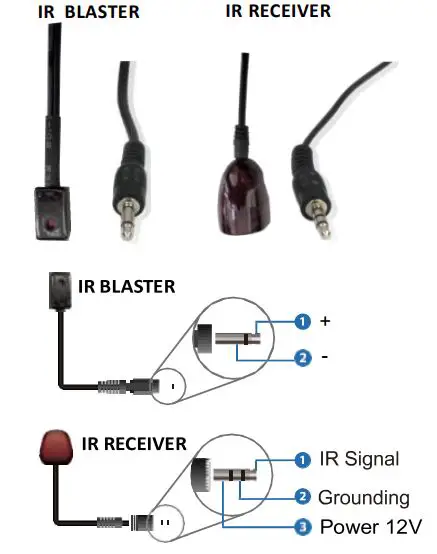
Rack Mounting Instruction
6U Rack Mounting
This product can be mounted in a standard 6U rack (Please contact your supplier for 6U rack sale). The mounting steps are as follows:
Step 1: Use included screws to fix two mounting ears on the product, as shown in the figure below: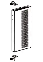 Step 2: Insert the product with mounting ears into a 6U rack (up to 10 units can be installed vertically), as shown in the figure below:
 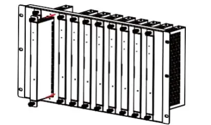 Step 3: Use screws to fix mounting ears on the rack to complete the mounting, as shown in the figure below:
1U Rack Mounting
This product also can be mounted in a standard 1U rack (up to 4 units can be installed horizontally). The mounting steps are as follows:
Step 1: Stack two products on top of each other, then use included screws to fix two 1U rack panels on the products, as shown in the figure below: 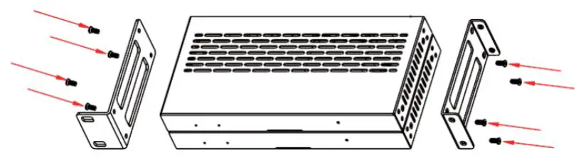 Step 2: Fix two 1U rack panels on another two stacked products in the same way, then use screws to fix two 1U rack panels together, as shown in the figure below:
 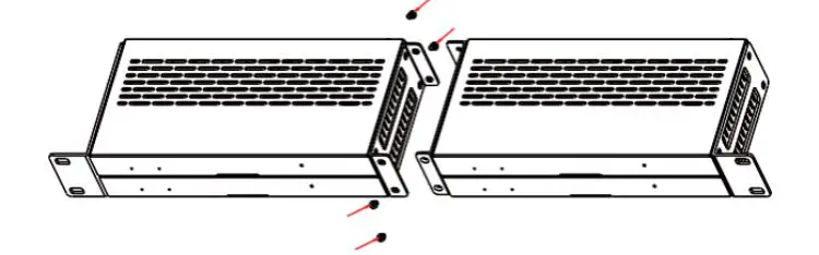 Step 3: Fasten screws between two 1U rack panels, so that four products are mounted in a 1U rack, as shown in the figure below:
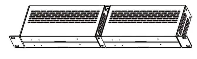
Preview Stream Introduction
Connecting Web for Control
The product supports playing Secondary Stream on computer through the corresponding software such as VLC media player, simultaneously you can access the build-in Web GUI to configure the Secondary Stream.
Follow the steps below to enter the Web GUI.
Step 1: Connect Encoder with a PC, HDMI source device and power supply. The connection diagram is shown as below. 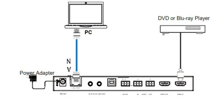 Step 2: Set the PC’s IP address to be 169.254.100.100, and the Subnet mask to be 255.255.0.0.
 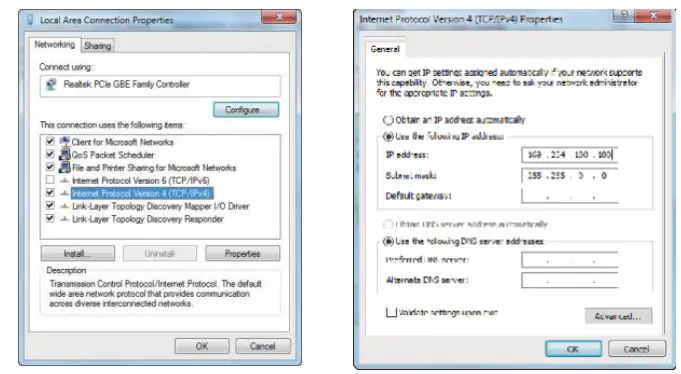 Step 3: Install a bonjour protocol checking tool (such as zeroconfService Browser) on PC to find the IP address of the Encoder. Take zeroconfServiceBrowser as an example. After opening the software, you can select “Workgroup Manager” in Services of Browser, select the Host name in Service-Instances, and find the IP address in the Address item in of Instance-Info.
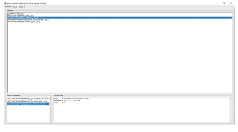
NOTE:
- The window in the lower left corner displays the Host names of all devices in the current network. Because Encoder contains a Secondary Stream chip (SS), it will be displayed as two Host names with corresponding IP addresses.
- The window in the lower right corner displays the Host name, IP address and Port number of the device.
- The Host name of Encoder starts with AST-ENC; the Host name of Decoder starts with AST-DEC; the Host name of Encoder Secondary Stream chip (SS) starts with SS-ENC.
- The Host name of Encoder contains the Host name of the Encoder Secondary Stream chip (SS).
Step 4: Set the PC’s IP address to the same network segment with IP address of the Encoder Secondary Stream (SS). (If these two IP addresses are in the same network segment, you can skip this step.)
Step 5: Input the IP address of the Encoder Secondary Stream (SS) found through the bonjour protocol checking tool into the web browser on PC. The following login interface will appear. 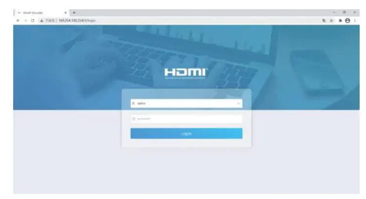
Please select the fixed user name “admin”, and Input the default password “admin”. Then click “Log In” to enter the Status page.
Status Page
The Status page provides basic information about the installed firmware version and the network settings. 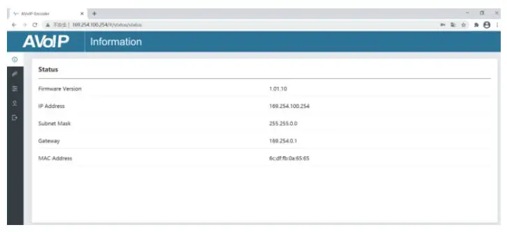
Video Page 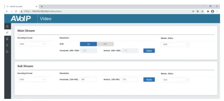
On the Video page, you can set the Main Stream and Sub Stream separately. Encoding Format can be set to H.265/H.264 according to the decoding protocol used in the 3rd party software which decodes the Secondary Stream. Pull the drop-down box to select it to take effect. The Resolution of the Main Stream includes Auto, Horizontal and Vertical. If Auto is set to ON, the resolution will follow the input resolution. At this time, Horizontal and Vertical display the current input resolution and are grayed out and cannot be set. If Auto is set to OFF, then Horizontal and Vertical can be set to the resolution of the Main Stream encoding. The horizontal range is 960~1920, the vertical range is 540~1080, and it needs to be an even number. Click the “Apply” button to take effect. The Resolution of the Sub Stream includes Horizontal and Vertical. Horizontal and Vertical can be set to the resolution of the Sub Stream encoding. The horizontal range is 320~960, the vertical range is 180~540, and it needs to be an even number. Click the “Apply” button to take effect. Bitrate is used to set the bit rate of the encoding.
Setting Page 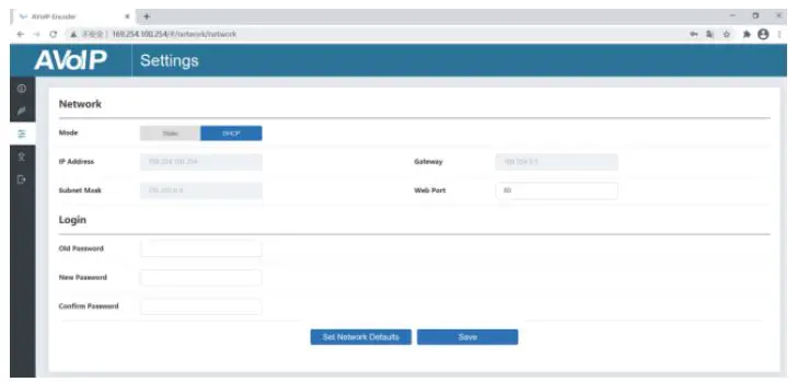
The Setting page includes two parts: Network and Login. Network can be set to Static or DHCP. When set to Static, you can enter IP address, gateway and subnet mask; When set to DHCP, the IP address, gateway and subnet mask are grayed out and cannot be edited. A DHCP server (e.g. network router) which automatically assigns IP related settings should be installed in the system. Web Port is the port of the Web page. After setting, click “Save” to take effect. After setting the IP address, the page will automatically switch to the set IP address. Click “Set Network Defaults”, it will be restored to the default DHCP state. The Web login password can be changed on the “Login” part. Enter the old password in “Old Password”, enter the new password in “New Password”, enter the new password again in “Confirm Password”, and click the “Save” button to take effect.
Update Page 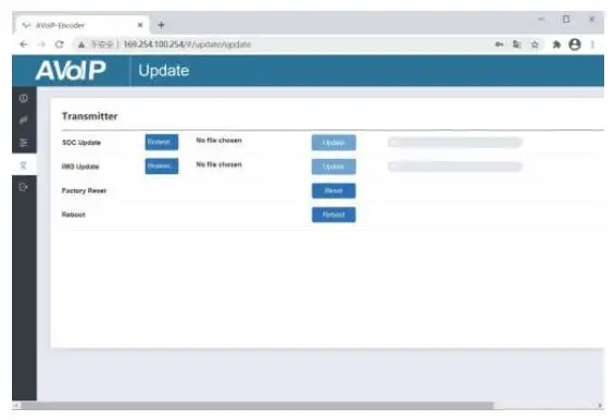
The SOC Update column is used to upgrade firmware. Click the “Browse” button to select the firmware, and then click “Update”. When the progress bar reaches 100%, the upgrade completes and the machine restarts automatically. The IMG Update column is used to download the no-signal picture, click the “Browse” button to select the picture in jpg format (the resolution of the picture should be less than or equal to 1920×1080, and the width should be aligned with 8, the height should be aligned with 2, and the size of the picture should be less than 512kB), and then click “Update”. When the progress bar reaches 100%, the download completes, and the machine takes effect without rebooting.
VLC Media Player Instruction
After the Web GUI is successfully connected, open the VLC media player on PC. Please see the following icon. 
Click “Media > Open Network Stream” 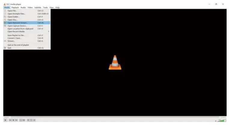
After clicking the “Open Network Stream” option, the following page will appear. 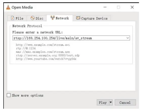
Enter a MainStream or SubStream network URL, then click “Play” button.
| Stream | Network URL |
| MainStream | rtsp://169.254.100.254/live/main/av_stream |
| SubStream | rtsp://169.254.100.254/live/sub/av_stream. |
Note: The default IP address of Secondary Stream is 169.254.100.254. When the IP address of the Encoder Secondary Stream (SS) found through the bonjour protocol checking tool is different from default IP address, please use it instead of the default IP address. On the VLC media player, you can check Secondary Main Stream or Sub Stream settings that are configured on the “Video Page” (Please refer to “7.1 Connecting Web for Control” for details). Choose “Tools>Codec information”, a pop-up window will display and show you Stream information, as shown in the figure below. 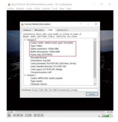
Choose “Tools>Codec information>Statistics” to check current Bitrate. Please see the following picture. 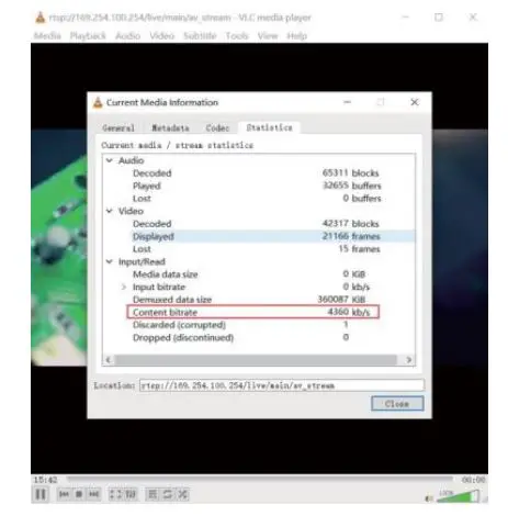
Note: The Bitrate is floating up and down when you check it. This is a normal phenomenon.
Switch Model
A network Switch used to set up the system should support below features:
- Type of layer 3/managed network Switch.
- Gigabit bandwidth.
- 8KB jumbo frame capability.
- IGMP snooping.
The following Switch models are highly recommended.
| Manufacturer | Model Number |
| CISCO | CISCO SG500 |
| CISCO | CATALYST series |
| HUAWEI | S5720S-28X-PWR-LI-AC |
NOTE:
- For the default IP mode of Control LAN port of the Controller Box is DHCP, the PC also needs to be set to “Obtain an IP address automatically” mode, and a DHCP server (e.g. network router) is required in the system.
- If there is no DHCP server in the system, 192.168.0.225 will be used as the IP address of Control LAN port. You need to set the IP address of the PC to be in the same network segment. For example, set PC’s IP address as 192.168.0.88.
- You can access the Web GUI by inputting Control LAN port IP address (192.168.0.225) or URL “http://controller.local” on your computer’s browser.
- No need to care about settings of Video LAN port of the Controller Box, they are managed by Controller automatically.
- When the Network Switch does not support PoE, the Encoder, Decoder and Controller Box should be powered by DC power adapter.
The terms HDMI and HDMI High-Definition Multimedia interface, and the HDMI Logo are trademarks or registered trademarks of HDMI Licensing LLC in the United States and other countries.


