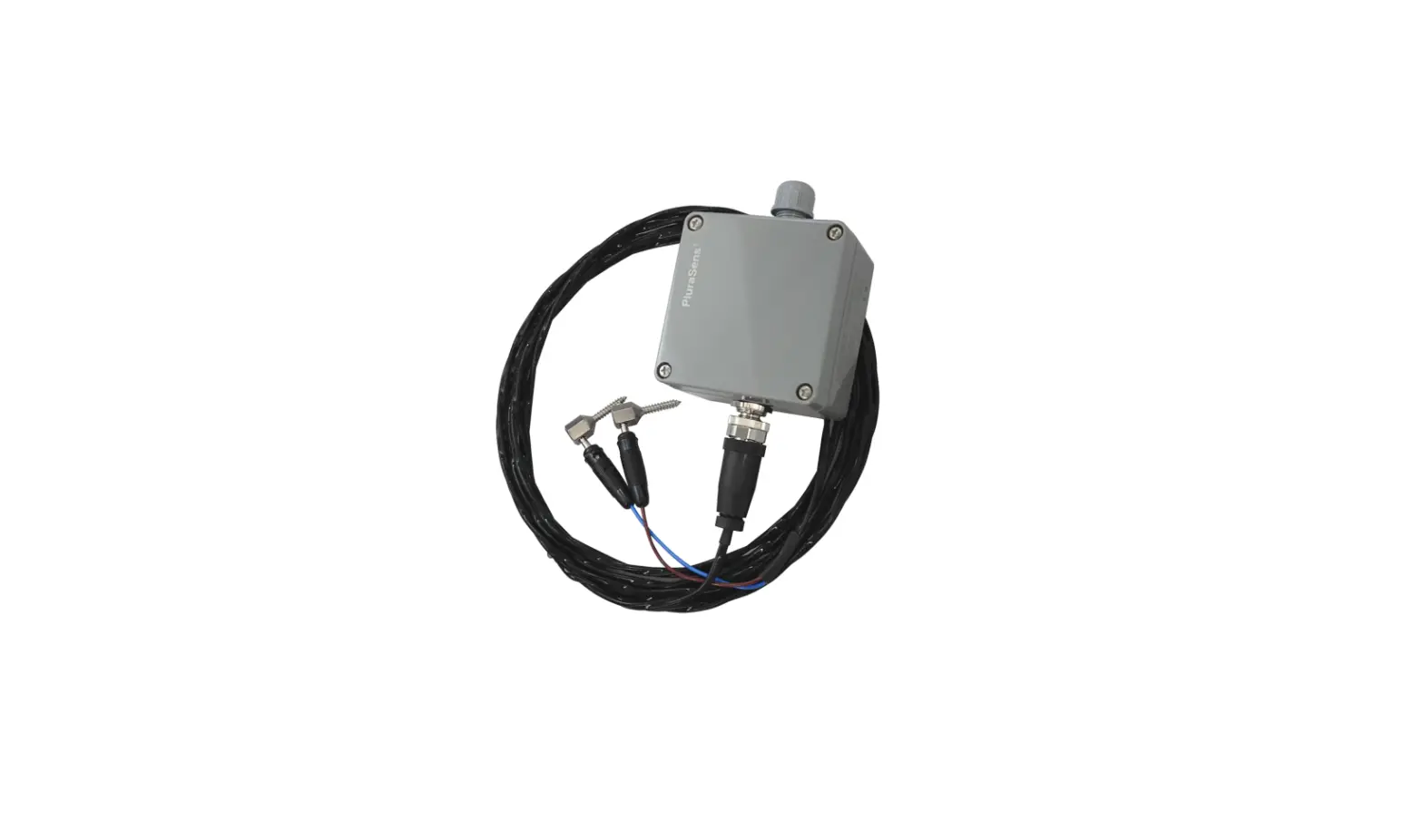
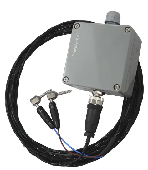
Evikon PluraSens E2353 Lumber Moisture Transmitter
Specifications
| Sensors | Conductivity sensor |
| Measurement range | 7…20 % H2O |
| Resolution | 0,01 %H2O |
| Accuracy | < ±1 %H2O |
| Self-diagnostics | Full functionality check at start-up |
| Warm-up time | ≤ 15 s |
| Response time | ~15 seconds |
| Power supply (Us) | 12…36 VDC (default), 24 VAC as option |
| Power consumption | < 0,5 W |
| Analog outputs | 2 × 4-20 mA / 0-10 V, user settable, freely configurable scales |
| Load resistance | RL < (Us – 2 V) / 22 mA for 4-20 mA RL > 250 kOhm for 0-10 V mode |
| Digital interface | RS485, Modbus RTU protocol no galvanic isolation |
| Cable connections | Screwless spring loaded terminals |
| Enclosure | Grey ABS, wall mount, protection class IP65 |
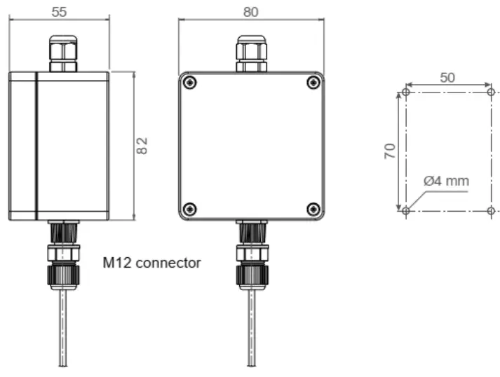
| Dimensions | H82 × W80 × D55 mm |
| Weight | <450 g |
| Operating environment | Drying kilns |
| Operating conditions | -40…+85 °C, 0…100 %RH |
| CE marking | According to 2014/30/EU and 2014/35/EU: EN 61000-6-3:2020, EN 61326-1:2013(EMC, emissions) EN 61000-6-1:2019, EN 61000-6-2:2019(EMC, Immunity) |
Product Description
- Lumber moisture transmitter E2353 is a member of the new PluraSens® family of multifunctional measurement instruments. The transmitter is intended for measurement of timber moisture during kiln drying.
- Moisture content (MC) detection is based on the measurements of electrical resistivity of lumber. The device uses robust stainless steel screw electrodes and FEP insulated connection cable to ensure the stable operation under the harsh conditions in drying kilns. Options with different length of electrodes and/or cable are available.
- Two freely configurable 4-20 mA or 0-10 V analog outputs can be used to connect the transmitter to secondary instruments. Each output can be independently assigned either to temperature or lumber moisture channel. RS485 interface with industry-standard Modbus RTU protocol allows direct Fieldbus networking of the transmitter.
Safety requirements
- Always adhere to the safety provisions applicable in the country of use.
- Do not perform any maintenance operation with the power on. Do not let water or foreign objects inside the device.
Operating conditions
The device should be used in explosion-safe (non ATEX -rated) indoor areas, without aggressive gases in the atmosphere. Allowed conditions are:
- Temperature in the range of -40…+85 °C;
- Lumber moisture in the range of 7…20% H2O;
- Atmospheric pressure in the range of 84…106,7 kPa.
Installation and connections
- Connect the connection cables to the device main unit via the M12 connector. Mark and drill four mounting holes on the wall at the chosen mounting place (see dimensional drawing).
- Unscrew four lid screws and detach the lid from the instrument. Fix the transmitter through mounting holes by screws.
- Plug the power cable and connect the analog outputs and/or digital interface terminals to the relevant devices according to the connection diagram.
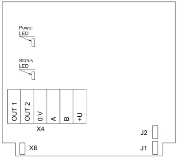
PCB without PSU and relays
| Jumpers | |
| J1 | OUT1 type (open: 4-20 mA; closed 0-10 V) |
| J2 | OUT2 type (open: 4-20 mA; closed 0-10 V) |
| X6 | Reset Modbus network parameters to default |
| X4 terminals | |
| OUT1 | 4-20 mA / 0-10 V output |
| OUT2 | 4-20 mA / 0-10 V output |
| 0V | 0 V / 24 VAC Neutral (optional) |
| A | RS485 A / Data + |
| B | RS485 B / Data – |
| +U | +24 VDC / 24 VAC Phase (optional) |
- Make certain that the cable gland is properly tightened to ensure the conformity to IP65 protection class.
- The screwless quick-connect spring terminals on the E2353 are suitable for a wide range of wires with cross-sections 0,2…1,5 mm2. The recommended wire stripping length is 8…9 mm. Push the spring loaded terminal lever, insert the wire end into the terminal hole and release the lever.
- Use twisted pair cable, e.g. LiYY TP 2×2×0,5 mm2 or CAT 5, to connect the device to the RS485 network. Use one pair for A and B wires and the second pair for common 0V and power +U wires. to connect the transmitter to the Fieldbus network. polarity must be respected when connecting to an external RS485 network.
- Overall length of all connections via RS485 interface should not exceed 1200 m.
- Place the lid back and tighten it with the four screws.
- Both analog outputs can be independently changed between 4-20 mA and 0-10 V type using jumpers J1 (OUT1) and J2 (OUT2). By closing pins on a specific jumper the related output is 0-10 V, with an open jumper the output is 4-20 mA. Power restart is required after changing the position of the jumpers.
- The output assignments and scales can be changed by Modbus commands.
Temperature compensation
For the temperature compensation to work, the transmitter has to be placed inside the kiln. As the temperature is measured around the device itself.
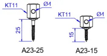
Screw electrodes
- Electrodes should be screwed in tightly, to assure proper insulation from any pollutants or liquids on the lumber surface which may decrease the accuracy of the measurement.
- It is recommended to place electrodes parallel to the grain of the lumber and at distances between 20-120 mm.
- The default length of the screw electrode is 25 mm with 15 mm variant available on request.
- The cable should be connected to the electrodes after the electrodes are tightly screwed in and removed before unscrewing the electrodes.
Connector cables
For connecting the device to the electrodes a FEP insulated cable is provided. The cable has a M12 connector on one end, to connect to the device, and two 4 mm banana plugs on the other side, to connect to the electrodes. The cable length is 5/10/15 m, depending on customers request or 5 m by default.
Delivery set
- Lumber moisture transmitter E2353
- Set of 2 screw electrodes
- Set of mounting accessories (4 screws with plastic dowels)
Order code for E2353 options
| E2353 options | Order code |
| Lumber moisture transmitter, output 4-20 mA, 7…20 %H2O | E2353-A- |
| Lumber moisture transmitter, output 0-10 V, 7…20 %H2O | E2353-U- |
| FEP cable 5 m, temperature compensator, 2 screw electrodes | E2353-C5 |
| FEP cable 10 m, temperature compensator, 2 screw electrodes | E2353-C10 |
| FEP cable 15 m, temperature compensator, 2 screw electrodes | E2353-C15 |
| Spare screw electrode, L15 mm | E2353-A23-15 |
| Spare screw electrode, L25 mm | E2353-A23-25 |
Emergency mode
The current outputs of the transmitter may be programmed via Modbus commands (register 255) to signal if the connection with the sensor is lost. The signal may be set to 3.8 mA or 21.5 mA.
Return to default settings
To reset the device’s Slave ID, baud rate and stop bit number to factory settings, proceed as follows:
- De-energize the device
- Connect the X6 jumper
- Turn on the device
- De-energize the device
- Disconnect the X6 jumper
- Turn on the device
Modbus RTU Communication
Modbus main holding registers (00xxx or 40xxx): 0-based, decimal
| Reg | RW | Description |
| 1 | R | hardware version |
| 3 | R | product serial number |
| 4 | RW | Slave ID [1…247], default 1 |
| 5 | RW | baud rate, default 9600 |
| 6 | RW | response delay [1…255] ms, default 10 |
| 7 | RW | stop bits , parity bit [1,2,3,4], default 1 |
| 16 | R | software version |
| 17 | RW | write ‘42330’ to restart |
| 146 | RW | Timber type |
| 151 | RW | Transmitter type |
| 168 | RW | integrating time constant [0…32000] s |
| 201 | RW | OUT1 parameter, 0:none, 1:T, 2:H2O |
| 202 | RW | OUT2 parameter, 0:none, 1:T, 2:H2O |
| 258 | R | temperature, °C×100, signed integer |
| 259 | R | compensated moisture, %H2O×100, integer |
| 261 | RW | OUT1 out 0%, °C / %H2O |
| 262 | RW | OUT1 out 100%, °C / %H2O |
| 263 | RW | OUT2 out 0%, °C / %H2O |
| 264 | RW | OUT2 out 100%, °C / %H2O |
Note! New Slave ID, baud rate and stop bits values apply after restart
Supported Modbus functions: 03 – read multiple registers, 06 – write single register
RS485 communication interface
![]()
Communication parameters
| Parameter | Permitted values | Default |
| Supported baud rates | 1200, 2400, 4800, 9600, 19200, 38400, 57600 | 9600 |
| Data bits | 8 | 8 |
| Parity | none / odd / even | none |
| Stop bits | 1, 2 | 1 |
| Protocol | Modbus RTU | |
| Modbus functions | 03 – Read multiple registers 06 – Write a single register | |
|
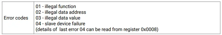
Error codes | 01 – Illegal function 02 – Illegal data address 03 – Illegal data value 04 – Slave device failure (details of last error 04 can be read from register 0x0008) | |
Modbus holding registers
Registers Reg are shown in hexadecimal 0-based format. Modbus holding register numbers MHR are shown in decimal 1-based format, and may be addressed either from 00001 or 40001 base.
| Addr | Reg / MHR | RW | Description | Supported values (dec) | Default |
| 0x0001 | 1 / 40002 / 40002 | R | Hardware version | 2353 | |
| 0x0002 | 2 / 40003 / 40003 | R | Aux parameter | – | |
| 0x0003 | 3 / 40004 | R | Product serial number | 1…65535 | – |
| 0x0004 | 4 / 40005 / 40005 | RW | Slave ID (net address) * | 1…247 ** | 1 |
| 0x0005 | 5 / 40006 / 40006 | RW | Baud Rate * | 1200, 2400, 4800, 9600, 19200, 38400, 57600 | 9600 |
| 0x0006 | 6 / 40007 / 40007 | RW | Response delay, ms | 1…255 | 10 |
|
0x0007 |
7 / 40008 |
RW |
Stop bits, parity bit * | 1 – no parity bit, 1 stop bit (default after factory reset) 2 – no parity bit, 2 stop bits 3 – odd parity, 1 stop bit 4 – even parity, 1 stop bit NOTE: 3 and 4 are available starting from the Software version 0x218 (dec. 536) |
1 |
| 0x0010 | 16 / 40017 | R | Software version | – | |
| 0x0011 | 17 / 40018 / 40018 | RW | Restarts counter | write ‘42330’ to restart device | – |
| 0x0014 | 20 / 40021 | R | Counter of I2C errors | 0…65535 | – |
| Addr | Reg / MHR | RW | Description | Supported values (dec) | Default |
| 0x0092 | 146 / 40147 | RW | Timber type | 0…10 | 0 |
| 0x00A2 | 162 / 40163 | RW | Zero adjustment for ADC, ADC units | -32768…+32767 | 0 |
| 0x00A5 | 165 / 40166 | RW | Zero adjustment for moisture data, %H2O x 100 | -32768…+32767 (-327.68…+320.767 %H2O) | 0 |
| 0x00A7 | 167 / 40168 | RW | Change rate limit for moisture data, %H2O x 100/s | 0…32000, (0.01…320 %H2O/s) 0=no limit | 0 |
| 0x00A8 | 168 / 40169 | RW | Integrating filter time constant, s | 1…32000 (seconds), 0 – no filter | 0 |
|
0x00C9 |
201 / 40202 |
RW |
Parameter tied to analog output 1 | 0 – none 1 – temperature 2 – moisture 9 – forced Modbus control, value set in MHR / 40204 |
2 |
|
0x00CA |
202 / 40203 |
RW | Parameter tied to analog output 2 | 0 – none 1 – temperature 2 – moisture 9 – forced Modbus control, value set in MHR / 40205 |
1 |
| 0x00CB | 203 / 40204 | RW | Forced value for analog output 1*** | 0…1000 (0,0%…100,0% of output scale) | 0 |
| 0x00CC | 204 / 40205 | RW | Forced value for analog output 2*** | 0…1000 (0,0%…100,0% of output scale) | 0 |
|
0x00D3 |
211 / 40212 |
RW |
Parameter tied to relay RE1 | 0 – none 1 – temperature 2 – moisture 9 – control by Modbus control, state set in MHR / 40214 |
0 |
|
0x00D4 |
212 / 40213 |
RW |
Parameter tied to relay RE2 | 0 – none 1 – temperature 2 – moisture 9 – control by Modbus control, state set in MHR / 40215 |
0 |
| 0x00D5 | 213 / 40214 | RW | Forced state for relay RE1*** | 0 – off, 1 – on | 0 |
| 0x00D6 | 214/ 40215 | RW | Forced state for relay RE2*** | 0 – off, 1 – on | 0 |
| 0x00D7 | 215 / 40216 | RW | Switching delay for relay RE1 | 0…1000 (s) | 0 |
| 0x00D8 | 216 / 40217 | RW | Switching delay for relay RE2 | 0…1000 (s) | 0 |
| 0x00D9 | 217 / 40218 | RW | Minimal on/off time for relay RE1 | 0…1000 (s) | 0 |
| 0x00DA | 218 / 40219 | RW | Minimal on/off time for relay RE2 | 0…1000 (s) | 0 |
| Addr | Reg / MHR | RW | Description | Supported values (dec) | Default |
|
0x00DB |
219 / 40220 |
RW |
Control logic for relay RE1 | 0 – none 1 – relay on at high values 2 – relay on at low values 3 – relay on at values within the range 4 – relay on for the values out of the range |
0 |
|
0x00DC |
220 / 40221 |
RW |
Control logic for relay RE2 | 0 – none 1 – relay on at high values 2 – relay on at low values 3 – relay on at values within the range 4 – relay on for the values out of the range |
0 |
| 0x00DD | 221 / 40222 | RW | LOW setpoint for relay RE1 | -32768…+32767 (-327.68…+327.67 %H2O / -327.68…+327.67 °C) | 0 |
| 0x00DE | 222 / 40223 | RW | HIGH setpoint for relay RE1 | -32768…+32767 (-327.68…+327.67 %H2O / -327.68…+327.67 °C) | 0 |
| 0x00DF | 223 / 40224 | RW | LOW setpoint for relay RE2 | -32768…+32767 (-327.68…+327.67 %H2O / -327.68…+327.67 °C) | 0 |
| 0x00E0 | 224 / 40225 | RW | HIGH setpoint for relay RE2 | -32768…+32767 (-327.68…+327.67 %H2O / -327.68…+327.67 °C) | 0 |
| 0x00FD | 253 / 40254 | R | ADC raw, MSW | ||
| 0x00FE | 254 / 40255 | R | ADC raw, LSW | ||
|
0x00FF |
255 / 40256 |
RW |
Sensor, analog outputs, LED and buzzer status | bit[0]=0/1 – sensor present/absent, read-only! bit[1]=0/1 – analog outputs deactivated/activated, bit[2]= 0/1 – in case of sensor absent, turn signaling off/on analog output1, bit[3]=0/1 – in case of sensor absent, turn on signaling with low current/high current on analog output1; if bit[2]==0 this bit will be ignored, bit[4]=0/1 – in case of sensor absent, turn signaling off/on analog output2 bit[5]=0/1 – in case of sensor absent, turn on signaling with low current/high current on analog output2; if bit[4]==0 this bit will be ignored, bit[6]=0/1 – current/voltage output detected on output1 |
0x300 |
| (only if bit[1] = 1), read-only! bit[7]=0/1 – current/voltage output detected on output2 (only if bit[1] = 1), read-only! bit[8]=0/1 – LED deactivated/activated, bit[9]=0/1 – buzzer deactivated/activated, bit[10]=0/1 – LED is on/off in normal condition | |||||
| 0x0100 | 256 / 40257 | R | Resistance of wood, megaohms | 0. 65.535 gigaohms | |
| 0x0101 | 257 / 40258 | R | Relative moisture of wood, not compensated, unit=0.01% | 0…10000 (0…100%) | |
| 0x0102 | 258 / 40259 | R | Measured temperature, °C×100 | signed integer, -4000…+12500 (-40,00…+125,00 °C) | |
| 0x0103 | 259 / 40260 | R | Relative moisture of wood, compensated, averaged, unit=0.01% | 0…10000 (0…100%) | |
| 0x0105 | 261 / 40262 | RW | 0% value of analog output1, °C / %H2O | -32768…+32767 (-32768…+32767 %H2O / -32768…+32767 °C) | 0 |
| 0x0106 | 262 / 40263 | RW | 100% value of analog output1, °C / %H2O | -32768…+32767 (-32768…+32767 %H2O / -32768…+32767 °C) | 100 |
| 0x0107 | 263 / 40264 | RW | 0% value of analog output2, °C / %H2O | -32768…+32767 (-32768…+32767 %H2O / -32768…+32767 °C) | 0 |
| 0x0108 | 264 / 40265 | RW | 100% value of analog output2, °C / %H2O | -32768…+32767 (-32768…+32767 %H2O / -32768…+32767 °C) | 100 |
- The new value is applied after restart.
- Broadcast slave ID 0 can be used to assign a new ID to the instrument with an unknown ID. When addressing by ID 0 the device shall be the only Modbus instrument in the network. The device will not respond to the Master command when addressed by ID 0.
- This value is dynamic and not kept in EEPROM after a restart.
E2353 series Timber Types
Wood types and their corresponding register values.
| Wood type | Corresponding register value |
| Finnish Pine | 0 |
| Nordic Pine | 1 |
| Finnish Spruce | 2 |
| Nordic Spruce | 3 |
| Finnish Birch | 4 |
| Nordic Birch | 5 |
| Danish Oak | 6 |
| Middle European Oak | 7 |
| Alder | 8 |
| Larch v1 | 9 |
| Larch v2 | 10 |
Warranty
This product is warranted to be free from defects in material and workmanship for a period of one year from the date of the original sale. During this warranty period, the Manufacturer will, at its option, either repair or replace a product that proves to be defective. This warranty is void if the product has been operated in conditions outside ranges specified by the Manufacturer or damaged by customer error or negligence or if there has been an unauthorized modification.
Manufacturer contacts
Evikon MCI OÜ
Teaduspargi 7/9, Tartu
50411 Estonia
[email protected]
www.evikon.eu


