Inhand 485 Light Temperature and Humidity Transmitter

product description
product description
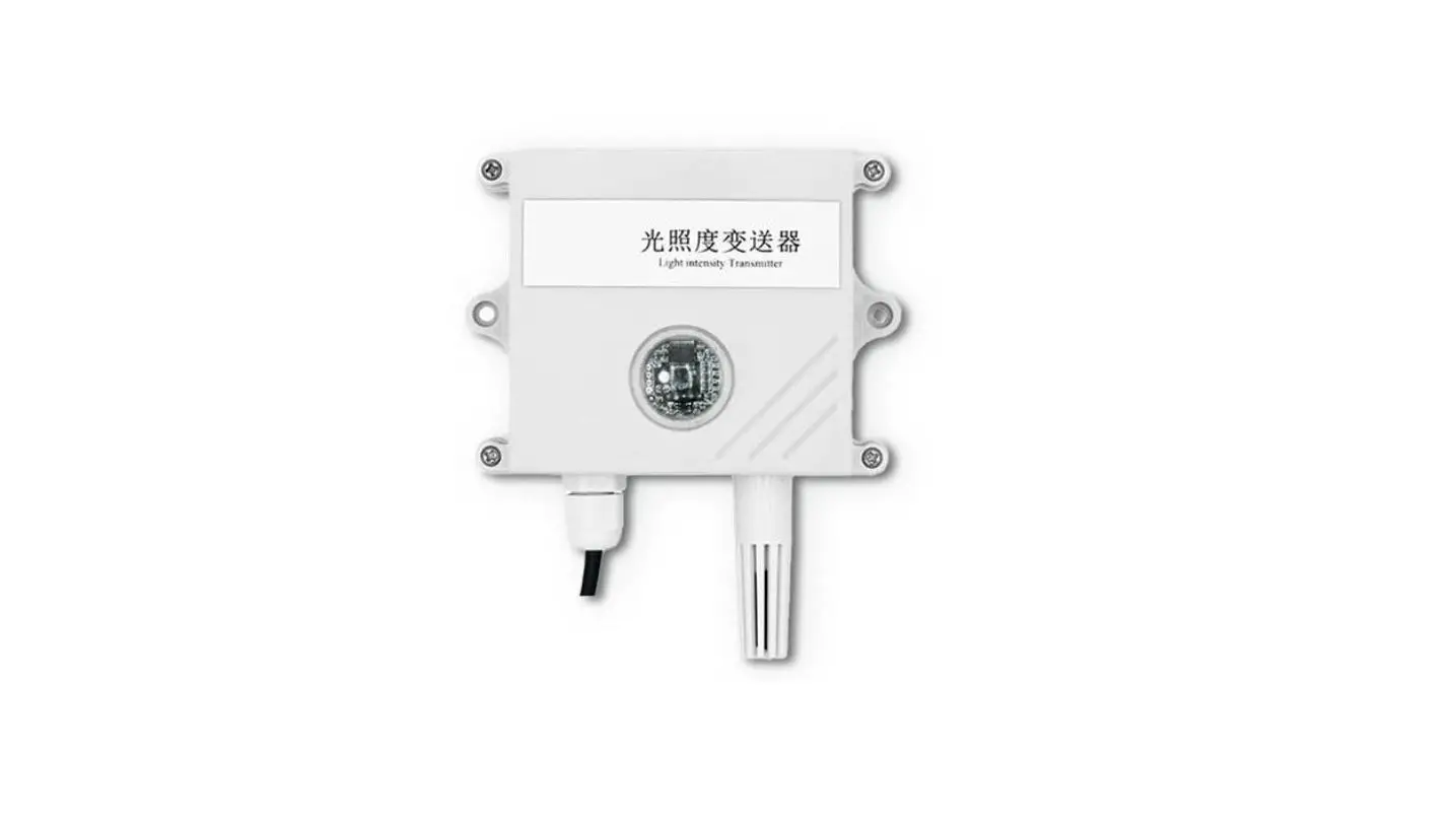
It is a high-precision photosensitive transmitter, the output value measurement unit is Lux, the device adopts a wall-mounted waterproof shell, wall-mounted installation, and high protection level. 485 communication, standard ModBus-RTU communication protocol, communication address and baud rate can be set, the longest communication distance is 2000 meters, the product power supply is 10-30V wide voltage power supply, mainly used in agricultural greenhouses, flower cultivation greenhouses, agricultural fields, electronics Equipment production lines and other occasions that require light intensity monitoring.
Features
- High-precision illuminance detection measurement range of 0-6 million Lux, 0-20 million Lux optional.
- 485 communication, standard ModBus-RTU communication protocol, communication address and baud rate can be set, the longest communication distance is 2000 meters
- Wall-mounted waterproof shell, high protection level, can be used in outdoor or harsh on-site environment
- 10-30V DC wide voltage power supply
Main Specifications
| DC power supply (default) | 10-30VDC | |
| Maximum power consumption | 0.4W | |
|
Accuracy | humidity | ±3%RH(5%RH~95%RH,25℃) |
| temperature | ±0.5℃(25℃) | |
| Light intensity | ±7% (25℃) | |
| Light intensity range | 0-65535Lux;0-200000Lux | |
| Temperature and humidity range | -40℃~+60℃,0%RH~80%RH | |
| Long-term stability | temperature | ≤0.1℃/y |
| humidity | ≤1%/y | |
| Light intensity | ≤5%/y | |
|
Response time | temperature | ≤18s (1m/s Wind speed) |
| humidity | ≤6s (1m/s Wind speed) | |
| Light intensity | 0.1s | |
product model
| RS- | Company code | ||||
| GZ- | Light intensity transmission sensor | ||||
| GZWS- | Light intensity, temperature and humidity three in one transmission, sensor | ||||
| N01- | RS485 (M0dbus protocol) | ||||
| 2- | Wall-mounted king character shell | ||||
| 65535 | Range 0-65535 | ||||
| 200000 | Range 0-20W | ||||
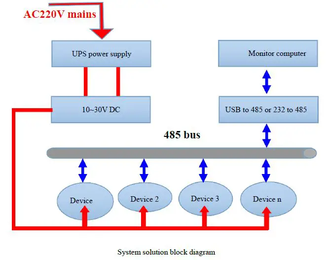
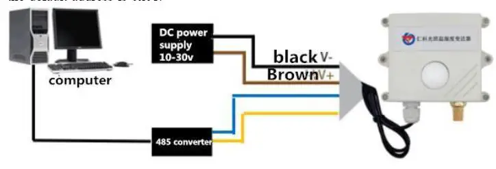
System framework diagram
2. Equipment installation instructions
Check before installation
Equipment List:
- 1 transmitter device
- USB to 485 (optional)
- Warranty card, certificate, wiring instructions, etc.
installation method

Interface Description
Wide voltage power input can be 10 ~ 30V. When connecting the 485 signal line, please note that the A / B lines cannot be reversed, and the addresses of multiple devices on the bus must not conflict.
| Thread color | Explanation | |
| power supply | brown | Positive power supply (10 ~ 30V DC) |
| black | Negative power supply | |
| Communication | yellow | 485-A |
| blue | 485-B |
485Field wiring instructions
When multiple 485 model devices are connected to the same bus, there are certain requirements for field wiring. For details, please refer to Examination data package “485 equipment field wiring manual”. 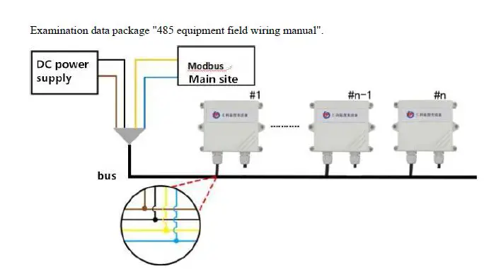
3. Configuration software installation and use
Software selection
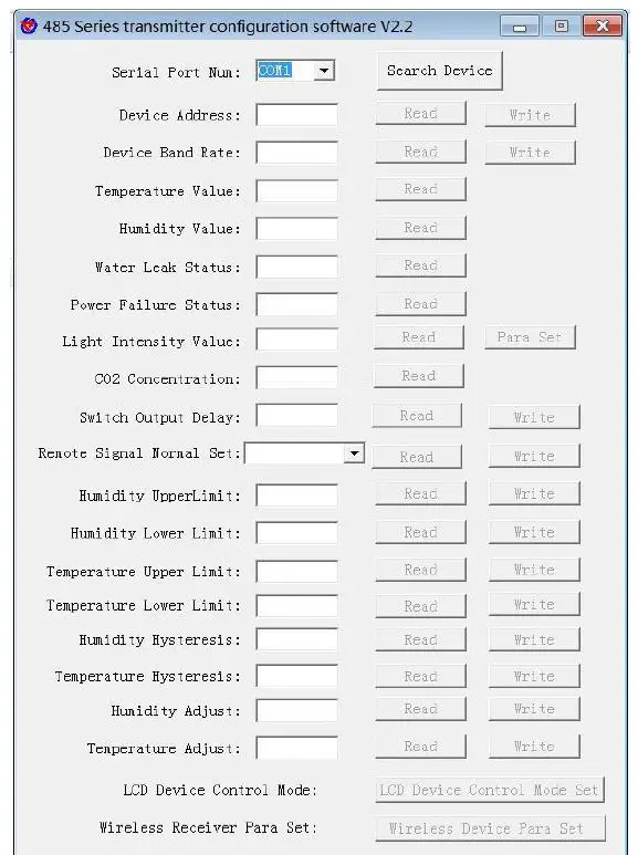
Open the data package, select “Debug software” — “485 parameter configuration software”, find “485 parameter configuration tool”
Just open it.
parameter settings
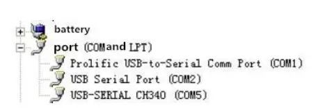
- select the correct COM port (“COM”-“Properties-Device Manager-Port” to view the COM port), the following figure lists the driver names of several different 485 converters.

- only connect one device and power on, click the test baud rate of the software, the software will test the current device baud rate and address, the default baud rate is 4800bit / s, the default address is 0x01.

- Modify the address and baud rate according to the needs of use, and at the same time,
you can query the current functional status of the device. - If the test is unsuccessful, please recheck the device wiring and 485 driver installations.
4. letter of agreement
Communication basic parameters
| Coding | 8-bit binary |
| Data bit | 8 |
| Parity bit | None |
| Stop bit | 1 |
| Error checking | CRC (Redundant Cyclic Code) |
| Baud rate | 2400bit / s, 4800bit / s, 9600 bit / s can be set, the factory default is 4800bit / s |
4.2 Data frame format definition
Using Modbus-RTU communication protocol, the format is as follows:
- Time for initial structure ≥ 4 bytes
- Address code = 1 byte
- Function code = 1 byte
- Data area = N bytes
- Error check = 16-bit CRC code
- End structure ≥ 4 bytes of time
- Address code: the address of the transmitter, which is unique in the communication network (default 0x01).
- Function code: the instruction function instruction issued by the host; this transmitter only uses the function code 0x03 (read register data).
- Data area: The data area is specific communication data, pay attention to the high byte of 16bits data first!
- CRC code: two-byte check code.
Host inquiry frame structure:
| address code | function code | Register start address | Register length | Check digit low | Check digit high |
| 1byte | 1byte | 2byte | 2byte | 1byte | 1byte |
Slave response frame structure:
| address code | function code | Effective bytes | Data area | Second data area | Nth data area | Check code |
| 1byte | 1byte | 1byte | 2byte | 2byte | 2byte | 2byte |
4.3 Register address
| Register address | PLC or configuration address | content | operating |
| 0000 H | 40001 | humidity | Read only |
| 0001 H | 40002 | temperature | Read only |
| 0002 H | 40003 | Illuminance | Read only |
| 0003 H | 40004 | (Only enabled in | |
| 0~200000Lux, unit is | |||
| 1Lux) |
| 0006 H | 40007 | Illuminance (0~65535 unit 1Lux 0~200000 unit hundred Lux) | Read only |
Communication protocol example and explanation
Read the temperature and humidity value of device address 0x01
Inquiry frame
| address code | function code | Starting address | Data length | Check digit low | Check digit high |
| 0x01 | 0x03 | 0x00 0x00 | 0x00 0x02 | 0xC4 | 0x0B |
Response frame (for example, read temperature is -10.1 ℃, humidity is 65.8% RH)
| address code | function code | Effective bytes | Humidity value | Temperature value | Check digit low | Check digit high |
| 0x01 | 0x03 | 0x04 | 0x02 0x92 | 0xFF 0x9B | 0x5A | 0x3D |
Temperature: When the temperature is lower than 0 ℃, upload in the form of complement FF9B H (Hexadecimal) = -101 => Temperature = -10.1 ℃
humidity: 292 H (hex) = 658 => humidity = 65.8% RH
Read the illuminance value at device address 0x01
(0 ~ 65535 is read in units of 1 Lux or 0 ~ 200000 is read in units of 100 Lux)
Inquiry frame
| address code | function code | starting address | Data length | Check digit low | Check digit high |
| 0x01 | 0x03 | 0x00 0x06 | 0x00 0x01 | 0x64 | 0x0B |
Acknowledge frame (for example, read the illuminance of 30000 Lux)
| address code | function code | Returns the numb er of valid bytes | Data area | Check digit low | Check digit high |
| 0x01 | 0x03 | 0x02 | 0x05 0x30 | 0xBB | 0x00 |
Illumination calculation instructions:
- The product is a 0~65535 range transmitter, the unit is 1Lux 0530 H (hexadecimal) = 1328 => illuminance = 1328 Lux
- The product is a 0~200000 range transmitter, the unit is 100 Lux
0530 H (hexadecimal) = 1328 => illuminance = 132800 Lux
Read the illuminance value of the device address 0x01 (0 ~ 200000 is read in units of 1 Lux)
Inquiry frame
| address code | function cod e | starting address | Data length | Check digit lo w | Check digit hi gh |
| 0x01 | 0x03 | 0x00 0x02 | 0x00 0x02 | 0x65 | 0xCB |
Acknowledge frame (for example, read the illumination of 200,000 Lux)
| address c ode | function co de | Effective byte s | High illumin ation | Low illumin ation | Check digit low | Check digit high |
| 0x01 | 0x03 | 0x04 | 0x00 0x03 | 0x0D 0x40 | 0x0F | 0x53 |
Illumination calculation instructions:
This protocol is only used under 0 ~ 200000Lux range transmitter, the unit is 1Lux
30D40 H (Hexadecimal) = 200000 => Illumination = 200000 Lux
Read the temperature, humidity and illuminance value of the device address 0x01 (0~65535 are read in units of 1Lux)
Inquiry frame
| address code | function code | starting address | Data length | Check digit low | Check digit high |
| 0x01 | 0x03 | 0x00 0x00 | 0x00 0x07 | 0x04 | 0x08 |
Reply frame
| addre ss code | functio n code | Numb er of bytes | Humidi ty value | Temperatu re value | 000 2 | 000 3 | 000 4 | 000 5 | illu min atio n | Che ck cod e low bit | High bit of chec k code |
| 0x01 | 0x03 | 0x0E | 0x01 0x7E | 0x00 0xE7 | Inv alid data | Inv alid data | Inv alid data | Inv alid data | 0x8 5 0x1 F | 0xB 3 | 0X4 D |
humidity
17E H (hexadecimal) = 382 => humidity = 38.2%RH
temperature
0E7 H(hexadecimal)=231=> temperature = 23.1℃
illumination
851F H(Hexadecimal)=34079=> Illumination=34079Lux (0~200000 is read in units of 1Lux and hundreds of Lux)
Interrogation frame
| address code | unction code | initial address | Data length | Check code low bit | High bit of check code |
| 0x01 | 0x03 | 0x00 0x00 | 0x00 0x07 | 0x04 | 0x08 |
Reply frame
| addre ss code | functi on code | Num ber of bytes | Humid ity value | Tempera ture value | Hi gh lig ht | Lo w lig ht | 0004 | 0005 | illuminat ion Hundred Lux | Che ck code low bit | Hig h bit of che ck cod e |
| 0x01 | 0x03 | 0x0E | 0x01 0x7E | 0x00 0xE7 | 0x 00 0x 00 | 0x8 5 0x1 F | Inval id data | Inval id data | 0x01 0x54 | 0x2 D | 0x2 C |
humidity
017E H (hexadecimal) = 382 => humidity = 38.2%RH
temperature
00E7 H(hexadecimal)=231=> temperature = 23.1℃
illumination
0000 851F H(Hexadecimal)=34079 => Illumination =34079Lux
Light (100 Lux)
0154H (hexadecimal) = 340 => light = 340 hundred Lux = 34000 Lux
Read the temperature, humidity and illuminance value of device address 0x01(0 ~ 200000 is read in 1 Lux unit)
| address code | function code | starting address | Data length | Check digit lo w | Check digit hi gh |
| 0x01 | 0x03 | 0x00 0x00 | 0x00 0x04 | 0x44 | 0x09 |
Reply frame
| address code | function code | Bytes | Humidity value | Temperatur e value | High light | Low light | Check cod e |
| 0x01 | 0x03 | 0x08 | 0x02 0x92 | 0x80 0x65 | 0x00 0x03 | 0x0D 0x40 | 0x01 0x6F |
Common problems and solutions
Device cannot be connected to PLC or computer
possible reason:
- The computer has multiple COM ports, and the selected port is incorrect.
- The device address is wrong, or there are devices with duplicate addresses (the factory default is all 1).
- Baud rate, check mode, data bit, stop bit error.
- The host’s polling interval and waiting time for answering are too short, and both need to be set above 200ms.
- The 485 bus is disconnected, or the A and B lines are reversed.
- If the number of devices is too large or the wiring is too long, power should be supplied nearby, and a 485 booster should be added, and 120Ω terminal resistance should be added at the same time.
- The USB to 485 driver is not installed or damaged.
- The equipment is damaged.
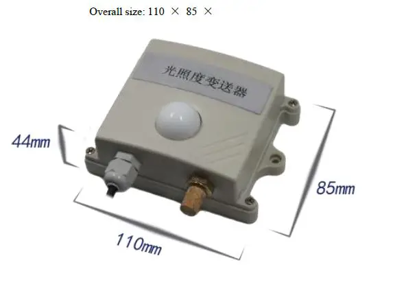
Appendix: Shell dimensions