ICM CONTROLS ICM401A Phase Loss and Reversal Protection Instruction Manual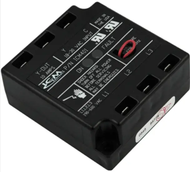
MODE OF OPERATION
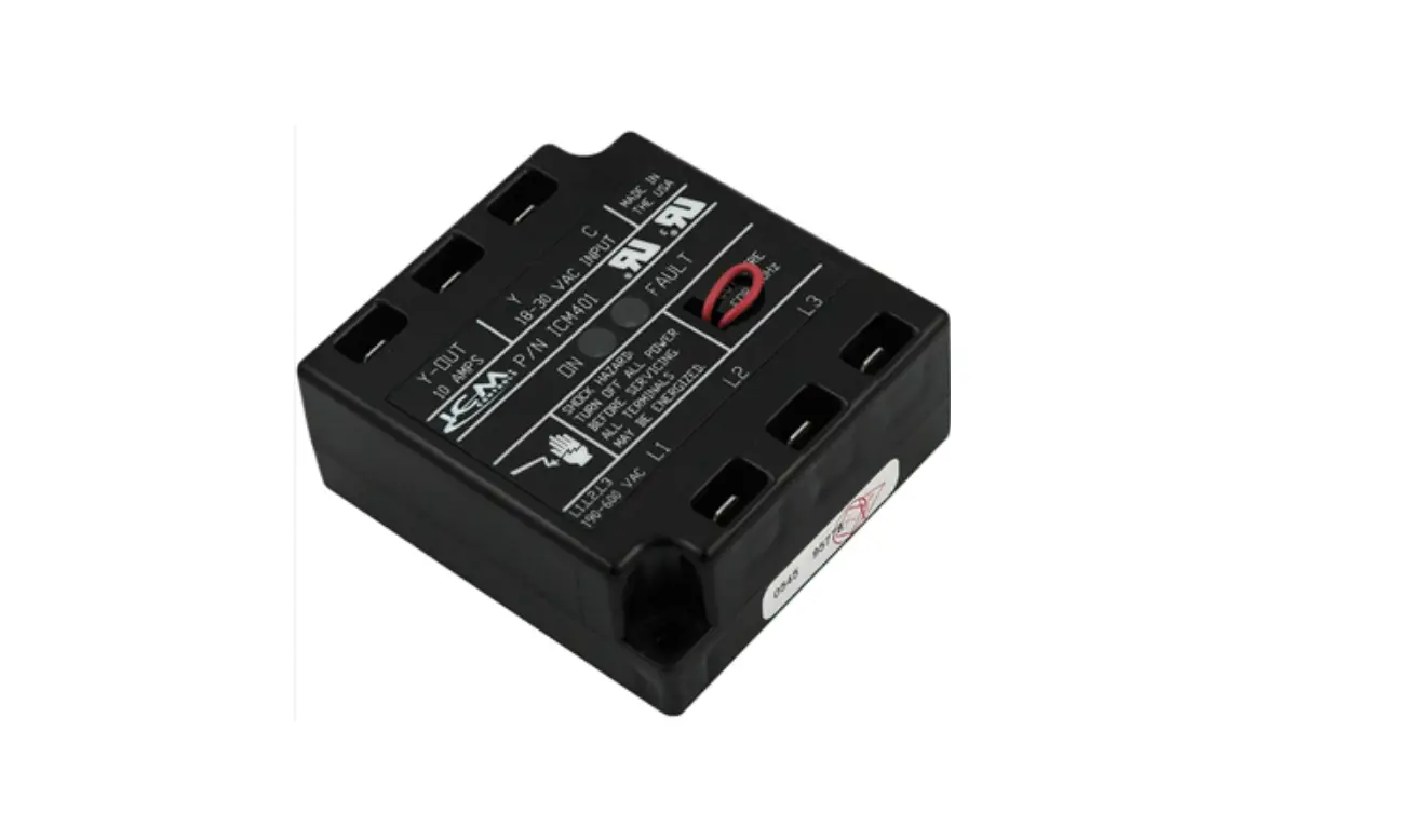
Upon wiring three phase voltage (180-600 VAC) to the ICM401A and connecting 24 VAC singlephase voltage to the Y & C terminals, the control will continuously monitor the three-phase line for phase loss and phase reversal. If all voltage conditions are within the specified range, a green light will illuminate on the ICM401A, and the Y-OUT terminal will be energized with 24 VAC. Upon a phase loss or a phase reversal, a red fault light will illuminate on the ICM401A
indicating a fault is presently occurring and the Y-OUT terminal will be de-energized. Once the fault is no longer present and providing the 24 VAC control voltage is still applied at Y & C, the ICM401A will automatically re-energize the Y-OUT terminal.
SPECIFICATIONS
- Input
- Voltage: 180-600 VAC
- Frequency: 50-60 Hz
– Jumper Wire Cut: 50 Hz - Control Voltage: 18-32 VAC
Output - Ratings:
– Type: Relay
– Form: SPST
– N.O.: 6 amps @ 32 VAC max
TROUBLESHOOTING
| Red Status Ligh | Green Status Ligh | Output (Y-Out) | Operational Status or Fault Condition |
| OFF | ON | ON | Normal operation and voltage conditions are within the specified range. |
| ON | OFF | OFF | Phase loss or phase reversal detected. Check phase -phase voltages A-B, B-C, A-C. |
| OFF | OFF | OFF | 24 VAC control voltage is not present |
For any questions with installation or operation, please call our technical support
hotline at 1-800-365-5525.
CAUTION
- High Voltage Shock hazard!
- Disconnect all power to the system before making any connections.
- Failure to adhere to all safety standards and personal protection when working with high voltage can result in personal injury or death.
- Installation of the ICM401A should be performed by trained technicians only. Adhere to all local and national electric codes.
INSTALLATION
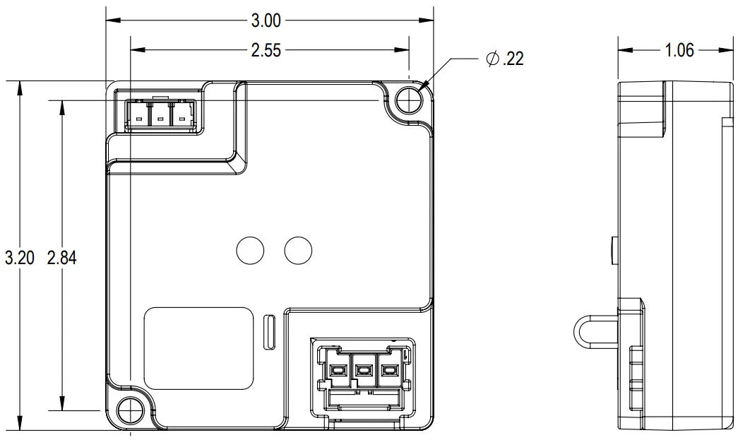
- Using (2) #8 screws mount the ICM401A in a cool, dry, easily accessible location in the control panel. Torque screws to 10 + 2in-lb per screw.
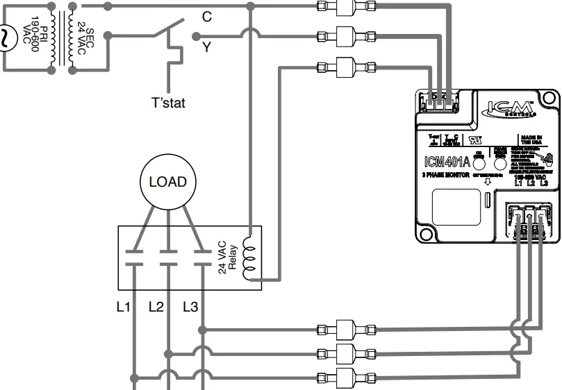
- Connect the line side harness of the ICM401A in parallel with the line side of the contactor as shown in figure 1 using the appropriate mating connectors.
- Connect the low voltage harnesses to the 24 VAC source and contactor coil as shown in figure 1 using the appropriate mating connectors.
DIMENSIONAL DIAGRAM
WIRING DIAGRAM (Fig. 1)