![]() X1 Series User Manual
X1 Series User Manual
6.0kw – 8.0kw
X1 Series 6.0kw – 8.0kw
Copyright Declaration
The copyright of this manual belongs to SolaX Power Network Technology(Zhe jiang) Co., Ltd.. Any corporation or individual should not plagiarize, partially or fully copy (including software,etc.), and no reproduction or distribution of it in any form or by any means. All rights reserved. SolaX Power Network Technology (Zhe jiang) Co.,Ltd. . reserves the right of final interpretation.
Notes on this Manual
1.1 Scope of Validity
This manual is an integral part of X1 Series, it describes the assembly, installation, commissioning, maintenance and failure of the product. Please read it carefully before operating.
| X1-6.0-T-D | X1-7.0-T-D | X1-8.0-T-D |
| X1-6.0-T-N | X1-7.0-T-N | X1-8.0-T-N |
Note:
“6.0” means 6.0kW.
”T” means “double” MPPT strings.
“D” means with “DC Switch”.
”N” means without “DC Switch”.
Keep this manual at where is accessible all the time.
1.2 Target Group
This manual is for qualified electricians. The tasks described in this manual only can be performed by qualified electricians.
1.3 Symbols Used
The following types of safety instructions and general information appear in this document as described below:
![]() Danger!
Danger!
“Danger” indicates a hazardous situation which, if not avoided, will result in death or serious injury.![]() Warning!
Warning!
“Warning” indicates a hazardous situation which, if not avoided, could result in death or serious injury.![]() Caution!
Caution!
“Caution” indicates a hazardous situation which, if not avoided, could result in minor or moderate injury.![]() Note!
Note!
“Note” provides tips that are valuable for the optimal operation of your product.
Safety
2.1 Appropriate Usage
The X1 Series are PV inverters which can convert the DC current of the PV generator into AC current and feed it into the public grid.
![]()
►Surge protection devices (SPDs) for PV installation![]() Warning!
Warning!
Over-voltage protection with surge arresters should be provided when the PV power system is installed.
The grid connected inverter is fitted with SPDs in both PV input side and MAINS side.
Lightning will cause a damage either from a direct strike or from surges due to a nearby strike.
Induced surges are the most likely cause of lightning damage in majority or installations, especially in rural areas where electricity is usually provided by long overhead lines.
Surge may be included on both the PV array conduction and the AC cables leading to the building.
Specialists in lightning protection should be consulted during the end use application.
Using appropriate external lightning protection, the effect of a direct lightning strike into a building can be mitigated in a controlled way, and the lightning current can be discharged into the ground.
Installation of SPDs to protect the inverter against mechanical damage and excessive stress include a surge arrester in case of a building with external lightning protection system (LPS) when separation distance is kept.
To protect the DC system, surge suppression device (SPD type2) should be fitted at the inverter end of the DC cabling and at the array located between the inverter and the PV generator, if the voltage protection level (VP) of the surge arresters is greater than 1100V, an additional SPD type 3 required for surge protection for electrical devices.
To protect the AC system, surge suppression devices (SPD type2) should be fitted at the main incoming point of AC supply (at the consumer’s cutout), located between the inverter and the meter/distribution system; SPD (test impulse D1) for signal line according to EN 61632-1.
All DC cables should be installed to provide as short a run as possible, and positive and negative cables of the string or main DC supply should be bundled together. Avoiding the creation of loops in the system. This requirement for short runs and bundling includes any associated earth bundling conductors.
Spark gap devices are not suitable to be used in DC circuits once conducting, they won’t stop conducting until the voltage across their terminals is typically below 30 volts.
►Anti-Islanding effect
Islanding effect is a special phenomenon that grid-connected PV system still supply power to the nearby grid when the voltage loss is happened in the power system. It is dangerous for maintenance personnel and the public.
X1 series provide Active Frequency Drift(AFD) to prevent islanding effect.
2.2 Important Safety Instructions
![]() Danger!
Danger!
Danger to life due to high voltages in the inverter!
- All work must be carried out by qualified electrician.
- The appliance is not to be used by children or persons with reduced physical sensory or mental capabilities, or lack of experience and knowledge, unless they have been given supervision or instruction.
- Children should be supervised to ensure that they do not play with the appliance.
![]() Caution!
Caution!
Danger of burn injuries due to hot enclosure parts!
- During operation, the upper lid of the enclosure and the enclosure body may become hot.
- Only touch the lower enclosure lid during operation.
![]() Caution!
Caution!
Possible damage to health as a result of the effects of radiation!
- Do not stay closer than 20 cm to inverter for any length of time.
![]() Note!
Note!
Grounding the PV generator.
- Comply with the local requirements for grounding the PV modules and the PV generator. SolaX recommends connecting the generator frame and other electrically conductive surfaces in a manner which ensures continuous conduction and ground these in order to have optimal protection of system and persons.
![]() Warning!
Warning!
- Ensure input DC voltage ≤Max. DC voltage ≤ Over voltage may cause permanent damage to inverter or other losses, which will not be included in warranty!
![]() Warning!
Warning!
- Authorized service personnel must disconnect both AC and DC power from X1 series before attempting any maintenance or cleaning or working on any circuits connected to the X1 series.
![]() Warning!
Warning!
Do not operate the inverter when the device is running.![]() Warning!
Warning!
Risk of electric shock!
- Prior to the application, please read this section carefully to ensure correct and safe application. Please keep the user manual properly.
- Use only attachments recommended or sold by SolaX. Otherwise may result in a risk of fire, electric shock, or injury to person.
- Make sure that existing wiring is in good condition and that wire is notundersized.
- Do not disassemble any parts of inverter which are not mentioned in installation guide. It contains no user-serviceable parts. See Warranty for instructions on obtaining service. Attempting to service the X1 Series inverter yourself may result in a risk of electric shock or fire and will void your warranty.
- Keep away from flammable, explosive materials to avoid fire disaster. The installation place should be away from humid or corrosive substance. Authorized service personnel must use insulated tools when installing or working with this equipment.
- PV modules shall have an IEC 61730 class A rating.
- Never touch either the positive or negative pole of PV connecting device.
Strictly prohibit touching both of them at the same time. - The unit contains capacitors that remain charged to a potentially lethal voltage after the MAINS and PV supply has been disconnected.
- Hazardous voltage will present for up to 5 minutes after disconnection from power supply.
CAUTION-RISK of electric shock from energy stored in capacitor,. Never operate on the solar inverter couplers, The MAINS cables, PV cables or the PV generator when power is applied. After switching off the PV and Mains, always wait for 5minutes to let the intermediate circuit capacitors discharge before you unplug DC and MAINS couplers. - When accessing the internal circuit of solar inverter, it is very important to wait 5minutes before operating the power circuit or demounting the electrolyte capacitors inside the device. Do not open the device before hand since the capacitors require time to sufficiently discharge!
- Measure the voltage between terminals UDC+ and UDC- with a multi-meter (impedance at least 1Mohm) to ensure that the device is discharged before beginning work (35VDC) inside the device.
PE Connection and Leakage Current
- All inverters incorporate a certified internal Residual Current Device(RCD) in order to protect against possible electrocution and fire hazard in case of a malfunction in the PV array, cables or inverter.There are 2 trip thresholds for the RCD as required for certification (IEC 62109-2:2011). The default value for electrocution protection is 30mA,and for slow rising current is 300mA.
- If an external RCD is required by local regulations, check which type of RCD is required for relevant eletric code. It recommends using a type-A RCD. The recommended RCD values is 100mA or 300mA unless a lower value is required by the specific local electric codes. When required by local regulations, the use an RCD type B is permitted.
The device is intended to connect to a PV generator with a capacitance limit of approx. 700nf. Warning!
High leakage current!
Earth connection essential before connecting supply.
- Incorrect grounding can cause physical injury, death or equipment malfunction and increase electromagnetic.
- Make sure that grounding conductor is adequately sized as required by safety regulations.
- Do not connect the ground terminals of the unit in series in case of a multiple installation. This product can cause current with a d.c component, Where a residual current operated protective (RCD) or monitoring (RCM) device is used for protection in case of direct or indirect contact, only an RCD or RCM of type B is allowed on the supply side of this product.
- For United Kingdom
- The installation that connects the equipment to the supply terminals shall comply with the requirements of BS 7671.
- Electrical installation of PV system shall comply with requirements of BS 7671 and IEC 60364-7-712.
- No protection settings can be altered.
- Installer shall ensure that equipment is so installed and operated to maintain at all times compliance with the requirements of ESQCR22(1)(a). For Australia and New Zealand
- lectical installation and maintenance shall be conducted by licensed electrician and shall comply with Australia National Wiring Rules.
2.3 Explanation of Symbols
This section gives an explanation of all the symbols shown on the inverter and on the type label.
Symbols on the Inverter
| Symbol | Explanation |
| Operating Display. | |
| Communication is active. | |
| An error has occurred, please inform your installer immediately. |
Symbols on the Type Label
| Symbol | Explanation |
 | CE mark. The inverter complies with the requirements of the applicable CE guidelines. |
| RCM remark. | |
| SAA certification. | |
 | Beware of hot surface. The inverter can become hot during operation. Avoid contact during operation. |
 | Danger of high voltages. Danger to life due to high voltages in the inverter! |
 | Danger. Risk of electric shock! |
 | Observe enclosed documentation. |
| The inverter can not be disposed together with the household waste. Disposal information can be found in the enclosed documentation. | |
| Do not operate this inverter until it is isolated from mains and on-site PV generation suppliers. | |
| Danger to life due to high voltage. There is residual voltage in the inverter which needs 5 min to discharge. • Wait 5 min before you open the upper lid or the DC lid. |
2.4 EC Directives
This chapter follows the requirements of the European low voltage directives, which contains the safety instructions and conditions of acceptability for the endues system, which you must follow when installing, operating and servicing the unit. If ignored, physical injury or death may follow, or damage may occur to the unit. Read this instructions before you work on the unit. If you are unable to understand the dangers, warnings, cautions or instructions, please contact an authorized service dealer before installing, operating and servicing the unit. The Grid connected inverter meets the requirement stipulated in Low Voltage Directive (LVD) 2014/35/EU and Electromagnetic Compatibility (EMC) Directive 2014/30/EU. The unit is based on:
EN 62109-1:2010 ; EN 62109-2:2011 ; IEC 62109-1(ed.1) ; IEC62109-2(ed.1) EN 61000-6-3:2007+A:2011 ; EN 61000-6-1:2007 ; EN 61000-6-2:2005 In case of installation in PV system, startup of the unit (i.e. start of designated operation) is prohibited until it is determined that the full system meets the requirements stipulated in EC Directive (2014/35/EU,2014/30/EU, etc.) The grid connected inverter leave the factory completely connecting device and ready for connection to the mains and PV supply ,the unit shall be installed in accordance with national wiring regulations. Compliance with safety regulations depends upon installing and configuring system correctly, including using the specified wires. The system must be installed only by professional assemblers who are familiar with requirements for safety and EMC. The assembler is responsible for ensuring that the end system complies with all the relevant laws in the country where it is to be used.
The individual subassembly of the system shall be interconnected by means of the wiring methods outlined in national/international such as the national electric code (NFPA) No.70 or VDE regulation 0107.
Introduction
3.1 Basic features
Thanks for your purchasing with SolaX X1 Series inverter. The X1 Series inverter is one of the finest inverters on the market today, incorporating state-of-the-art technology, high reliability, and convenient control features.
- Advanced DSP control technology.
- Utilize the latest high-efficiency power component.
- Optimal MPPT technology.
– Two independent MPP Tracking.
– Wide MPPT input range. - Advanced anti-islanding solutions.
- IP65 protection level.
- Max. efficiency up to 97.4%. EU efficiency up to 96.8%.
- THD<3%.
- Safety &Reliability: transformer less design with software and hardware protection.
- Export control.
- Power factor regulation.
- Friendly HMI.
– LED status indications.
– LCD display technical data, Human-machine interaction through press key.
– Dry contact communication interface.
– PC remote control.
– Upgrade through USB interface.
– Pocket Wi-Fi monitoring.
– Energy conservation.
Congratulations on your purchase of a X1-LX Series inverter from
3.2 Terminals of inverter
![]()
| Object | Description |
| A | DC Switch (optional) |
| B | DC Connector |
| C | AC Connector |
| D | RS 485/DRM(optional) /Meter(optional) |
| E | Waterproof Valve |
| F | USB for Upgrade |
| G | WIFI/LAN/GPRS |
| H | Grounding Screw |
![]() Warning!
Warning!
Only authorized personnel is allowed to set the connection
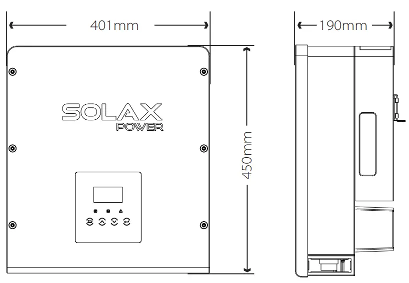
3.3 Dimension![]() Dimension
Dimension
Technical Data
4.1 DC input
| Model | X1-6.0-T-D/ X1-6.0-T-N | X1-7.0-T-D/X1-7.0-T-N | X1-8.0-T-D/X1-8.0-T-N |
| Max.PV array power[Wp] | 3000/4000 | 3000/5000 | 3000/6000 |
| Max. DC voltage[V] | 550 | ZZ | 550 |
| Nominal DC operating voltage[V] | 360 | 360 | 360 |
| MPPT voltage range [V] | 100-530 | 100-530 | 100-530 |
| MPPT voltage range[V](@full load) | 171-500 | 200-500 | 228-500 |
| Max. input current [A] | 24-Dec | 120 | 120 |
| Max. short circuit current [A] | 14/28 | 2 | 2 |
| Start operating voltage [V] | 120 | 14/28 | 14/28 |
| No. of MPP trackers | 2 | 24-Dec | 24-Dec |
| Strings per MPP tracker | 2-Jan | 2-Jan | 2-Jan |
| DC disconnection switch | optional | ||
4.2 AC output
| Model | X1-6.0-T-D/X1-6.0-T-N | X1-7.0-T-D/X1-7.0-T-N | X1-8.0-T-D/X1-8.0-T-N |
| Nominal apparent AC power[VA] | 6000 | 7000 | 8000/7700(220V) |
| Max.apparent AC power [VA] | 6600 | 7700 | 8800 |
| Nominal grid voltage[V] | 220/230/240 | ||
| Nominal grid Frequency/range[Hz] | 50;45-55/60;55-65 | ||
| Nominal AC current[A](@230V AC) | 26 | 30 | 34.7 |
| Max. AC current[A] | 28.7 | 33.5 | 38.3 |
| Max. inverter backed current to the array[mA] | 0 | ||
| THDi, rated power | <3% | ||
| Displacement power factor, adjustable | 0.8 leading…. 0.8 lagging | ||
| Feed in phase | single-phase | ||
4.3 Efficiency, Safety and Protection
| Model | X1-6.0-T-D/ X1-6.0-T-N | X1-7.0-T-D/ X1-7.0-T-N | X1-8.0-T-D/ X1-8.0-T-N |
| MPPT efficiency | 99.90% | 99.90% | 99.90% |
| Euro efficiency | 96.80% | 96.80% | 96.80% |
| Max. efficiency | 97.40% | 97.40% | 97.40% |
| Safety & Protection | |||
| Over/under voltage protection | YES | ||
| DC isolation protection | YES | ||
| Grid protection | YES | ||
| DC injection monitoring | YES | ||
| Back feed current monitoring | YES | ||
| Residual current detection | YES | ||
| Anti-islanding protection | YES | ||
| Over load protection | YES | ||
| Over heat protection | YES | ||
4.4 General Data
| Model | X1-6.0-T-D/ X1-6.0-T-N | X1-7.0-T-D/ X1-7.0-T-N | X1-8.0-T-D/ X1-8.0-T-N |
| Dimension [W/H/D](mm) | 450*401*190 | ||
| Dimension of packing [W/H/D](mm) | 560*492*305 | ||
| Net weight [kg] | 22 | ||
| Gross weight [kg] | 25 | ||
| Installation | Wall-mounted | ||
| Operating temperature range[℃] | -25~+60 (derating at 45) | ||
| Storage temperature [℃] | -25~+60 | ||
| Storage/Operation relative humidity | 0%~100%, non condensing | ||
| Max. operation altitude [m] | ≤2000 | ||
| Degree of protection | IP65 | ||
| Protection Class | Ⅰ | ||
| Self-consumption(night)[W] | <1 | ||
| Overvoltage Category | Ⅲ(MAINS),Ⅱ(PV) | ||
| Pollution Degree | Ⅱ | ||
| cooling concept | External: natural wind; Internal: intelligent fan | ||
| Tepical noise emission[dB] | <40 | ||
| Inverter Topology | Non-isolated | ||
| Communication interface | RS485/ Meter/CT(optional)/DRM,WIFI /GPRS/LAN/USB | ||
| Standard warranty [year] | Standard 5 years(10 years optional) | ||
Installation
5.1 Check for Transport Damage
Make sure the inverter is intact during transportation. If there are some visible damages, such as cracks, please contact your dealer immediately.
5.2 Packing List
Open the package and fetch out the product, check the accessories at first. The packing list shows as below.
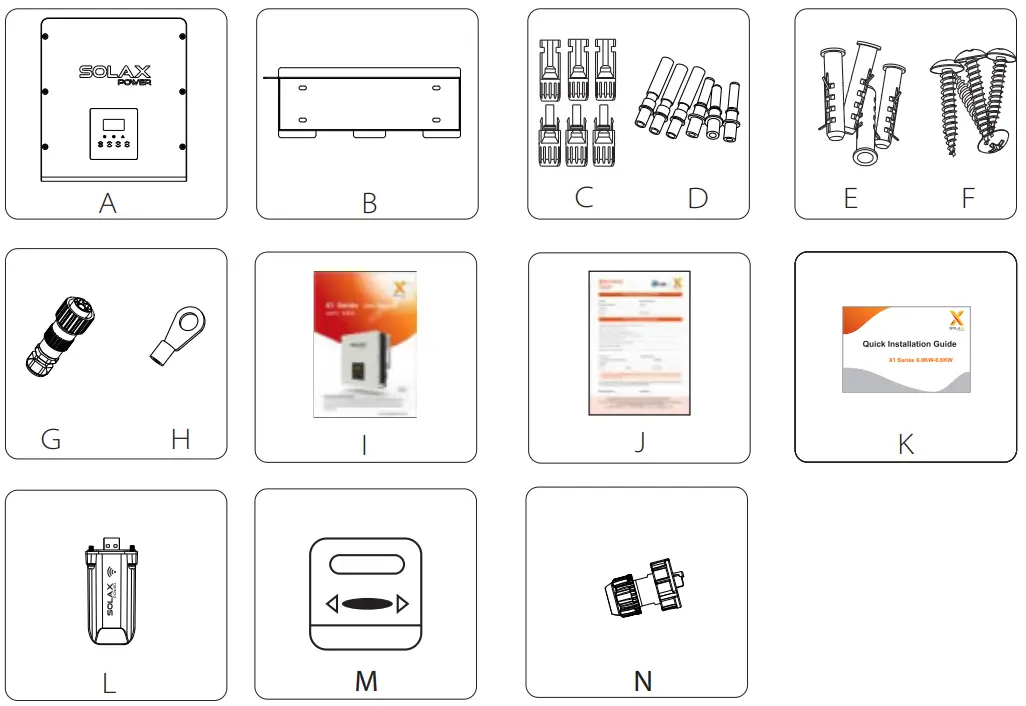
| Object | Quantity | Description |
| A | 1 | X1 series inverter |
| B | 1 | Bracket |
| C | 6 | DC connector |
| D | 6 | DC pin contact(3*positive, 3*negative) |
| E | 4 | Expansion tube |
| F | 4 | Expansion screw |
| G | 1 | AC connector |
| H | 1 | Earth terminal |
| I | 1 | Product manual |
| J | 1 | Warranty card |
| K | 1 | Quick installation guide |
| L | 1 | Pocket WiFi( Optional ) |
| M | 1 | Meter( Optional ) |
| N | 1 | Rj45 Plug |
5.3 Installation Precaution
X1 Series inverter is designed for outdoor installation (IP 65).
Make sure the installation site meets the following conditions:
- Not be exposed to glare.
- Not in areas where highly flammable materials are stored.
- Not in potential explosive areas.
- Not in the cool air directly.
- Not near the television antenna or antenna cable.
- Not higher than altitude of about 2000m above sea level.
- Not in environment of precipitation or humidity (>95%).
- Be sure the ventilation is good enough.
- The ambient temperature in the range of -25℃ to +60℃.
- The slope of the wall should be within ±5 °.
- The wall hanging the inverter should meet conditions below:
1.solid brick/concrete, or strength equivalent mounting surface;
2.Inverter must be supported or strengthened if the wall’s strength isn’t enough(such as wooden wall, the wall covered by thick layer of decoration)
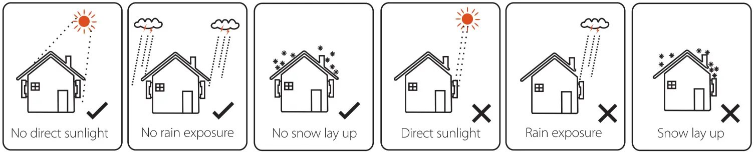
Please avoide direct sunlight, rain exposure, snow laying up during installing and operating.
![]() Available Space Size
Available Space Size
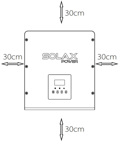
Table Available Space Size
| Position | Min.size |
| Left | 30cm |
| Right | 30cm |
| Top | 30cm |
| Bottom | 30cm |
| Front | 30cm |
5.4 Installation Steps![]() Preparation
Preparation
Below tools are needed before installation.
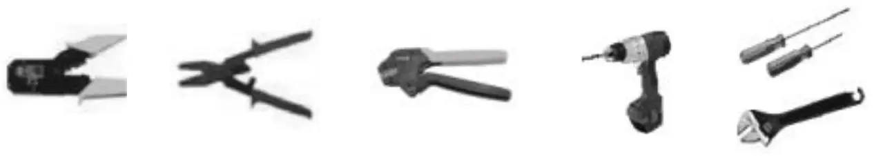
Installation tools : crimping pliers for binding post and RJ 45, screwdriver, stripping pliers,wire crimper manual wrench and φ10 drill.![]() Step 1: Screw the wall bracket on the wall
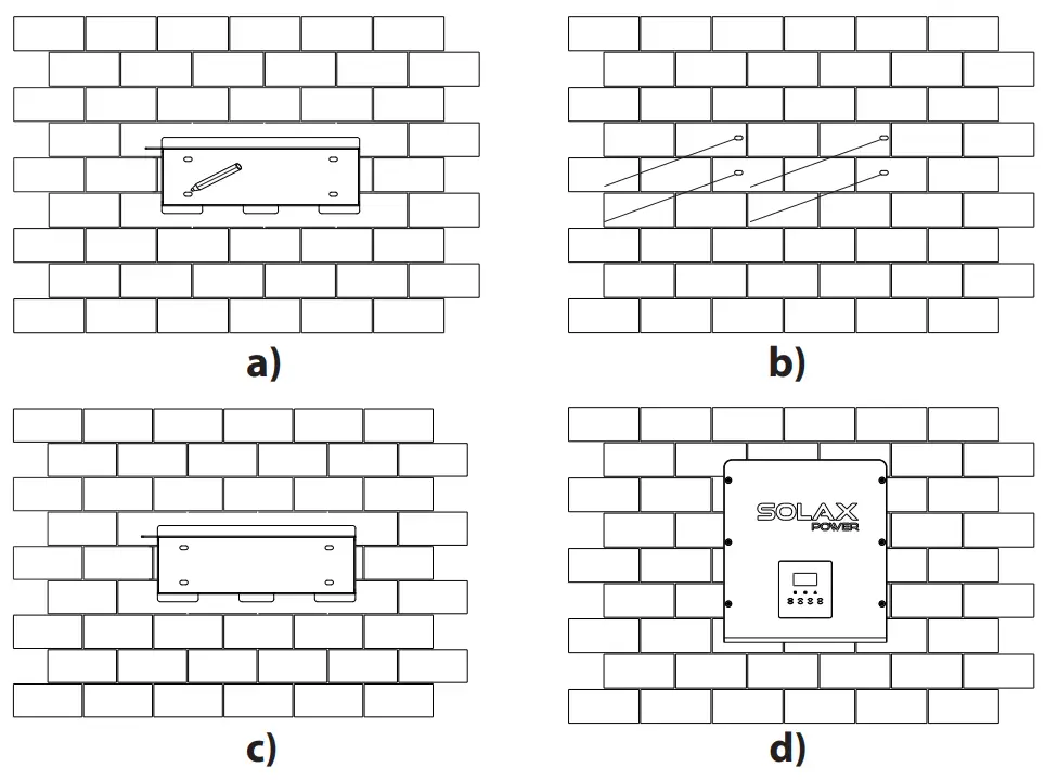
Step 1: Screw the wall bracket on the wall
a) Use the wall bracket as a template to mark the position of the 4 holes on the wall.
b) Drill holes with driller, make sure the holes are deep enough (at least 50mm) for installation, and then tighten the expansion tubes.
c) Install the expansion tubes in the holes, and tighten them. Then install the wall bracket by using the expansion screws.(torque: 12± 0.2Nm)![]() Step 2: Match the inverter with wall bracket
Step 2: Match the inverter with wall bracket
d) Hang the inverter over the bracket, move the inverter close to it, slightly lay down the inverter, and make sure the 4 mounting bars on the back are fixed well with the 4 grooves on the bracket.
5.5 Connection of the Inverter
5.5.1 The Main Steps to Connect to the Inverter
PV String Connection
X1series inverter have a couple of PV connectors which can be connected in series into 2-strings PV modules. Please select PV modules with excellent function and reliable quality. Open circuit voltage of module array connected should be < Max.DC (table as follow) input voltage, and operating voltage should be within the MPPT voltage range.
Table 3 Max. DC Voltage Limitation
| Model | X1-6.0-T-D/ X1-6.0-T-N | X1-7.0-T-D/ X1-7.0-T-N | X1-8.0-T-D/ X1-8.0-T-N |
| Max.DC Voltage | 550V | ||
![]() Danger!
Danger!
Danger to life due to high voltages on DC conductors.
when exposed to sunlight, the PV array generates dangerous DC voltage which is present in the DC conductors. Touching the DC conductors can lead to lethal electric shocks. Cover the PV modules.
Do not touch the DC conductors.![]() Note!
Note!
Please choose a suitable external DC switch if the model (X1-6.0T-N,X1-7.0-T-N,X1-8.0-T-N) is purchased.![]() Warning!
Warning!
PV module voltage is very high which belongs to dangerous voltage range, please comply with the electric safety rules when connecting.![]() Warning!
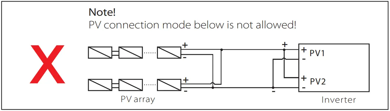
Warning!
Please do not make PV positive or negative ground!![]() Note!
Note!
Please follow the requirements of PV modules as below: Same type; Same quantity; Identical alignment; Identical tilt. In order to save cable and reduce the DC loss, we suggest installing the inverter near PV modules.
Connection Steps
Below tools are needed before connection.

a) Turn off the DC switch, then Choose 12 AWG wire to connect the PV module.
b) Trip 7mm of insulation from the wire end by using the strapping pliers.

c) Insert striped wire into pin contact and ensure all conductor strand are captured in the pin contact.
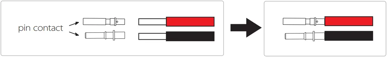
d) Crimp pin contact by using the wire crimper.
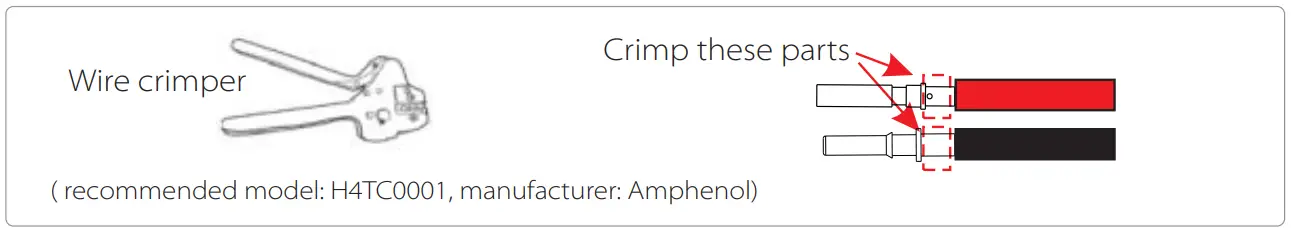
e) Separate the DC connector as two parts: the plug and the cable nut.
Then insert the wire with pin contact through the cable nut.
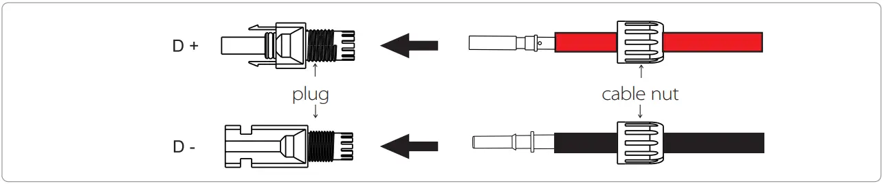
f ) Insert the wire into plug forcibly, when a “click” is heard or felt the pin contact assembly is seated correctly. Then tighten the cable nut.

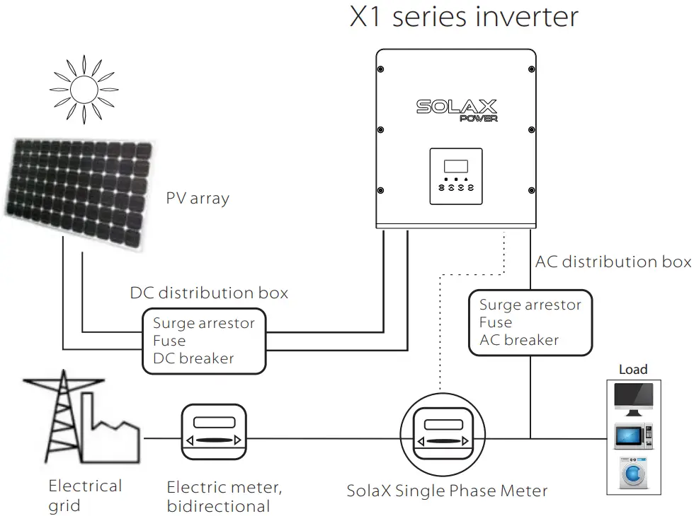
![]() Grid Connection
Grid Connection
X1 series inverter are designed for single phase grid. Voltage range is 220/230/240V, frequency is 50/60Hz. Other technical requests should comply with the requirement of the local public grid.
Table 4 Cable and Micro-breaker recommended
| Model | X1-6.0-T-D/X1-6.0-T-N | X1-7.0-T-D/X1-7.0-T-N | X1-8.0-T-D/X1-8.0-T-N |
| L,N Cable | 8-10mm² | 8-10mm² | 8-10mm² |
| PE Cable | 4-10mm² | 4-10mm² | 4-10mm² |
| Micro-breaker | 50A | 50A | 50A |
*The parameters have some differences because of different environment and material. Please according to the local conditions to choose appropriate cable and micro-breaker.
Micro-breaker should be installed between inverter and grid, any loads should not be connected with inverter directly.
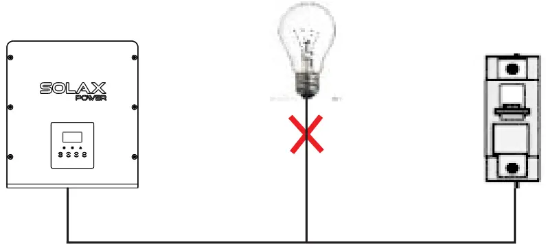 Incorrect Connection between Load and Inverter
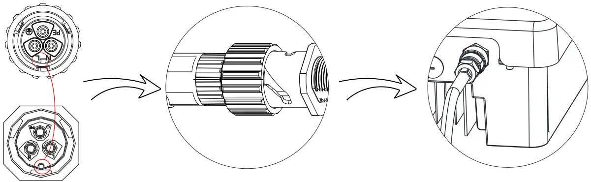
Connection Steps
a) Check the grid voltage and compare with the permissive voltage range (refer to technical data).
b) Disconnect the circuit-breaker from all the phases and secure against reconnection.
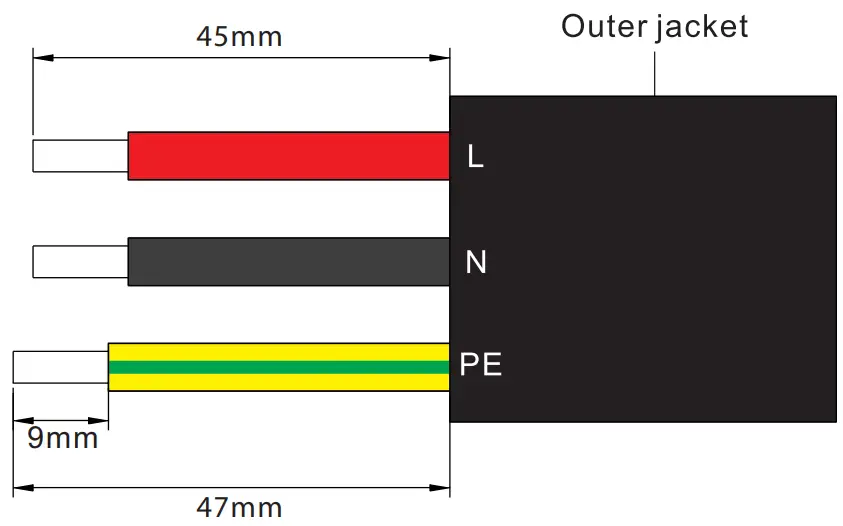
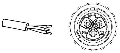
c) Trip the wires(Choose 8 AWG wire): –
Trip all the wires to 45mm and the PE wire to 47mm.
– Use the crimping pliers to trip 9mm of insulation from Al wire ends as below.
d) Separate the AC plug into three parts as below.
– Hold the middle part of the female insert, rotate the back shell to loose it, and detach it from female inset.
– Remove the cable nut (with rubber insert) from the back shell.
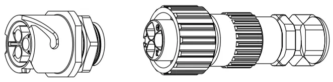
e) Slide the cable nut and then back shell onto the cable.
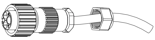
f ) Insert the tripped end of each three wires into the appropriate hole in the female insert, and then tight each screw (to tight each wire in place).(hexagon wrench .torque:0.8±0.1Nm))
g) Tighten the threaded sleeve.
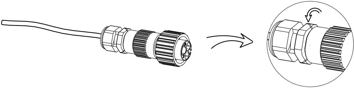
h) Screw down the pressure screw.(torque:3±0.3Nm)
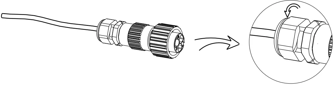
I) Align the groove of male terminal with the convex of female terminal , then tighten the bush in male terminal
Selection of Fuses and Cables
Main cable(AC line cable)shall be short circuit protected and thermal overload protected.
Always fit the input cable with fuse. Normal gG(US:CC or T)fuses will protect the input cable in short circuit situation. They will also prevent damage to adjoining equipment.
Dimension the fuses according to local safety regulations, appropriate input voltage and the related current of the solar inverter.
AC output protected by external fuse(gG rated current 28A/250VAC for 6.0KW ;
32A/250VAC for 7KW;35A/250VAC for 8KW)provides in all live connections to the AC supply.
The rated short circuit breaking capacity of the above protective device shall be at least equal to the prospective fault current at the point of installation. See section technical data of this manual details.
AC output cable: Cu; L, N+PE: 2*5.0mm²+5.0mm² for 6.0KW , 2*5mm²+5mm² for 7KWand 2*8mm²+8mm² for 8KW @40℃ ambient temperature with a max length of 5m, with operating time of the fuses is less than 5 seconds, installation method B2 according to EN60204-1:2006, annex D: cable in conduit cable trucking system,
number of loaded circuit only one. Use H07RNF(cord designation 60245 IEC66) for an ambient temperature of 40℃ or less and use 90℃ wire for ambient temperature between 40℃ and 60℃.
Note 1: For those different conditions mentioned above, dimension of the cables according to local safety regulations, appropriate input voltage and the load and the load current of the unit.(You can choose a thicker cable but the fuses must rated according to the cable.)
Note 2: Fuses must be approved by Notified Body.
Inverter is not provided galvanic isolation from the mains to the PV array, feedback current to the array is 0A/250VAC for 6.0KW /7.0KW/8.0KW,based on the fuse provided in the mains. Also in the worst case the reverse current comprises the sum of the short-circuit currents of all intact lines.
Therefore the current-carrying capacity of the components and sub-assemblies provided in the end-use system(connectors, cables, junction box, switch ger, etc.) and the reverse current PV modules shall be considered based on the feedback current and reverse current. The direct current(DC) circuit breaker or fuse between each solar generator and inverter shall be provided based on solar inverter input ratings.
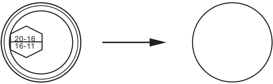
Select DC cables based in the above inverter back-feed current and ISC PV rating and Vmax ratings.![]() Note!
Note!
If the AC cable you choose is 16mn2or larger, you need to break the connection between the two rubber rings which make up the rubber insert as below.
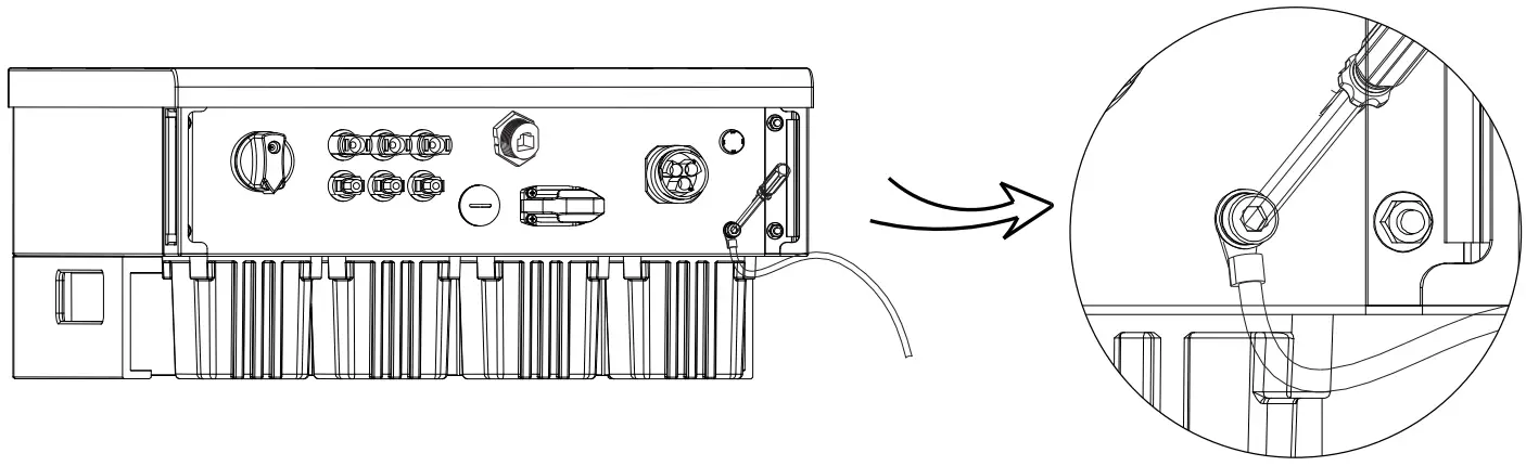
![]() Earth Connection
Earth Connection
Screw the ground screw with Allen wrench shown as follow. (4 hexagon wrench.torque:1.5±0.2Nm)
5.5.2 Communication interface
This product has a series of communication interfaces: such as WIFI, RS485/Meter, DRM and USB for upgrading for human and machine communication. Operating information like output voltage, current, frequency, faulty information, etc., can be delivered to PC or other monitoring equipment via these interfaces.
1. Wi-Fi(optional)
This inverter provides a Wi-Fi port which can collect information from inverter including status, performance and updating information to monitoring website via connecting Pocket Wi-Fi( purchase the product from supplier if needed)
Connection steps:
- Plug the Pocket Wi-Fi into “Wi-Fi” port at the bottom of inverter.
- Connect the WIFI with router.
- Set the station account on the solaX web.(Please check the Pocket Wi-Fi user manual for more details) (torque:0.6±0.1Nm)
2. RS 485/Meter/DRM
a. RS 485
RS 485 is one standard communication interface which can transmit the real data from inverter to PC or other monitoring equipment’s.
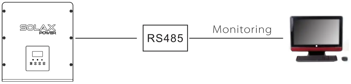
![]() RS 485 Connection Steps:
RS 485 Connection Steps:
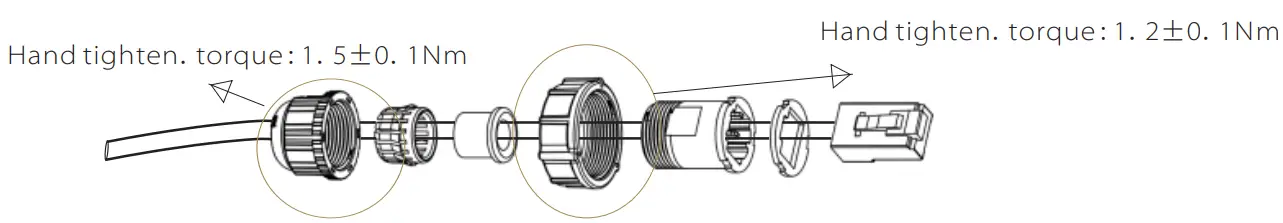
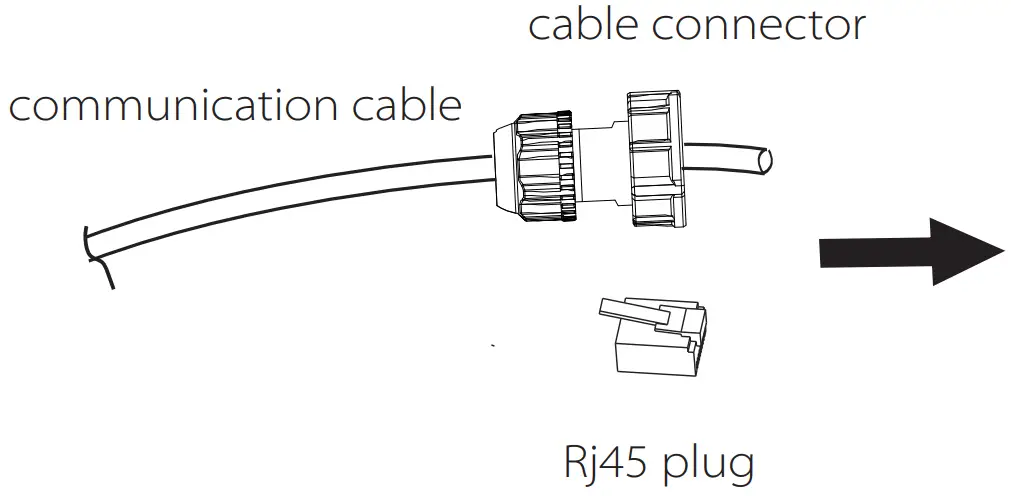
- Prepare RJ45 connector and a communication cable.
- Trip the insulation from the communication cable.
- Let the communication cable pass though the waterproof connector with RJ45, then insert it into the RJ45 connector following the PIN definition rule.

- Crimp the RJ45 connector with the crimping plier.
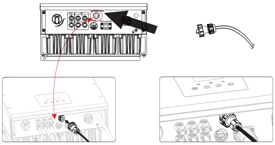
- Insert the cable into the RS 485/Meter port of the inverter, and tighten the waterproof connector.
b. Meter (optional)
A meter can communicate with the X1 series inverter through this interface, then you can:
- Monitor the energy to grid and from grid throughout the whole day.
- Achieve the export control function with a higher accuracy.
![]() Meter Connection Steps:
Meter Connection Steps:
Please see the Quick Guide for single-Phase Meter Installation for details.
![]() Note!
Note!
It is necessary to connect meter to inverter otherwise inverter will shutdown with a “Meter fault” alert.
The smart meter must be authorized by Solax, any third party or non-authorized meter may not match with the inverter.
Solax will not take the responsibility if the meter is unavailable.
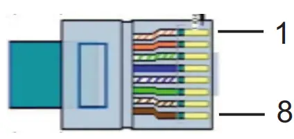
The PIN definitions of RS 485/meter interface are as below.
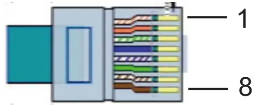
| PIN | 1 | 2 | 3 | 4 | 5 | 6 | 7 | 8 |
| Definition | X | X | X | 485_A/ Meter_A | 485_B/ Meter_B | X | X | X |
Step1. Prepare a communication cable (without sheath) and insert the com medication cable through the cable connector which can be found in the accessories package .
Step2. Crimp the communication cable with a Rj45 plug which is inside of the cable connector.
Step3. Insert the cable connector into COM port inside of inverter and screw it thightly. Then insert other side of communication cable into home router or other device.
Step1
Step3
c. DRM
DRM is provided to support several demand response modes by giving control signals as below.
| PIN | 1 | 2 | 3 | 4 | 5 | 6 | 7 | 8 |
| Definition | X | DRM0 | GND_COM | X | X | DRM1 | RefGen | X |
![]() Connection Steps:
Connection Steps:
- Prepare RJ45 connector and a communication cable.
- Trip the insulation from the communication cable.
- Let the communication cable pass though the waterproof plug, then insert it into the RJ45 connector following the PIN definition rule.
- Crimp the RJ45 connector with the crimping plier.
- Insert the cable into the DRM port of the inverter, and tighten the waterproof plug.
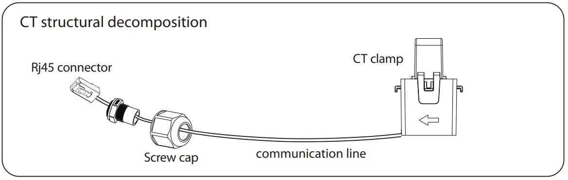
![]() CT Connection:
CT Connection:
The current sensor measures the current on the phase wire that runs between the inverter and the grid.
CT connection diagram
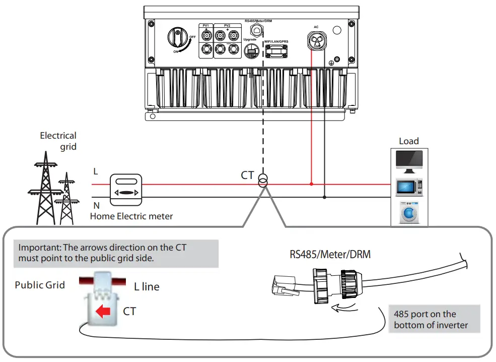
CT PIN Definition
When connecting the RJ45 connector with the wire of the CT, please follow the below sequence :
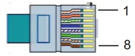
| PIN | 1 | 2 | 3 | 4 | 5 | 6 | 7 | 8 |
| Definition | CT+ | X | X | X | X | X | X | CT- |
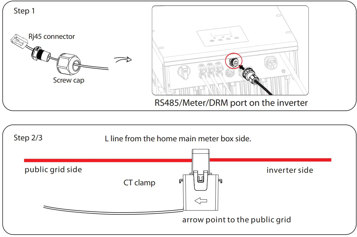
CT Connection Steps:![]() NOTE!
NOTE!
- Do not place the CT on the N Wire or the earth wire.
- Do not place the CT on the N and L wire simultaneously.
- Do not place the CT with the arrow pointing to the inverter side.
- Do not place the CT on the non-insulated wires.
- Do not use the wire over 25m.
- Insert the Rj45 connector of CT into the Meter port on the inverter, and screw down the screw cap tightly.
- Clip the CT clamp on L line from the home main meter box side.
- Make sure the current sensor is installed in the right direction: The arrow on the current sensor must point to the public grid.

Upgrade
User can update the inverter system through a U-disk.![]() Warning!
Warning!
Make sure the input voltage is more than 121V (in good illumination condition), or it may result in failing during updating.![]() Upgrade
Upgrade
1) Please contact our service support to get the update file, and extract it into your U-disk as the following file path:
ARM:
“update\ARM \618.00319.00_X1_SMART_ ARM _Vx.xx_xxxxxxxx.usb”;
DSP:
“update\DSP\618.00318.00_X1_SMART_DSP_Vx.xx_xxxxxxxx.usb”.
Note: Vx.xx is version number, xxxxxxxx is file completion date.![]() Warning!
Warning!
Make sure the directory is in accordance with above form strictly!
Do not modify the program file name ! Or it may cause the inverter not work anymore !
2) Make sure the DC switch is off and the AC is disconnected with grid.
Unscrew the waterproof lid of Upgrade port by straight screwdriver as below.
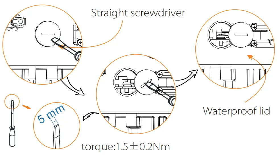
3) then insert U-disk into the USB port on the bottom of the inverter.
Then turn on DC switch or connect the PV connector, the LCD will show picture as below.
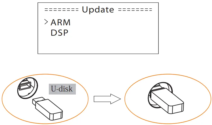
4) Press up and down to select the one that you want to update and press “OK” to confirm to update.
5) After the upgrade is complete, please remember to turn off the DC switch or disconnect the PV connector, then pull off the U-disk, screw the waterproof lid.![]() Warning!
Warning!
During updating, please don’t turn off the DC switch or disconnect the PV connector, then reinsert the U-disk if the updating is stopped.
4. Earth Fault Alarm(Optional)
The earth fault alarm is the additional detection, as required by AS 4777.2 and AS/NZS 5033, it will give an alarm once the earth impedance of the PV arrays is less than 30KΩ .
5.6 Run the inverter![]() Start inverter after checking all below steps:
Start inverter after checking all below steps:
a. Check that device is fixed well on the wall.
b. Make sure all the DC breakers and AC breakers are disconnected.
c. AC cable is connected to grid correctly.
d. All PV panels are connected to inverter correctly, DC connectors which are not used should be sealed by cover.
e. Turn on the external AC and DC connectors.
f. Turn on the DC switch to the “ON”position.![]() Start inverter
Start inverter
- Inverter will start automatically when PV panels generate enough energy.
- Check the status of LED indication and LCD screen, the LED indication should be blue and the LCD screen should display the main interface.
- If the LED indication is not blue, please check the below:
– All the connections are right.
– All the external disconnect switches are closed.
– The DC switch of the inverter is in the “ON” position.
![]() Below is the three different status when operating, which means inverter starting up successfully.
Below is the three different status when operating, which means inverter starting up successfully.
Waiting: Inverter is waiting to checking when DC input voltage from panels is greater than 100V(lowest start-up voltage) but less than 120V(lowest operating voltage).
Checking: Inverter will check DC input environment automatically when DC input voltage from the PV panels exceeds 120V and PV panels have enough energy to start inverter.
Normal: Inverter begins to operate normally with blue light on. Meanwhile feedback energy to grid, LCD displays present output power.
Enter the setting interface to follow the instructions when it is first time to start up.![]() Warning!
Warning!
Power to the unit must be turned on only after installation work has been completed. All electrical connections must be carried out by qualified personnel in accordance with legislation in force in the country concerned.![]() Note!
Note!
Please set the inverter if it is the first time to start up.
Above steps are for the regular start of the inverter. If it is the first time to start up the inverter, you need to setup the inverter.![]() Energy control!
Energy control!
Equipment only to be used for the purpose outlined by SolaX.
Operation Method
6.1 Control panel
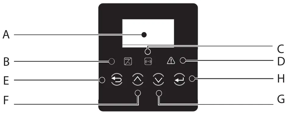
| Object | Name | Description |
| A | LCD Screen | Display the information of the inverter. |
| B | Indicator LED | Blue:The inverter is in normal state. |
| C | Yellow:The inverter is in communication. | |
| D | Red:The inverter is faulty. | |
| E | Function Button | ESC button: Return from current interface or function. |
| F | Up button: Move cursor to upside or increase value. | |
| G | Down button: Move cursor to downside or decrease value | |
| H | OK button: Confirm the selection. |
6.2 LCD Function
Please refer to the inverter for the most updated structure
Menu structure
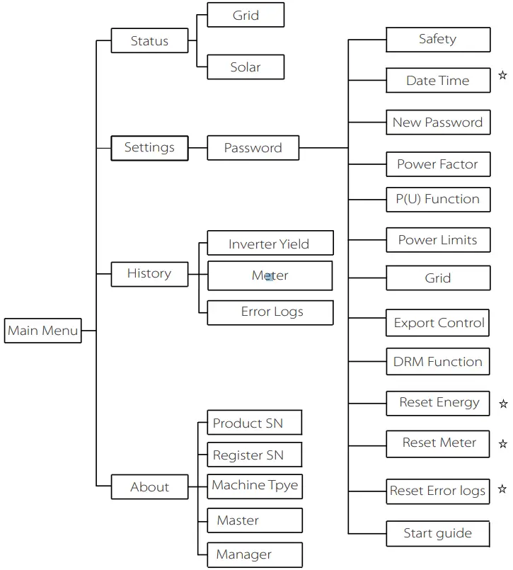 Note:
Note:
”⋇ ”Can be set by the end user.
Others can only be set by the technical or the installer with the installer password.
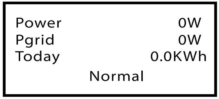
6.3 LCD Operation
- LCD Digital Display
The main interface is the default interface, the inverter will automatically jump to this interface when the system started up successfully or not operated for a period of time. The information of the interface is as below. “Power” means the timely output power; “Pgrid” means the power export to or import from the grid.“Today” means the power generated within the day. “Normal” shows the status of the inverter.
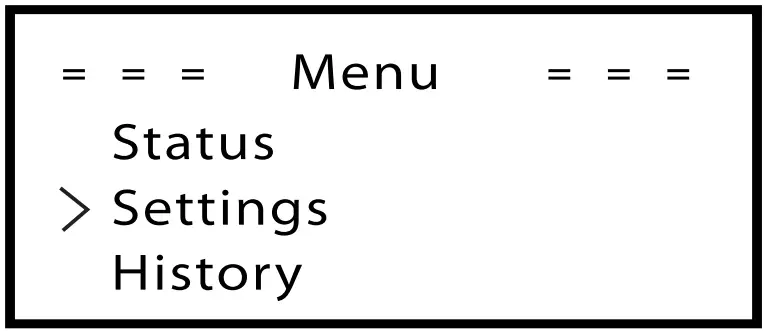
- Menu interface
The menu interface is a transfer interface for user to get into other interface to finish the setting or getting the information.
-User can get into this interface by pressing “OK” button when LCD displays the main interface.
-User can select interface by moving the cursor with function button, and press “OK” to confirm.
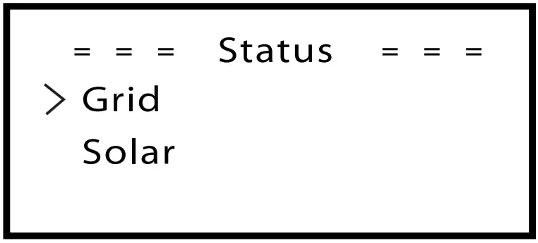
- Status
The status function contains two aspects of the inverter, grid and solar.
Press up and down to select and press “OK” to confirm the selection, press “ESC” to return to Menu.
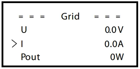
a) Grid
This status shows the current grid condition such as voltage, current, output power and the local consumed power. Pout measures the output of the inverter, Pgrid measures power export to or import from grid. Positive value means the energy feeds into grid, negative value means the energy used from the grid.
Press up and down button to review the parameter, press “ESC” to return to Status .
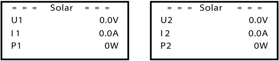
b) Solar
This status shows the real time PV condition of the system, such as input voltage, current and power situation of each PV input.
Press up and down button to review parameter, Press “ESC” to return to Status.
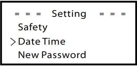
- Settings
Setting function is used for setting the inverter for time, connection, Grid and so on.
Since this function will change the inverter’s parameter, the end user with the user password as”0000” has the limited authority to change the setting. We need installer password to do most of the professional setting.
If inputting the installer password, the information of the LCD interface is as below.
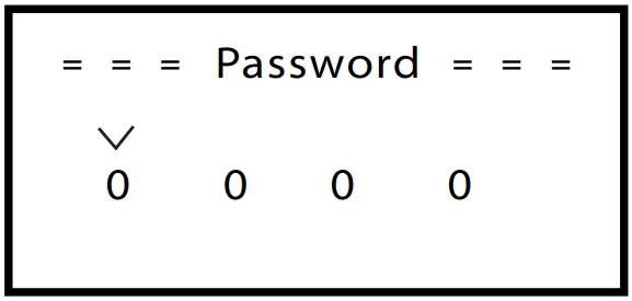
Password
The default password is “0000”for end user, which only allows the user to review the current setting and some easy setting. If professional change is needed, please contact with the distributor or factory for installer password. We need to increase or decrease the word by pressing up or down button. Press OK to confirm an alternate to the next word. After word is confirmed, press “OK” to enter password.
a) Safety
The user can set the safety standard here. According to different countries and grid tied standards. There is 2 standards for choice (May change without notice).
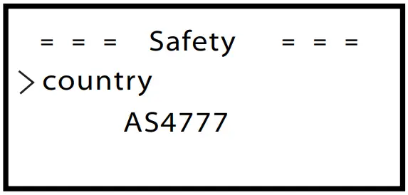
| Item | Standard | Country |
| 1 | AS 4777 | Australia |
| 2 | CQC | China |
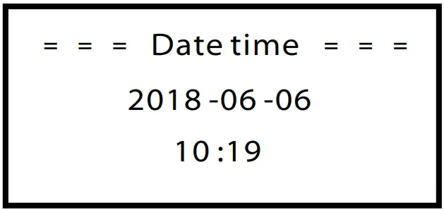
b) Date time
This interface is for user to set the system date and time. Increase or decrease the word by pressing up or down button. Press OK to confirm and alternate to next word. After all the words are confirmed. Press “OK” to enter the date and time.
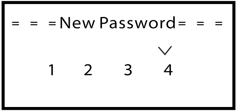
c) New Password
Installer can set the new password here. We need to increase or decrease the word by pressing up or down button. Press OK to confirm and alternate to next word. After word is confirmed., press “OK” to reset the password.
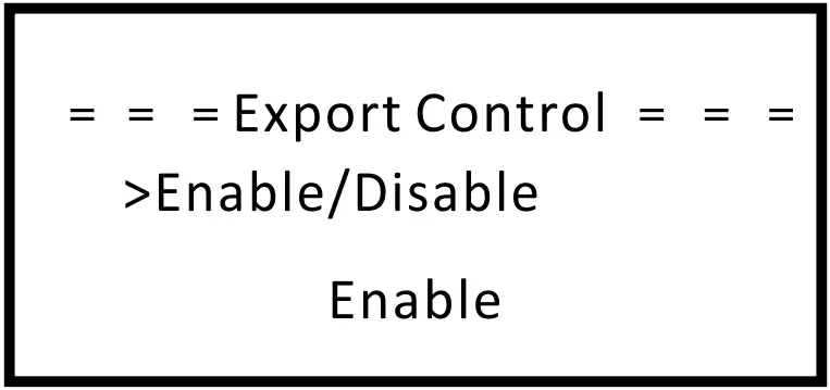
d) Export control
With this function the inverter can control energy exported to the grid.
Whether having this function is based on user’s wishes.
Choose ”Enable” in ”Enable/Disable” means user must install a meter to monitor energy exported to the grid. There are user value and factory value.
The factory value is default which can not be charged by user. The user value setting by installer must be less than the factory value and within the range of 0KW to 20KW.
Choose”Disable” means the function will be shut off.
Press up and down button to select and press”OK” to confirm.
e) Power Factor ( For specific country if required by the local grid.)
There are 6 modes for selecting: Off, Under-Excited, Over-Excited, PF(p), Q( u ), Fixed Q Power. All parameters are shown below.
| Mode | Comment |
| Off | – |
| Under-Excited | PF value |
| Over-Excited | PF value |
| PF(p) | Upper limit |
| Lower limit | |
| Power Upper | |
| Power Lower | |
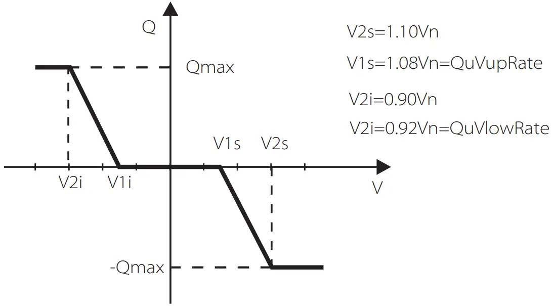
| Q( u ) | QuVupRate |
| QuVlowRate | |
| Fixed Q Power | Q Power |
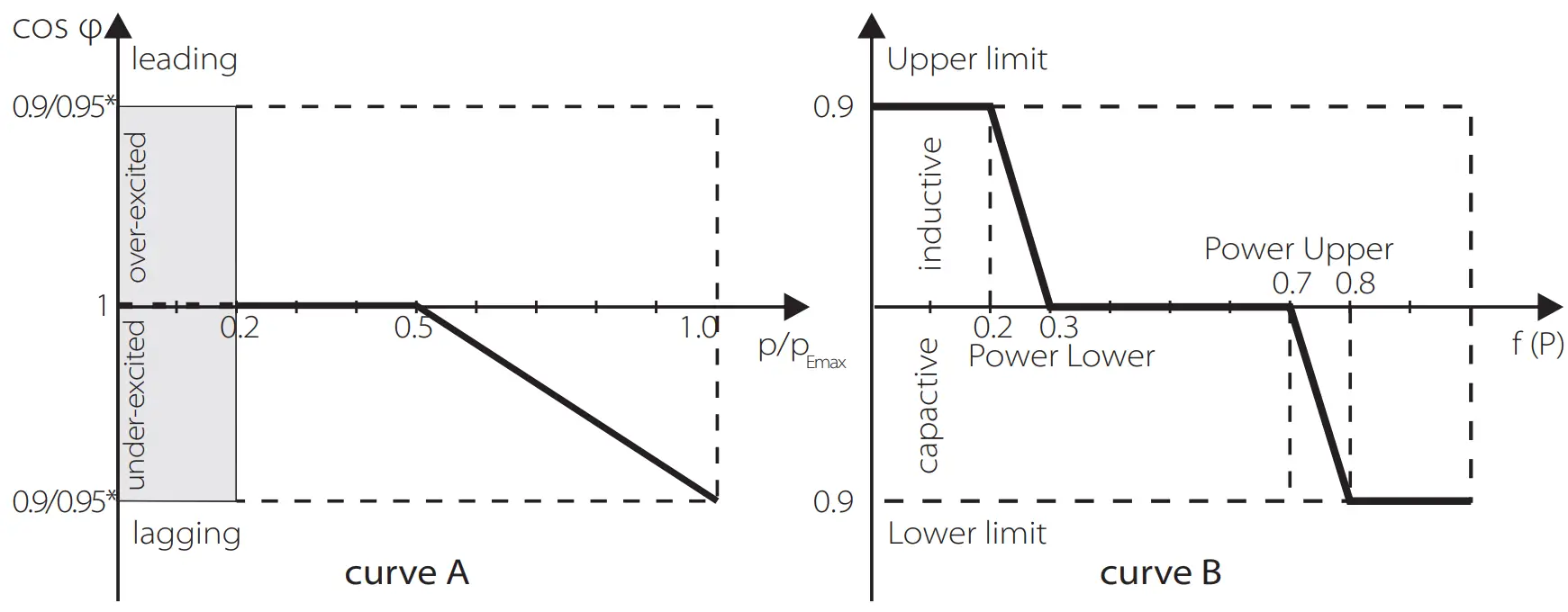
Reactive power control, Reactive standard curve Q= f(V)
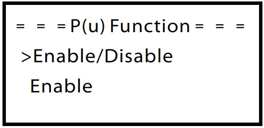
f )P(u) Function
The device is suitable for Australia if the “Enable” is chosen.
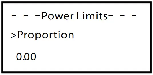
g) Power limits
User can set the power limit here, the setting value is from 0.00-1.00.
h) Grid
Usually end user do not need to set the grid parameters. All default value have been set before leaving factory according to safety rules.
If need to reset, any changes should according to the requirement of local grid.
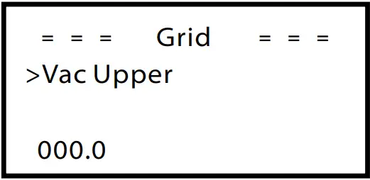
| Parameter | Comment |
| Normally | |
| Vac upper | Voltage high protect |
| Vac lower | Voltage low protect |
| Vac upper slow | Voltage high slow protect |
| Vac lower slow | Voltage low slow protect |
| Fac upper | Frequency high protect |
| Fac lower | Frequency low protect |
| Fac upper slow | Frequency high slow protect |
| Fac lower slow | Frequency low slow protect |
| Vac 10m avg | 10 min voltage high protect |
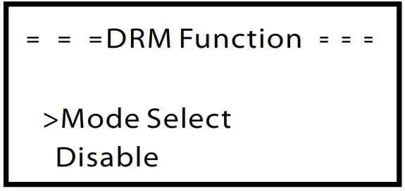
i) DRM Function
User can choose whether using the DRM function or not.
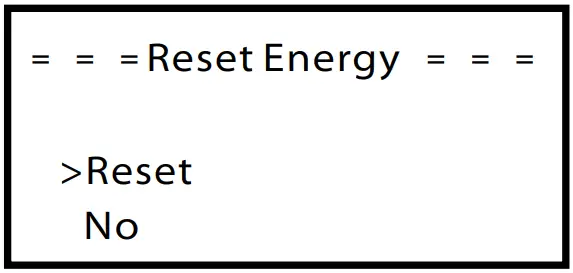
 j) Reset energy
User can reset the energy record here. Press up or down button to select and press “OK” to confirm.
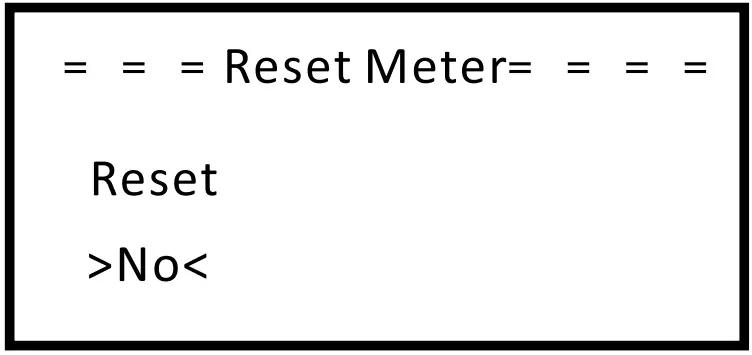
k) Reset meter
User can reset the meter. Press up or down button to select and press “ok” to confirm. (User can Select “Yes” to reset meter if user purchase SolaX meter)
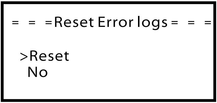
 l) Reset error logs
User can reset the error log here. Press up or down button to select and press “OK” to confirm.
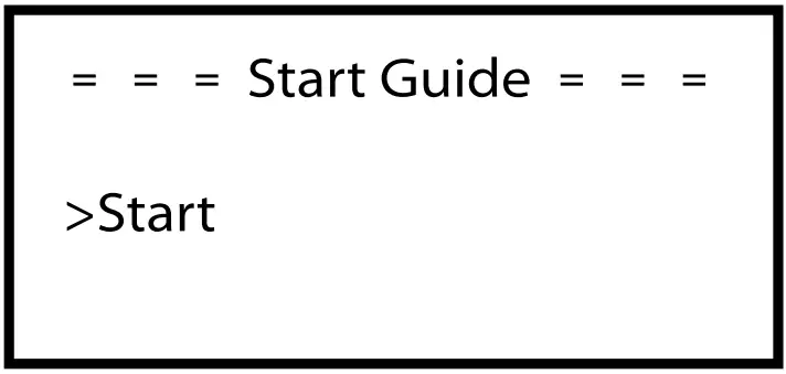
m) Start guide
This interface makes user set initial setting of the inverter again possible.
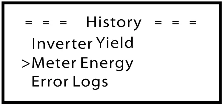
● History
The history function contains four aspects of the information: Inverter yield, load consume, feed in energy and error logs.
Press up and down to select ,and press “OK” to confirm the selection, press “ESC” to return to Menu.
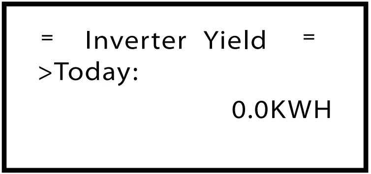
a) Inverter Yield
The inverter yield function contains energy generated by today, this month and total.
Press up and down button to review the parameter, Press “ESC” to return to history.
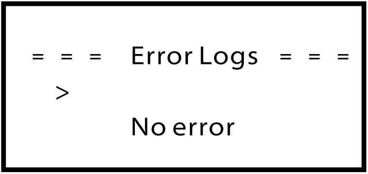
d) Error logs
The Error log contains error information happened, It can record for six items.
Press up and down button to review parameter, Press“ESC” to return to History.
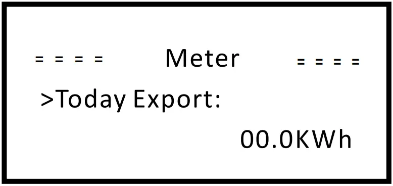
c) Meter
This function is made user check meter energy possible. (Meter energy will show if user use SolaX meter)
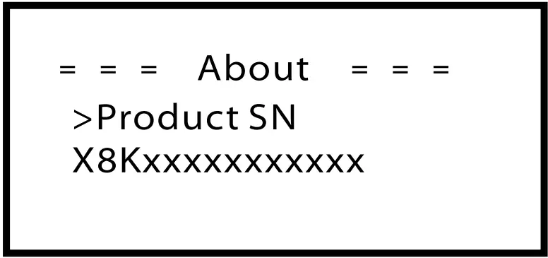
●About
This interface shows information of the inverter, include product Unregister SN, machine type, master and manager.
Troubleshooting
7.1 Trouble shooting
This section contains information and procedures for solving possible problems with X1 series inverters, and provides you with troubleshooting tips to identify and solve most problems that could occur with the X1 series inverters.
This section will help you narrow down the source of any problems you may encounter. Please read the following troubleshooting steps.
Check warnings or fault messages on System Control Panel or Fault codes on the inverter information panel. If a message is displayed, record it before doing anything further.
Attempt the solution indicated in below table.
| Faults | Diagnosis and solution |
| SPI Fault | SPI communication fault •Disconnect PV+ , PV-, reconnect them. •Or seek help from us, if can not go back to normal state. |
| SCI Fault | SCI communication fault •Disconnect PV+ , PV-, reconnect them. •Or seek help from us, if can not go back to normal state. |
| Inv EEPROM Fault | Inverter EEPROM fault •Disconnect PV+ , PV-, reconnect them. •Or seek help from us, if can not go back to normal state. |
| Relay Fault | Relay Fault •Disconnect PV+ , PV-, reconnect them. •Or seek help from us, if can not go back to normal state. |
| Sample Fault | The detection circuit Fault •Disconnect PV+ , PV-, reconnect them. •Or seek help from us, if can not go back to normal state. |
| RCD Fault | Residual Current Device Fault •Check the impedance of DC input and AC output. •Disconnect PV+ , PV-, reconnect them. •Or seek help from us, if can not go back to normal state. |
| Faults | Diagnosis and solution |
| TZ Protect Fault | Over current Fault. I • Wait for a while to check if go back to normal status. •Disconnect PV+ , PV-, reconnect them. •Or seek help from us, if can not go back to normal state. |
| Grid Lost Fault | 1 Grid is Lost. •System will reconnect if the utility is back to normal. •Or seek help from us. |
| Grid Volt Fault | I Grid Voltage Out of Range •System will reconnect if the utility is back to normal. •Or seek help from us. |
| Grid Freq Fault | 1 Grid Frequency out of range •System will reconnect if the utility is back to normal. •Or seek help from us. |
| PLL Lost Fault | The Grid is Not Good. •System will reconnect if the utility is back to normal. •Or seek help from us. |
| Bus Volt Fault | Bus Voltage out of Normal Range. •Disconnect PV+ , PV-, reconnect them. •Check if the PV input is within the range of the inverter. •Or seek help from us, if can not go back to normal state. |
| Inv OCP Fault | Inverter over current protection fault •Wait for a while to check if back to normal. •Or seek for help from us. |
| DCI OCP Fault | DCI over current protection Fault. •Wait for a while to check if back to normal. •Or seek for help from us. |
| PV Volt Fault | PV Voltage Fault •Check the output of the PV voltage. •Or seek for help from us. |
| Isolation Fault | Isolation Fault •Check the connection of the inverter. •Or seek for help from us. |
| Temp Over Fault | Temperature over the limitation •Check if the fan is running normally. •Check if the envirement temperature is over limitation. •Or seek help from us. |
| RC Fault | Residual Current Fault •Wait for a while to check if back to normal. •Or seek for help from us. |
| Other device Fault | Other device fault. •Turn off the PV and grid, reconnect them, •Or seek for help from us if can not back to normal. |
| SW OCP Fault | Over current fault detected •Turn off the PV anc •Or seek for help from | ||
| Vgr EEPROV Fault | Vanager EEPROV Fault. •Turn off the PV and grid, reconnect them, •Or seek for help from us if can not back to normal. | ||
| AC1 C VI Volt Fault | AC1 °Minute overvoltage Fault •System will reconnect if the utility is back to normal. •Or seek help from us. | ||
- If your inverter’s information panel is not displaying a Fault light, check the following list to make sure that the present state of the installation allows proper operation of the unit.
- Is the inverter located in a clean, dry, adequately ventilated place?
- Have the DC input breakers been opened?
- Are the cables adequately sized ?
- Are the input and output connections and wiring in good condition?
- Are the configurations settings correct for your particular installation?
- Are the display panel and the communications cable properly connected and undamaged?
Contact Solax Customer Service for further assistance. Please be prepared to describe details of your system installation and provide model and serial number of the unit.
7.2 Routine maintenance
Inverters do not need any maintenance or correction in most condition, but if the inverter often loses power due to overheating, this can be the following reason:
● The cooling fins on the rear of house are covered by dirt’s.
Clean the cooling fins with a soft dry cloth or brush if necessary.
Only trained and authorized professional personnel who are familiar with the requirements of safety was allowed to perform servicing and maintenance work.
► Safety checks
Safety checks should be performed at least every 12 months by manufacturer’s qualified person who has adequate training,knowledge,and practical experience to perform these tests. The data should be recorded in an equipment log. If the device is not functioning properly or fails any of testate device has to be repaired. For safety check details ,refer to this manual, section 2 Safety instruction and EC Directives.
►Maintain periodically
Only qualified person may perform the following works.
During the process of using the inverter, the manage person shall examine and maintain the machine regularly. The concrete operations are follow.
- Check that if the cooling fins on the rear of house are covered by dirt’s, and the machine should be cleaned and absorbed dust when necessary.
This work shall be check time to time. - Check that if the indicators of the inverter are in normal state, check if the keys of the inverter are in normal state, check if the display of the inverter is normal. This check should be performed at least every 6 months.
- Check that if the input and output wires are damaged or aged. This check should be performed at least every 6 months.
- You should get the inverter panels cleaned and their security checked at least every 6 months.
Decommissioning
8.1 Dismantling the Inverter
Disconnect the inverter from DC Input and AC output.
Wait for 5 minutes for de-energizing.
Disconnect communication and optional connection wirings.
Remove the inverter from the bracket.
Remove the bracket if necessary.
![]() Warning!
Warning!
Before dismantling the inverter, please be sure to disconnect the DC switch, and then unplug the PV and AC cables, otherwise it will lead to an electric shock hazard.
8.2 Packaging
If possible, please pack the inverter with the original packaging.
If it is no longer available, you can also use an equivalent carton that meets the following requirements.
- Suitable for loads more than 30 kg.
- Can be fully closed.
8.3 Storage and Transportation
Store the inverter in dry place where ambient temperatures are always between -25°C~+60°C.Take care of the inverter during the storage and transportation, keep less than 4 cartons in one stack.
When the inverter or other related components need to be disposed. Have it carried out according to local waste handling regulations. Please be sure to deliver wasted inverters and packing materials to certain site, which can assist relevant department to dispose and recycle.
![]() SolaX Power Network Technology(Zhe jiang) Co., Ltd.
SolaX Power Network Technology(Zhe jiang) Co., Ltd.
No.288 Shizhu Road, Tonglu Economic Development Zone,
Tonglu City, Zhejiang province, China.
Tel: +86 0571-56260011
E-mail: [email protected]
www.solaxpower.com
614.00368.02


