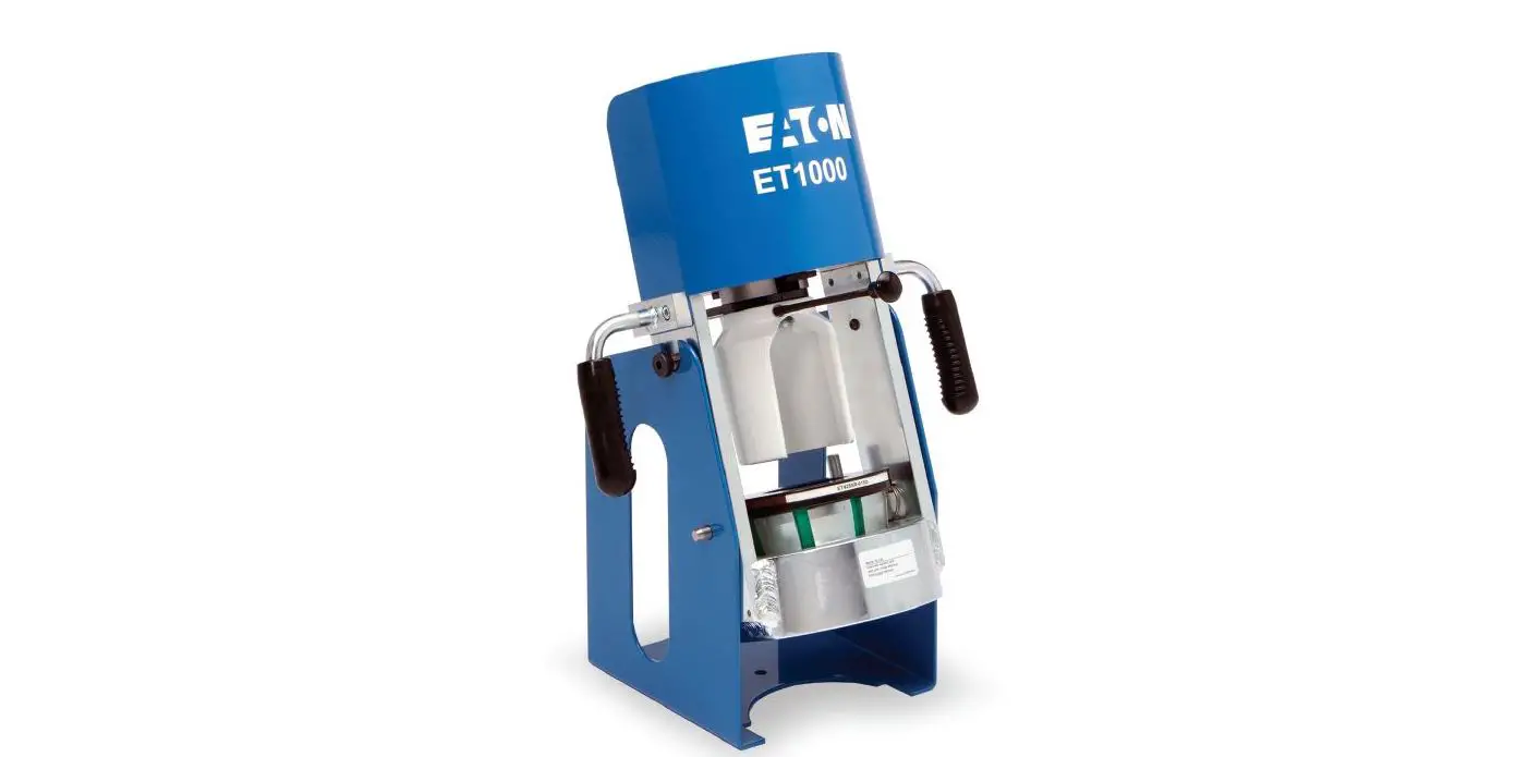
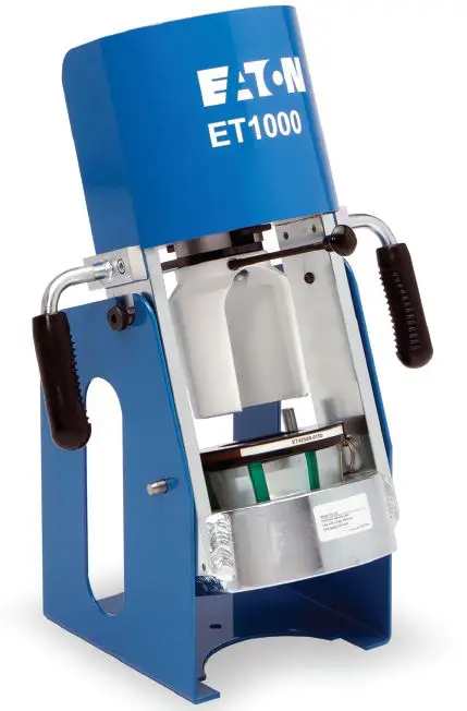
EATON ET1000 Crimp Machine
Safety instructions
Read and understand the operator’s manual before attempting to operate any equipment.
- WARNING
Eaton’s hose and Eaton hose fittings should only be assembled using Eaton’s approved assembly equipment. Do not use any combinations of Eaton’s hose, Eaton hose fittings, or Eaton assembly equipment with hose, hose fittings, or assembly equip-ment supplied by another manufacturer.
Eaton hereby disclaims any obligation or liability (including incidental and consequential damages) arising from breach of contract, warranty, or tort (under negligence or strict liability theories) should Eaton hose, Eaton hose fittings, or Eaton assembly equipment be used with any hose, hose fittings, or assembly equipment supplied by another manufacturer, or in the event that product instructions for each specified hose assembly are not followed. (Reference SAE J1273 – Recommended practice for hydraulic hose assemblies). - WARNING
Failure to follow Eaton processes and product instructions and limitations could lead to premature hose assembly failures, resulting in property damage, serious injury, or death.
Eaton fitting tolerances are engineered to match Eaton’s hose tolerances. The combination or use of Eaton’s hose and hose fittings supplier by another manufacturer may result in the production of unreliable and/or unsafe hose assemblies and is neither recommended nor authorized by Eaton.
- PREVENT UNAUTHORIZED OPERATION. Do not permit anyone to operate this equipment unless they have read and thoroughly understand this manual.
- WEAR SAFETY GLASSES.
- AVOID PINCH POINTS. Do not rest your hand on the crimp ring. Keep your hands clear of all moving parts.
Do not allow anyone, other than the operator, close to the equipment while it is in operation. - MAINTAIN DIES WITH CARE. Dies used in the ET1000 crimp machine are sintered powdered metal, offering the best combination of strength and wear resis-tance for long life. Sintered powdered metal dies are generally brittle and care should be taken to avoid any sharp impact. Never strike a die with a hardened instrument.
- USE ONLY SPECIFIED EA-TON PRODUCTS. Make hose assemblies using only Eaton hose and fittings specified for this assembly equipment.
- VERIFY CORRECT CRIMP DIAMETERS. Check and ver-ify correct crimp diameters of all fittings after crimping. Do not put any hose assemblies into service if the crimp diameters do not meet Eaton crimp specifications
- Make sure all dies are completely in place, the spacer ring rests against the placement pins, and the pusher is pulled forward into the detent position before crimping.
- DO NOT OVER PRES-SURIZE. Do not exceed the 10,000 psi hydraulic pressure supplied to the machine. NOTE: All components used to connect the pump and crimp cylinder must meet the criteria set forth in the Mate-rial Handling Institute Specification #IJ100 for hydraulic jacking applications.
- DIE CHANGE. DO NOT INSERT/REMOVE DIES WHILE THE POWER IS ON OR THE MACHINE IS IN OPERATION.
- SECURE THE EQUIPMENT TO A STABLE WORK SURFACE. Prior to operation, secure the crimp machine to a stable work surface to prevent the equipment from tipping.
- UNPLUG THE POWER SUPPLY WHEN NOT IN USE
- KEEP WORK AREA CLEAN. Cluttered areas and benches invite accidents
Specifications and accessories
ET1000 Crimp machine and accessories
NOTE:
Your new crimp machine has been calibrated and filled with hydraulic oil in the factory. Do not remove any plugs or caps until necessary. Excess air in the hydraulic system may cause erratic cylinder move-ment during retraction. Refer to the Setup and Assembly section for instructions on re-moving air from the hydraulic system.
Specifications
- Crimper Dimensions: 22” tall x 16” width x 14” deep
- Weight: 70 lbs. (machine & stand only)
- Pump Requirements:
- Reservoir Capacity: 36 cu. in (590 cc)
- Pressure Rating: 10,000 psi (690 bar)
- The air/hydraulic pump requires a minimum of 100psi to operate at maximum efficiency.
Hose Production Capacity: Crimps up to -16 in braided and spiral hydraulic hose with core tooling and up to -20 in braided hose using non-core, specialty tooling.
Accessories
- Bench mount bracket (Part # ET1000C-0001)
- Truck/wall mount bracket (Part # ET1000C-0021)
- 1.5 oz. tube high-efficiency PTFE grease ( Part # T-400-G)
- 16 oz. can high-efficiency PTFE grease (Part # FF91455)
- Handle kit includes 2 easy-grip handles with mounting hardware (Part # ET1187C-0028)
- The portability kit includes 2 easy-grip handles with mounting hardware, longer hose assembly, and FF series quick disconnect couplings (Part # ET1187C-0029)
Available pump options:
- Hand pump kit (Part #ET1000PK-001)
- Air/hydraulic pump kit (Part #ET1000PK-002)
- 110v electric pump kit (Part #ET1000PK-003)
- 12v DC electric pump kit (Part #ET1000PK-004)
Note: These pump kits include the pump, connecting hose assembly, and all of the adapters necessary to connect the pump to the ET1000 crimp machine.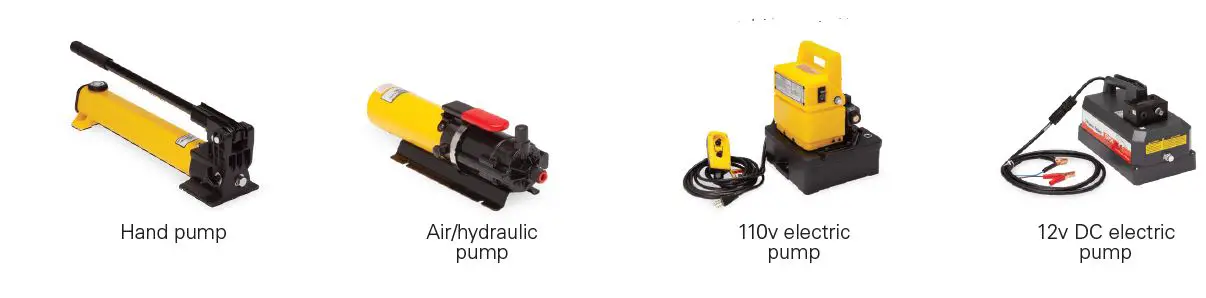
Setup and Assembly
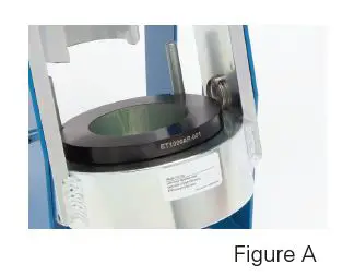
- Your new ET1000 crimp machine comes disassembled for ease of shipment. Before use, the machine must be assembled to the base with the supplied quick release pins. Pins should be installed from the inside of the machine to avoid any contact between the pins and tooling during the crimping process (See Figure A).
- Remove the plug from the top cylinder port and install the –06 size ORB, 90-degree adapter using 23-24 ft. lbs. assembly torque. Orient the adapter so that it points to the rear of the crimp machine, away from the operator.
- Install the pump con-necting hose assembly to the cylinder adapter with the –06 size 37 degree swivel nut fittings using 18-20 ft. lbs. assembly torque.
- Do not exceed an 8” minimum bend radius of the pump connecting hose when attaching the hose to the pump and cylinder.
- If using your own pump, make sure it has the requirements listed in the Specifications section above.
- Place the pump on the work surface to either side of the crimp machine. In-stall the 90 degree adapter to the pump pressure port (Male NPTF threads should be tightened fol-lowing the hex-marking procedure of 2 to 3 turns past hand tight).
- Remove excess air from the hydraulic system. This can be accomplished by placing the pump at a higher level than the cylinder and cycling the machine approximately five times.
- Secure the machine frame to a stable work surface using lag screws or other suitable fasteners.

Operating instructions
ET1000
Description of components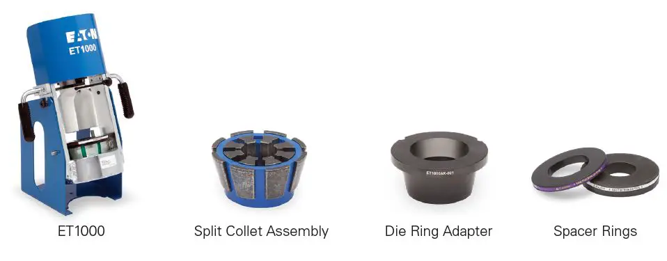
Crimping procedures
Step 1:
Slide the pusher to the back position.
Using the PowerSource crimp spec tool, select the proper collet assembly and spacer ring.
Lubricate the inside cone of the die ring and external surfaces of the collet assembly with a high-efficiency PTFE based lubricant.
Insert the collet assembly into the base die ring.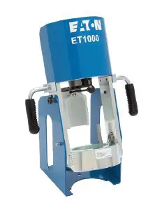
Step 1A:
If using smaller collets, which require an additional adapter ring, lubricate the inside cone of the base die ring and the outside cone of the die ring adapter plate.
Place the die ring adapter plate into the base die ring.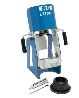
Step 2:
Insert the hose assembly through the bottom of the base die ring and between the two collet assembly halves. Align the fitting with the top of the collet halves.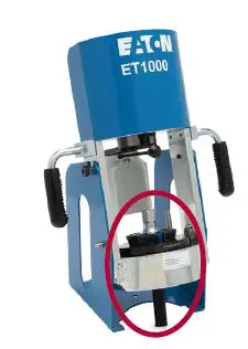
Step 3:
Place the spacer ring in the appropriate position on top of the collet assembly (either flat-side up or flat-side down as referenced in the PowerSource crimp spec tool).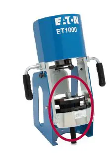 Step 4:
Pull the pusher forward into the detent holding position with the pusher positioning handle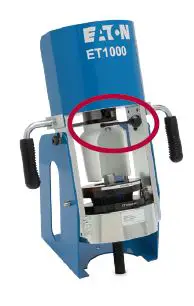
Step 5:
Begin crimping by actuating the pump. When the spacer ring bottoms out against the base die ring, the crimping is complete.
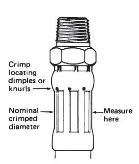
Nominal crimp diameter
Measuring crimp diameters should be a part of the normal hose assembly procedure. To ensure a proper crimp diameter, follow these steps:
- Measure the diameter in the middle of the crimped portion of the hose end. Place the caliper in a position to allow for measurement across the pressed (flat) portion of the crimp.
- Repeat step 1 for each of the remaining sides for a total of four measurements.
- Average the four measurements and compare this average to the target crimp diameter shown in the Power Source crimp spec tool and ensure it falls within tolerance.


Maintenance
Collet Assembly & Die Ring Adapter Plate Lubrication:
Every 30 crimps = Re-lubricate sliding surfaces of dies
Every 250 crimps = Remove old grease and re-lubricate
Machine maintenance procedures
- Sliding surfaces must be kept free of dirt and other abrasive materials.
- All exposed black metal surfaces should be coated occasionally with a light film of oil to prevent corrosion.
Base Die Ring & Die Ring Adapter Plate Maintenance:
Every 250 crimps = Remove old grease and re-lubricate Every 1,000 crimps = Remove old grease, inspect for wear or damage and relubricate if okay. - Some fitting/hose combinations require full pump reservoir capacity to complete the crimp cycle. The oil level in the fluid reservoir of the hydraulic pump should be checked periodically and refilled as required with the pump manufacturer’s hydraulic oil as needed.
NOTE: Completely retract the cylinder when checking the oil level.
Crimp machine components
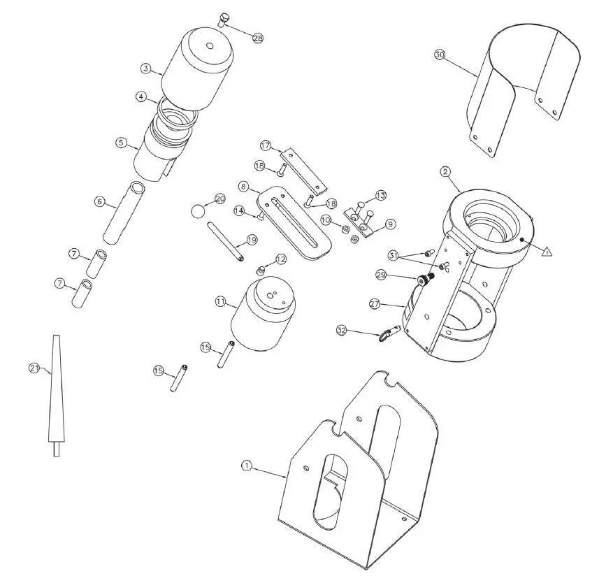
| Item | Part No. | Description | Qty |
| 1 | ET1000C-0001 | Base 1 | 1 |
| 2 | ET1000C-0002 | Die Ring | 1 |
| 3 | ET1000C-0003 | Cylinder Cap | 1 |
| 4 | 140-05691 | T Ring Seal | 1 |
| 5 | ET1000C-0004 | Piston | 1 |
| 6 | ET1000C-0005 | 5 in. Spring | 1 |
| 7 | 140-15962 | 3 1/2 in. Spring | 2 |
| 8 | T-460-SP | Slide Plate | 1 |
| 9 | 140-06924 | Flange Slide Plate | 1 |
| 10 | 140-06925 | Bushing Slide Plate | 2 |
| 11 | ET1000C-0006 | Pusher | 1 |
| 12 | 140-06602 | Detent Screw | 1 |
| 13 | 140-15984-01 | Flat Head Cap Screw | 2 |
| 14 | 140-15984-03 | Flat Head Cap Screw | 2 |
| 15 | 120-70188-41 | Split Roll Pin | 2 |
| Item | Part No. | Description | Qty |
| 17 | 140-05687 | Spring Retainer | 1 |
| 18 | 140-15984 | Flat Head Cap Screw | 2 |
| 19 | 140-05695 | Slide Pull Rod | 1 |
| 20 | 140-05694 | Slide Pull Knob | 1 |
| 21 | T-400-G | Lubricant | 1 |
| 27 | E-EQCR-TE006-E | Lubricator Decal | 1 |
| 28 | FF2138-06S | Plug Assembly | 1 |
| 29 | ET1187C-0014 | Shoulder Screw | 2 |
| 30 | ET1000C-0020 | Shroud | 1 |
| 31 | FF91569 | Cap Screw | 4 |
| 32 | ET1187C-0012 | Quick Release Pin | 2 |
| 33 | 1000EATONDECAL | ET1000 Name Decal | 1 |


