
STANLEY PBD1200 Crimping Tool User Manual
Important
To fill out a product warranty validation form, and for information on your warranty, visit www.stanleyinfrastructure.com and select the Company tab > Warranty.
Note: The warranty validation record must be submitted to validate the warranty.
Warning
SERIOUS INJURY OR DEATH COULD RESULT FROM THE IMPROPER REPAIR OR SERVICE OF THIS TOOL. REPAIRS AND / OR SERVICE TO THIS TOOL MUST ONLY BE DONE BY AN AUTHORIZED AND CERTIFIED DEALER.
SAFETY SYMBOLS
Safety symbols and signal words, as shown below, are used to emphasize all operator, maintenance and repair actions which, if not strictly followed, could result in a life-threatening situation, bodily injury or damage to equipment.
![]() This is the safety alert symbol. It is used to alert you to potential personal injury hazards. Obey all safety messages that follow this symbol to avoid possible injury or death.
This is the safety alert symbol. It is used to alert you to potential personal injury hazards. Obey all safety messages that follow this symbol to avoid possible injury or death.
![]() Danger: This safety alert and signal word indicates an imminently hazardous situation which, if not avoided, will result in death or serious injury.
Danger: This safety alert and signal word indicates an imminently hazardous situation which, if not avoided, will result in death or serious injury.
![]() Warning: This safety alert and signal word indicates a potentially hazardous situation which, if not avoided, could result in death or serious injury.
Warning: This safety alert and signal word indicates a potentially hazardous situation which, if not avoided, could result in death or serious injury.
![]() Caution: This safety alert and signal word indicates a potentially hazardous situation which, if not avoided, could result in death or serious injury.
Caution: This safety alert and signal word indicates a potentially hazardous situation which, if not avoided, could result in death or serious injury.
![]() Caution: This signal word indicates a potentially hazardous situation which, if not avoided, may result in property damage.
Caution: This signal word indicates a potentially hazardous situation which, if not avoided, may result in property damage.
Notice: This signal word indicates a situation which, if not avoided, will result in damage to the equipment.
Important: This signal word indicates a situation which, if not avoided, may result in damage to the equipment.
Always observe safety symbols. They are included for your safety and for the protection of the tool.
LOCAL SAFETY REGULATIONS
Enter any local safety regulations here. Keep these instructions in an area accessible to the operator and maintenance personnel.
SAFETY PRECAUTIONS
Tool operators must comply with precautions given in this manual and on the stickers attached to the tool.
These precautions are given for your safety. Review them carefully before operating the tool.
Supervising personnel should develop additional precautions relating to the specific work area and local safety regulations. Place the added precautions in the space provided on.
The PBD1200 12-Ton crimping tool will provide safe and dependable service if operated in accordance with the instructions in this manual. Read and understand this manual and stickers attached to the tool before operation. Failure could result in injury or tool damage.
- Do not operate the tool unless thoroughly trained or under the supervision of an instructor. Establish a training program for all operators to ensure safe operation.
- Always wear safety equipment such as eye protection, ear protection, head protection and safety shoes at all times when operating the tool. Use gloves if necessary.
- The operator must be familiar with all prohibited work areas such as excessive slopes and dangerous terrain conditions. Ensure that your footing is firm and in balance at all times.
- Do not inspect, clean or replace tool jaw parts while the battery is connected. Accidental engagement of the tool can cause serious injury.
- Do not operate a damaged, improperly adjusted or incompletely assembled tool.
- Never wear loose clothing that can become entangled in the working parts of the tool.
- Keep all parts of your body away from pinch points. Long hair or loose clothing can become drawn into the tool.
- To avoid personal injury or equipment damage, all tool repair, maintenance and service must be performed by an authorized service center.
- Never use the tool in the vicinity of flammable materials or gases.
- Do not use the tool or charge the tool battery in an explosive atmosphere.
- Cutting or severing of body parts is possible if proper procedures are not followed.
- Do not use the tool, battery or battery charger for purposes other than what is described in this manual. Always keep critical tool markings, such as labels and warning stickers, legible. Contact STANLEY for replacement labels.
- Do not use the tool while under the influence of drugs or alcohol.
- Do not use accessories or attachments other than those recommended by STANLEY.
BATTERIES
- Only charge batteries with a STANLEY recommended battery charger.
- Do not store batteries with metal objects, such as coins, nails or keys. Fire can result if battery terminals are shorted.
- Do not charge a damaged battery. Recycle and replace damaged batteries with batteries recommended by STANLEY.
- Do not incinerate or dispose of batteries in the garbage. Recycle the batteries.
- Do not expose the battery to temperatures over 265°F. Batteries may explode at high temperatures.
- Leakage of liquid from the battery may occur under extreme use or high temperatures. If battery liquid gets on your skin:
- Wash quickly with soap and water.
- If the liquid gets in your eyes, flush your eyes with clean water for 10 minutes. Seek medical attention immediately.
- Never open the battery.
BATTERY CHARGER
- Do not use the battery charger if the cord is damaged.
- Do not place the charger, or set items on or near the charger, in such a way as to block airflow to the charger.
- Do not use the charger with an extension cord unless absolutely necessary. Use a cord with the proper wire size for its length, as described in Table 1.
Length of Cord (Feet) 25 50 100 150 Wire Size (AWG) 18 18 18 16 Table 1: Extension Cord Wire Size
- Do not open the charger or attempt to modify it in any way.
- Disconnect the charger from power before attempting to clean it.
- Do not connect the charger to a transformer or engine generator.
TOOL ANATOMY
WHAT IS THE PBD1200 CRIMPING TOOL?
The PBD1200 is a battery powered 12-Ton cable crimping tool with a 1 inch “C” style head. The PBD1200 accepts standard “U” dies and is capable of crimping copper connectors to 500 MCM and aluminum connectors to 636 MCM.
![]() Danger: DO NOT put fingers, hands or other body parts inside the crimping head. Serious injury will result!
Danger: DO NOT put fingers, hands or other body parts inside the crimping head. Serious injury will result!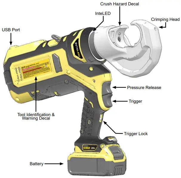
SPECIFICATIONS & ACCESSORIES
SPECIFICATIONS
Crimping Force: 12 Tons (117.6 kN)
Crimping Capacity: Copper Connectors to 500 MCM Aluminum Connectors to 636 MCM
Jaw Type: 1 Inch C Head
Die Type: Standard U Dies
Battery Type: DEWALT 20V Max, 5 amp/hour
Estimated Crimps per Battery Charge: 100
Tool Cycle Time : 6.8 Seconds
Tool Weight: 14.75 Lbs.
Tool Length: 15.5 Inches
Maintenance Interval: 15,000 Cycles
ACCESSORIES
5 Amp/hour DEWALT 20V Max Battery: 81188
120V AC Charger: 81189
12V DC Charger: DCB119
Note: Only use battery chargers recommended by STANLEY.
Bucket Bag: BB01
OPERATION
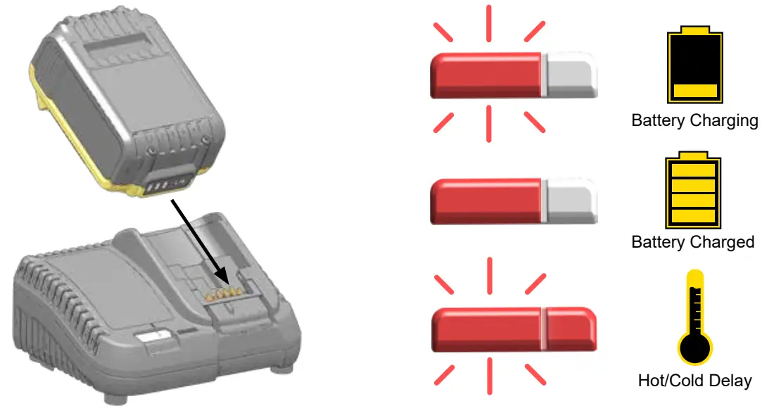
CHARGE BATTERY
USING THE PBD1200
![]() Danger : Set the Trigger Lock BEFORE inserting or removing dies from the Crimping Head.
Danger : Set the Trigger Lock BEFORE inserting or removing dies from the Crimping Head.
- Set the trigger lock.
- Insert battery.
- Insert the die into the crimping head.
- Insert the cable ends into the die.
- Release the trigger lock. Press and hold the trigger until the die is crimped. Press and hold the pressure release to open the crimping head.

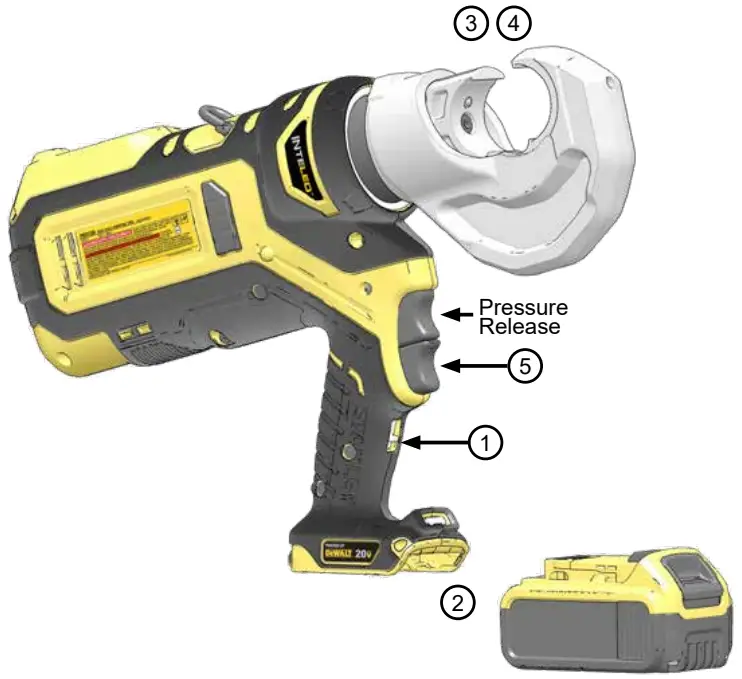
Note: Release the trigger to immediately stop the tool. Press the pressure release at any time to open the jaws.
INTELED SYSTEM
The Inte LED light ring shows you the status of the crimp in real-time.
White: The tool is crimping. Inte LED will stay lit for 30 seconds after the crimp is complete.
Green: The tool has developed full hydraulic pressure during the crimp. The crimp is good.
Red: The tool did not develop full pressure during the crimp. Crimp again.
CHECKING BATTERY CHARGE

STANLEY CRIMP SOFTWARE
STANLEY Crimp software provides valuable data about each crimp. It is also required to update the tool firmware.
INSTALLATION
- Download the STANLEY Crimp software from the STANLEY Infrastructure website.
www.stanleyinfrastructure.com/products/cordless-td
Note: STANLEY Crimp software requires a minimum of Windows XP SP3 running with administrator rights. - Follow the prompts on screen to complete installation.
- Connect PBD1200 to a PC using a micro USB cable.
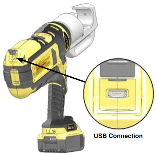
Note: Inte LED will shine blue when connected.
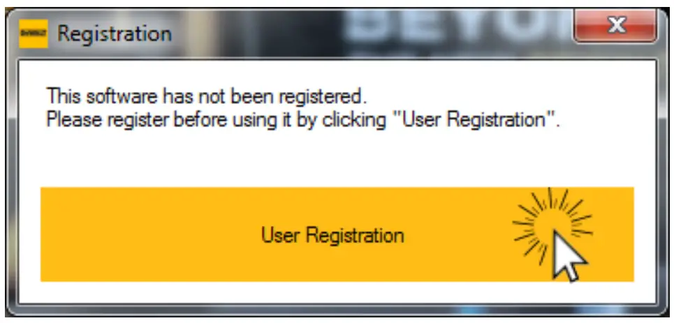
FIRST RUN
- Run the software using the STANLEY Crimp software icon on your Windows desktop.
- You will be prompted to register your software. Left click the “User Registration” button.
- Fill out the registration form and click “Register”.

PBD1200 User Manual ◄ 9
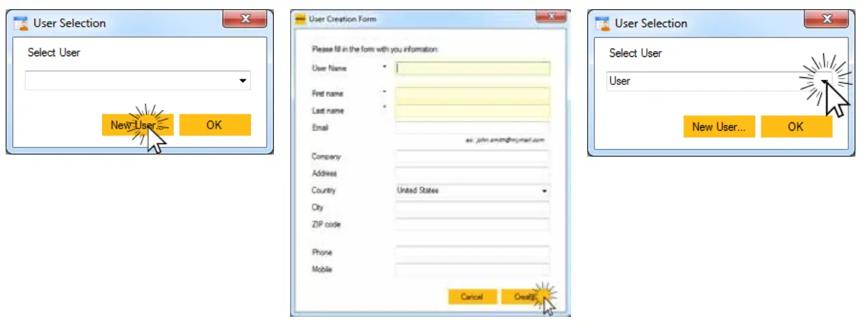
USER SELECTION
- Click the “New User” button
- Enter the required user information and click “Create”.
- Select a user and click “OK”.

TOOL INFORMATION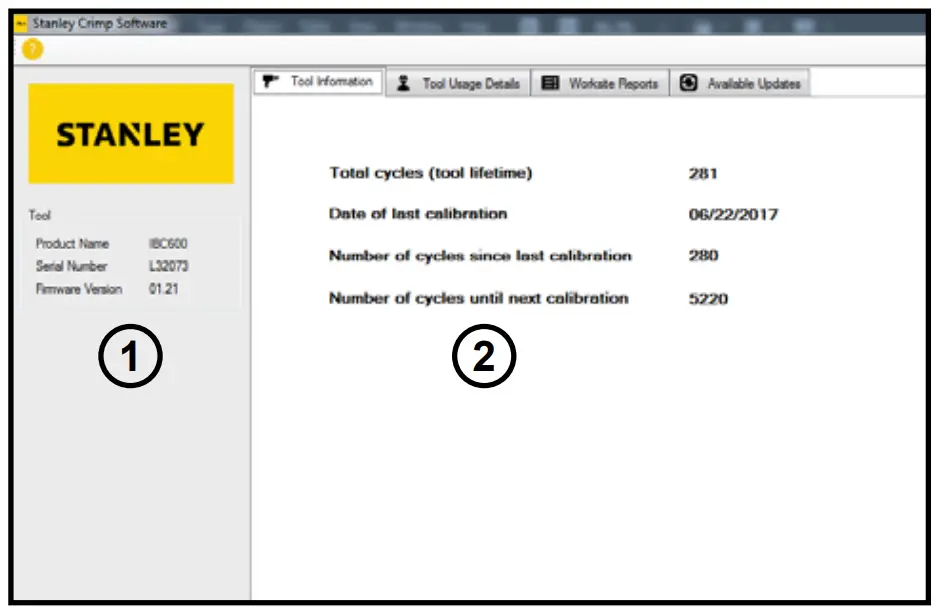
The Tool Information tab displays important data about the PBD1200.
- Displays the product type, serial number and firmware version of the tool.
- Basic data relating to the life and service interval of the tool.
TOOL USAGE DATA
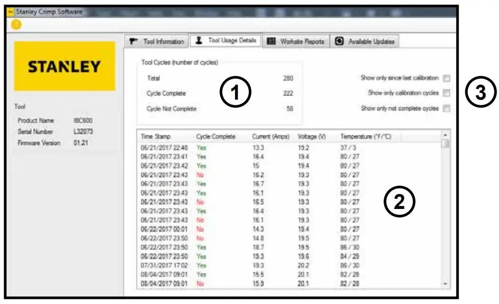
The Tool Usage Data tab displays information about individual tool cycles.
- Displays the total number of tool cycles, as well as completed and incomplete cycles.
- The data log shows each cycle, up to 250,000 cycles. Each entry into the log includes;
- Date and time of each crimp
- If the cycle completed successfully
- Amperage and Voltage of the tool during each crimp
- Tool temperature at the end of each crimp
- The data log shows each cycle, up to 250,000 cycles. Each entry into the log includes;
- Data log sorting filters. Allows you to sort the crimp data in the data log.
WORKSITE REPORTS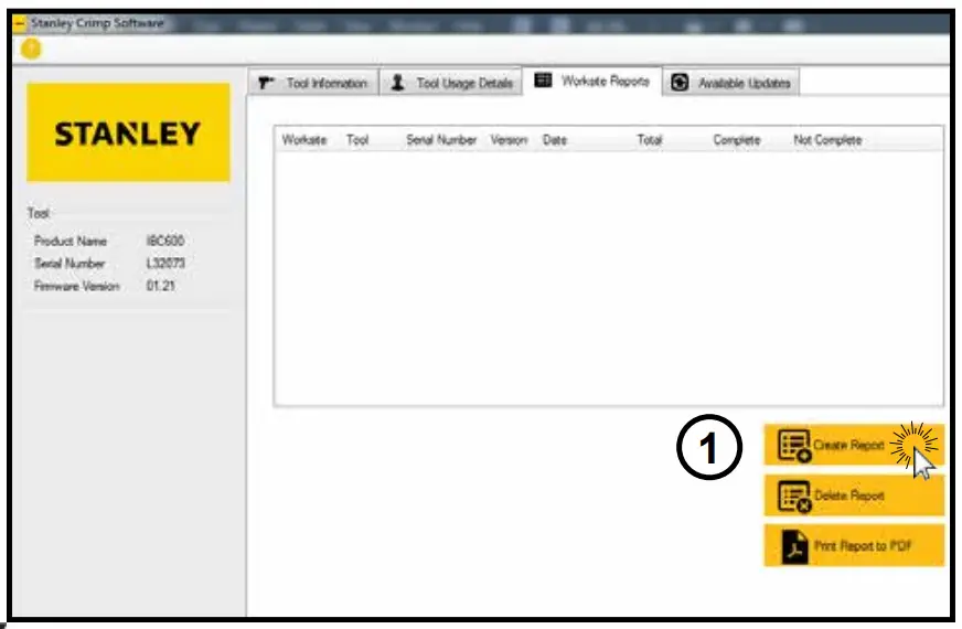
The Worksite Reports tab allows you to group data log entries into a complete tool cycle report.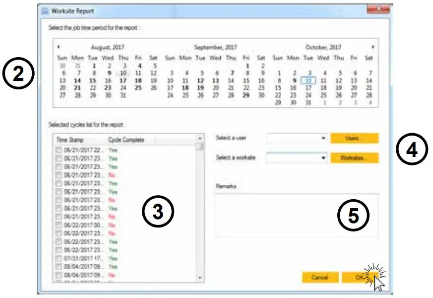
- Click “Create Report”.
- Select the date range of the job you are reporting.
- Select the crimp cycles you want to include in the report.
- Select a user and a worksite.
Note: If this is the first time using the software, press the “Worksites” button to create a worksite. - Enter notes about the job in the Remarks field.
- Click “OK” when finished.

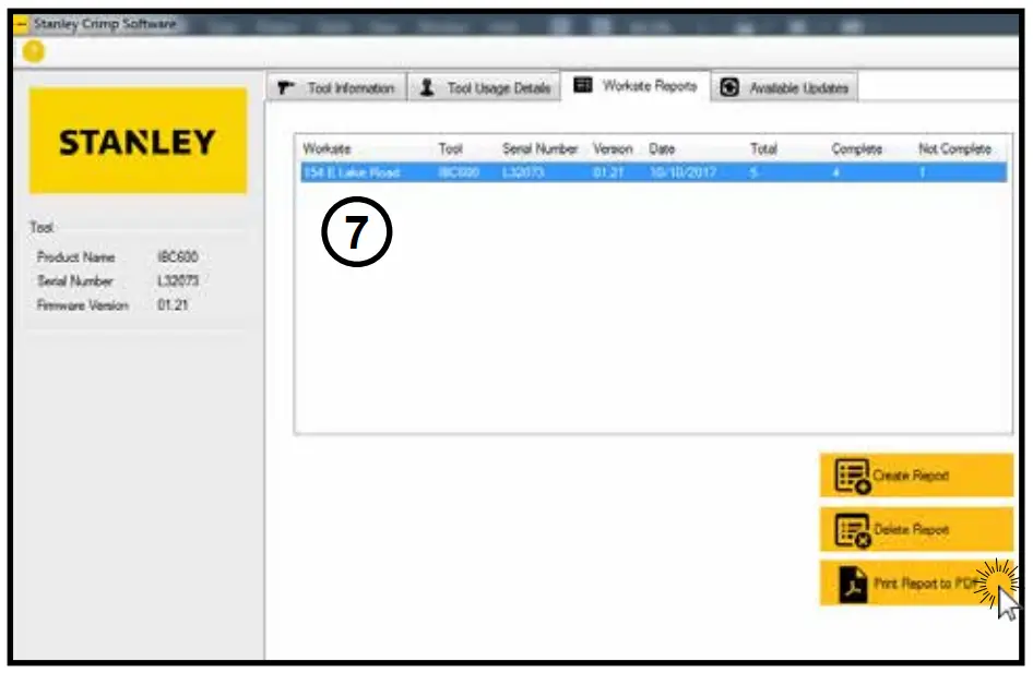
- Select a report from the reports list.
- Click “Print Report to PDF” to export the Worksite Report.
AVAILABLE UPDATES
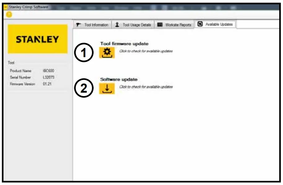
The Available Updates tab will allow you to update the tool firmware and update STANLEY Crimp software.
- Tool Firmware Update button. When clicked, this will begin to tool firmware update process. Do not unplug the tool during this process.
- Software Update button. When clicked, this will update the STANLEY Crimp software, if an update is available.
TROUBLESHOOTING
| Problem | Solution |
| The tool won’t crimp when I press the trigger. | Ensure the battery is charged. Disengage the trigger lock. |
| The InteLED flashes yellow when I activate the tool. | The maintenance interval is about to elapse. Have the tool serviced as soon as possible. |
| The tool repeatedly give me bad crimps / The InteLED flashes red after every crimp. | Ensure the battery is fully charged. Ensure the dies are inserted properly into the crimping head. If problem persists, have the tool serviced as soon as possible. |
| The tool is leaking hydraulic oil. | Have the tool serviced immediately. |
| The tool is not saving data or will not connect to STANLEY Crimp software. | Have the tool serviced as soon as possible. |
PBD1200 PARTS ILLUSTRATION
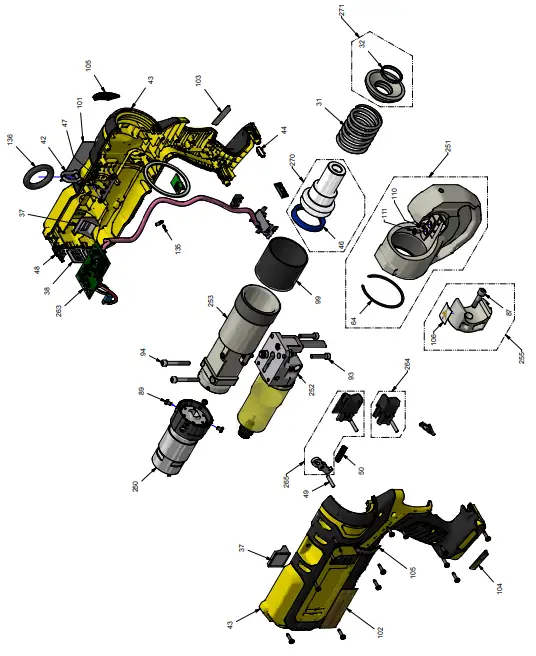
PBD1200 PARTS LIST
| ITEM | P/N | QTY | DESCRIPTION |
| 31 | 85071DUB | 1 | Spring |
| 32 | SGET3100390 | 1 | Guiding Segment |
| 37 | 91649 | 2 | Side Membrane |
| 38 | 91650 | 2 | Rear Membrane |
| 41 | 91655 | 1 | Trigger Lock |
| 42 | 77058-01 | 1 | Shackle |
| 43 | 91593-STA | 1 | Housing Set |
| 44 | 91439 | 1 | Lens LED |
| 46 | JUP404865 | 1 | Lip Seal |
| 47 | 77051-01 | 1 | Shackle Holder |
| 48 | 91410 | 1 | USB Cover |
| 49 | AIG4X19.8BP | 1 | Calibrated Pin |
| 50 | 77061 | 1 | Spring |
| 64 | AAIS60 | 1 | Retaining Ring |
| 87 | VAV06HC025 | 1 | Screw |
| 89 | VAV04CB006 | 4 | Screw |
| 93 | VAV05HC025 | 2 | Screw |
| 94 | VAV05HC040 | 2 | Screw |
| 98 | VAV3.5TC014ZN | 13 | Screw |
| 99 | 91350 | 1 | Protection Cover |
| 101 | 91633 | 1 | Stanley Label |
| 102 | 91638 | 1 | PBD1200 Label |
| 103 | 91634 | 1 | “Powered By De- Walt” label – Right |
| 104 | 91635 | 1 | “Powered By De- Walt” Label – Left |
| 105 | 91636 | 2 | INTELED Label |
| 106 | 91484 | 1 | Crush Hazard Label |
| 110 | 91426 | 1 | Pin |
| 111 | VAV04FH010Z | 1 | Screw |
| 135 | ACKR0204 | 1 | Grooved Pin |
| 136 | 91465 | 1 | Strap Ring |
| 250 | 91856 | 1 | Motor Reduction Unit |
| 251 | 91897 | 1 | Crimping Head Unit |
| 252 | See page 17 | 1 | Reservoir Unit |
| 253 | See page 18 | 1 | Hydraulic Body Unit |
| 255 | 92802C | 1 | Die Holder Unit |
| 263 | 92886 | 1 | Electronic Device |
| 264 | 77853-STA | 1 | Advance Trigger Unit |
| 265 | 77854-DEW | 1 | Release Trigger Unit |
| ITEM | P/N | QTY | DESCRIPTION |
| 270 | 85888C | 1 | Piston Unit |
| 271 | 85884 | 1 | Stop Ring Unit |
PBD1200 RESERVOIR UNIT
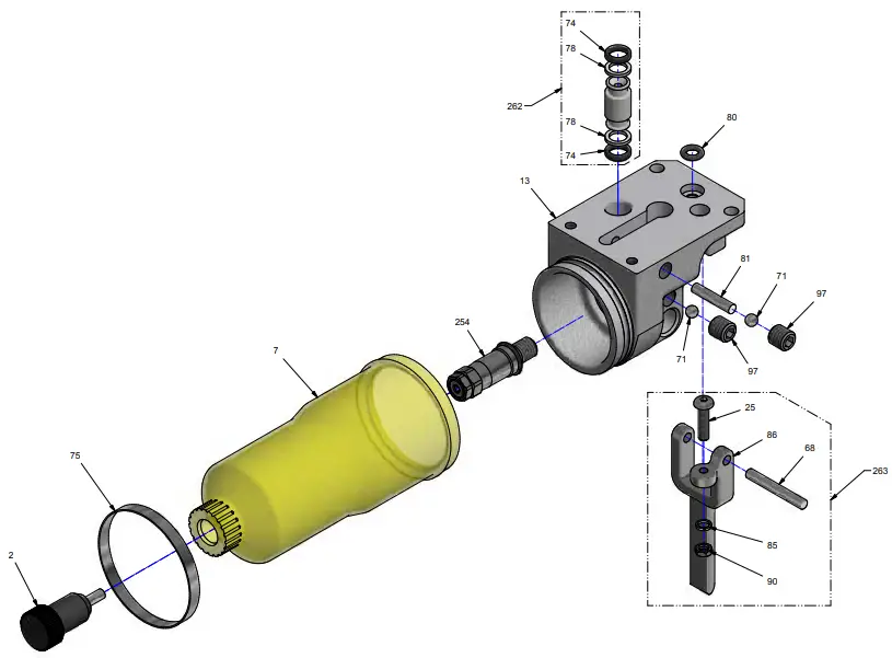
| ITEM | P/N | QTY | DESCRIPTION |
| 2 | 30176DUB | 1 | Reservoir Plug |
| 7 | 91569 | 1 | Oil Reservoir |
| 13 | 77009-02 | 1 | Reservoir Body |
| 25 | VAV04CB015 | 1 | Screw |
| 68 | AIG4X29.8BP | 1 | Calibrated Pin |
| 71 | BILL4.76 | 2 | Ball |
| 74 | J0640190 | 2 | O-Ring |
| 75 | 91576 | 1 | Metal Clamp |
| 78 | JAE0700150 | 2 | Anti-extrusion Ring |
| 80 | J0420250 | 1 | O-Ring |
| 81 | ZBINA420 | 1 | Magnet Pin |
| 85 | VAR04W | 1 | Washer |
| 86 | 91232 | 1 | Release Trigger |
| 90 | VAE04 | 1 | Washer |
| 97 | VAV08BP008 | 2 | Screw |
| 254 | 92884-15 | 1 | Overload Valve |
| 262 | 77851C | 1 | Bodies Connector Unit |
| 263 | 77852-DEW | 1 | Release Lever Unit |
PBD1200 HYDRAULIC UNIT
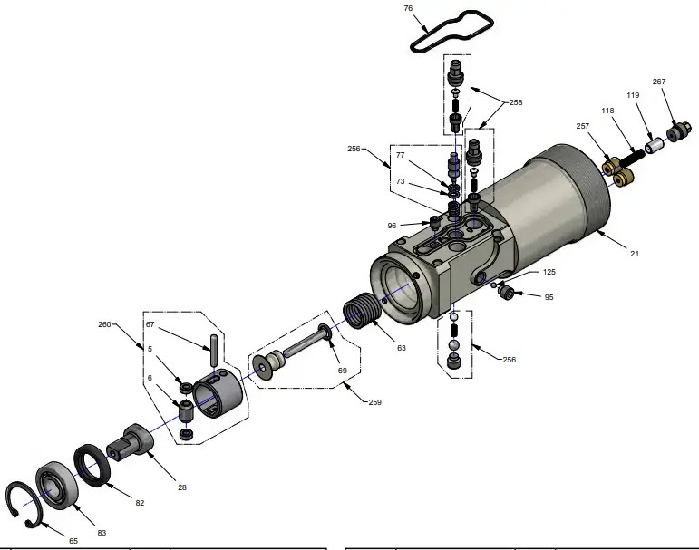
| ITEM | P/N | QTY | DESCRIPTION |
| 5 | 77286 | 2 | Cam Roller |
| 6 | 70048DUB | 1 | Sleeve |
| 21 | 77013-01-AP | 1 | Hydraulic Body |
| 28 | 77026-04 | 1 | Spring |
| 63 | 87213 | 1 | Spring |
| 65 | AAIN30 | 1 | Circlip |
| 67 | AIG4X23.8BR | 1 | Calibrated Pin |
| 69 | J0720190 | 1 | O-Ring |
| 73 | J0290178PU70 | 2 | O-Ring |
| 76 | J4300200 | 1 | O-Ring |
| 77 | JAE0500100 | 1 | Anti-extrusion Ring |
| 82 | JSR1927205 | 1 | Wiper Ring |
| 83 | R1B12.30.08Z | 1 | Ball Bearing |
| 95 | VIV08TT008 | 2 | Screw |
| 96 | VAV06TT008 | 1 | Screw |
| ITEM | P/N | QTY | DESCRIPTION |
| 118 | 77030 | 1 | Spring |
| 119 | 77016 | 1 | Sliding Part |
| 125 | BILL03.175 | 1 | Ball |
| 256 | 77803 | 1 | Release Device |
| 257 | 77805-01 | 2 | Deliver Valve Unit |
| 258 | 77806-01 | 2 | Succion Valve Unit |
| 259 | 77848C-02 | 1 | Spring Collar Unit |
| 260 | 77849C | 1 | Cam Compartment Unit |
| 267 | 77804C | 1 | Commutator |
STANLEY Infrastructure
6430 SE Lake Road
Portland, Oregon 97222 USA
(503) 659-5660 / Fax (503) 652-1780
www.stanleyinfrastructure.com