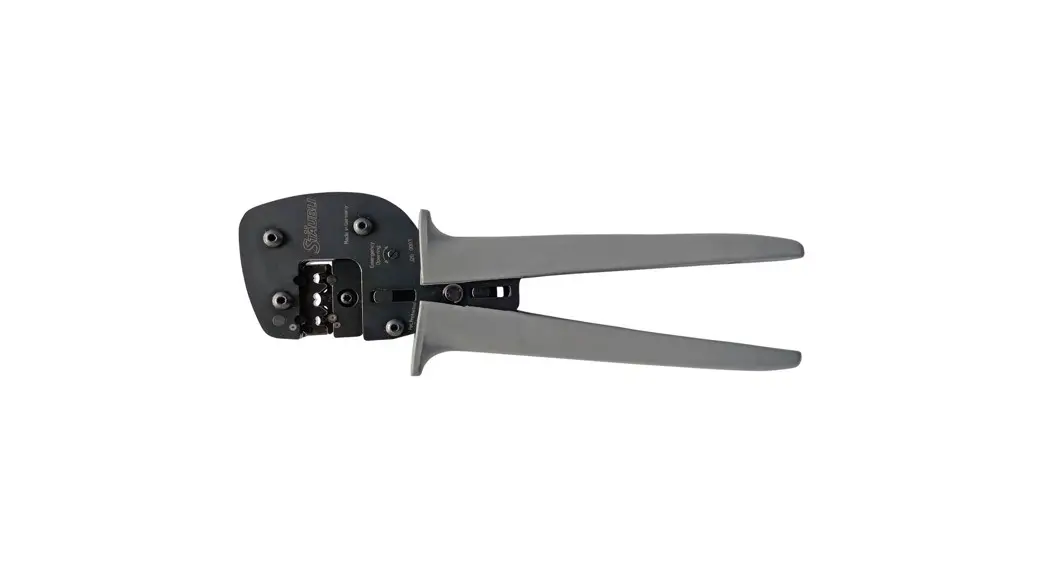
![]() PV-CZM-61100 Crimping Tool
PV-CZM-61100 Crimping Tool
Instruction Manual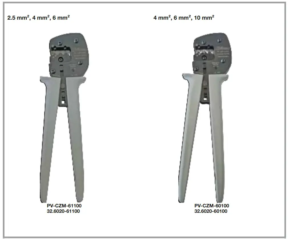
Safety instructions
Importance of the instruction manual
NOT following the instruction manual and safety instructions could result in life-threatening injuries due to electric shock, electric arcs, fire, or failure of the system.
- Follow the entire instruction manual.
Use the product only according to this instruction manual and the technical data.
The digital instruction manual and the technical data are available at: www.staubli.com/electrical
Intended use
The present hand tools are in place to deliver crimp excellence for Stäubli PV connectors with cables. Crimpings shall be carried out only in de-energized state of the cables.
The hand tool is NOT suitable for Live working (IEC 60900).
Scope of delivery
![]() *Note:
*Note:
The harmonised crimping pliers along with the available inserts listed in the above table do not provide any feasible crimping for barrel crimps. Barrel crimps will become unuseable.![]() Note:
Note:
The crimping pliers are not designed for to be used along with crimping terminals PV-KST4/5….; PV-KBT4/5…..;
PV-KST4/8….; PV-KBT4/8…..
See table on page 4….
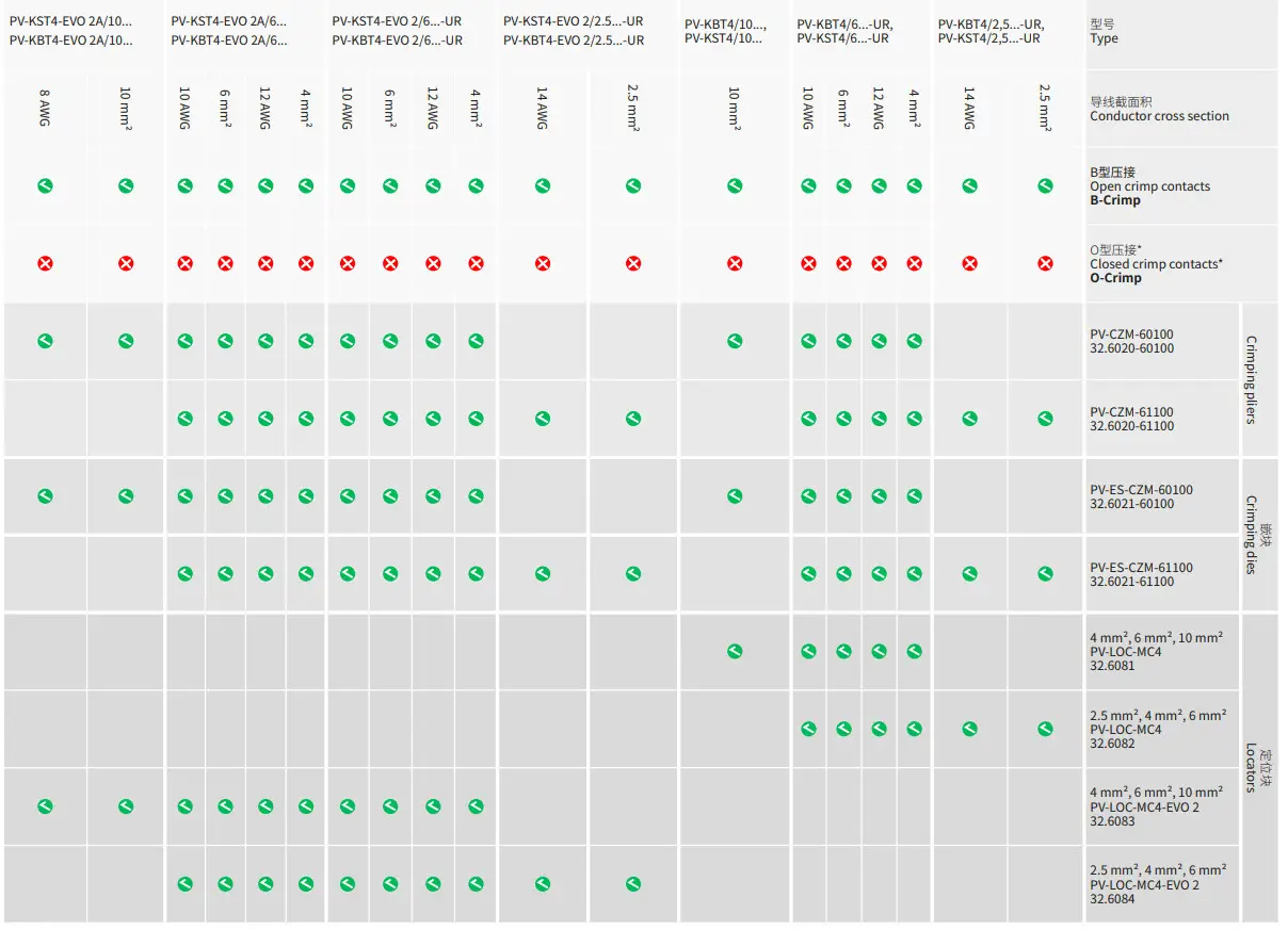
| 1 | 4 | 12 | PV-KST4/6…-UR PV-KBT4/6…-UR PV-KST4-EVO 2/6…-UR PV-KBT4-EVO 2/6…-UR PV-KST4-EVO 2A/6… PV-KBT4-EVO 2A/6… |
| 2 | 6 | 10 | PV-KST4/6…-UR PV-KBT4/6…-UR PV-KST4-EVO 2/6…-UR PV-KBT4-EVO 2/6…-UR PV-KST4-EVO 2A/6… PV-KBT4-EVO 2A/6… |
| 3 | 10 | 8 | PV-KST4-EVO 2/10…-UR PV-KBT4-EVO 2/10…-UR PV-KST4-EVO 2A/10… PV-KBT4-EVO 2A/10… |
| 4 | 10 | – | PV-KST4/10… PV-KBT4/10… |
| 1 | 2.5 | 14 | PV-KST4/2.5…-UR PV-KBT4/2.5…-UR PV-KST4-EVO 2/2.5…-UR PV-KBT4-EVO 2/2.5…-UR PV-KST4-EVO 2A/2.5… PV-KBT4-EVO 2A/2.5… |
| 2 | 4 | 12 | PV-KST4/6…-UR PV-KBT4/6…-UR PV-KST4-EVO 2/6…-UR PV-KBT4-EVO 2/6…-UR PV-KST4-EVO 2A/6… PV-KBT4-EVO 2A/6… |
| 3 | 6 | 10 |
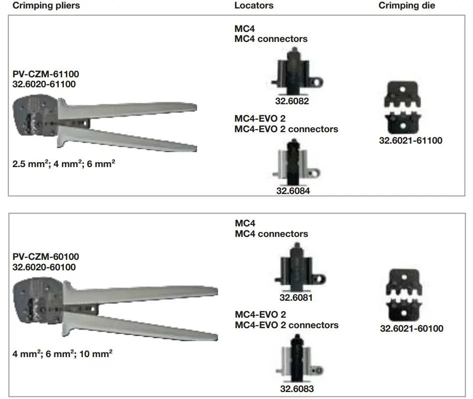
Individual parts
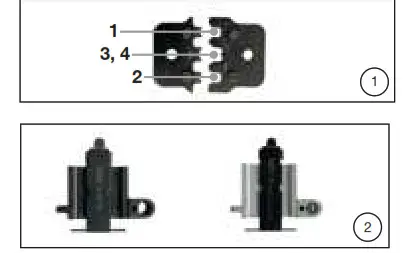
(ill. 1)
Interchangeable crimping die for cable cross sections 4 mm², 6 mm² and 10 mm²
Note:
The crimping pliers are not designed for to be used along with crimping terminals PV-KST4/5…;
PV-KBT4/5….; PV-KST4/8….;
PV-KBT4/8….
See table on page 4…
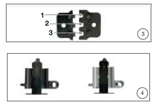
(ill. 2) Locators:
MC4 connectors:
PV-LOC-MC4
Order No. 32.6081
MC4-Evo 2 connectors:
PV-LOC-MC4-EVO 2
Order No. 32.6083
Attention
The locators with black metal body must be used only for MC4 crimp terminals. The locators with grey metal body must be used only for MC4-EVO 2 crimp terminals.
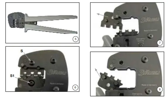
(ill. 3)
Interchangeable crimping die for cable cross sections 2.5 mm², 4 mm² and 6 mm²
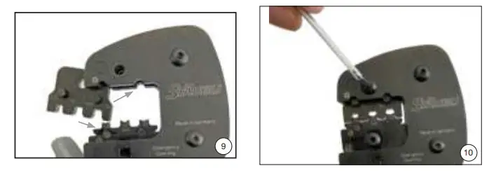
Exchanging the crimping die
Fitting the crimping die
(ill. 9)
The crimping dies can be inserted only when the handles are open Insert the dies separately The laser identification of the dies needs to face towards the operator as well as the pliers identification.
![]() Attention
Attention
When inserting the dies make sure that the anvil (lower die) is inserted first, only then insert the punch.
- Close the pliers
- Place the screws in the correct position. Do not damage the screw heads.
(ill. 10)
Screw in screw S (long) and S1 (short) completely.
Locator assembly
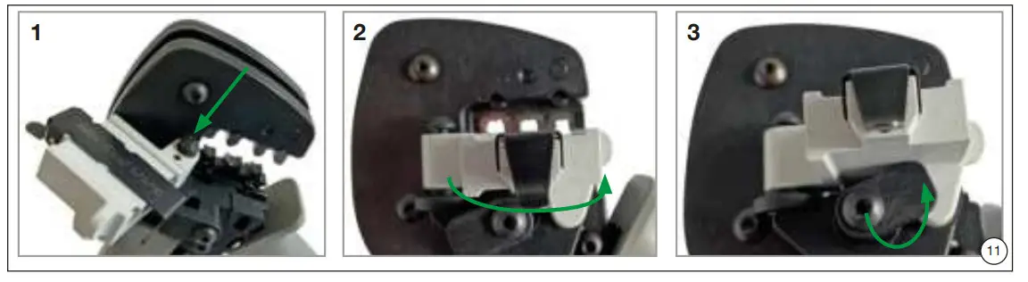
(ill. 11)
- Affix locator onto the guide pin.
- Rotate the locator (held magnetically).
- Lock the locator.
Crimping
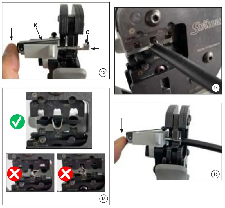
(ill. 12)
- Open clamp (K) and hold tight.
- Insert the contact in the appropriate cross-section range.
- Turn the crimping flaps (C) upwards.
- Release clamp (K).
- The contact is locked.
(ill. 13)
Verify if the crimping flaps are still correctly aligned.
Press the pliers gently together until the crimping flaps are properly located within the crimping die.
(ill. 14)
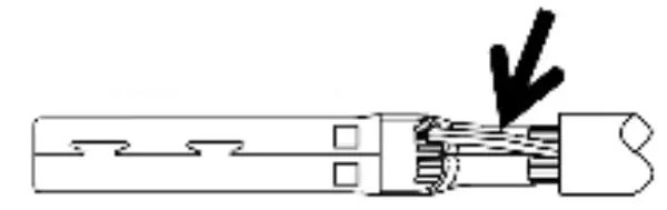
Insert the stripped cable end until the cable strands come up against the clamp.
Completely close the crimping pliers.
Note:
Observe the stripping length of the PV cable supplier. Do not damage strands when stripping the cable.
(ill. 15)
After crimping, move the locator to 0 position and remove contact.
Attention
The crimp terminals shall not be released from the pliers under force.
They should come out easily.
Notes on the correct production of the crimp connection
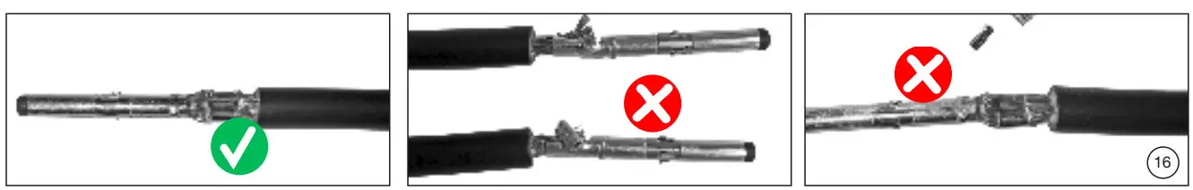
(ill. 16)
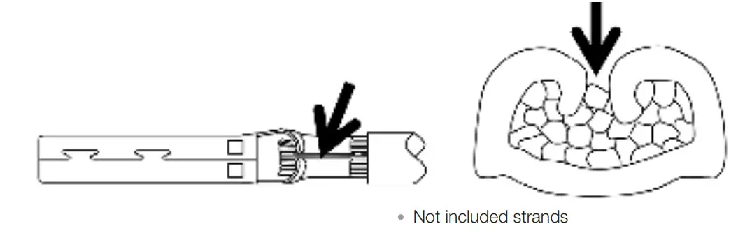
Visually check the crimp according to criteria written in IEC 60352-2.
Confirm that:
- All of the strands have been captured in the crimp sleeve
- The crimp sleeve is not deformed or missing any portion of the crimp flaps
- That the crimp is symmetrical in form
- A “brush” of conductor strands are visible on the contact side of crimp.
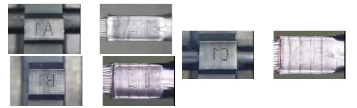
Verify crimp height. Typical values for the crimp height for Stäubli PV cable Flex-Sol-Evo TX and Flex-Sol-Evo DX are listed below: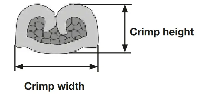
WZ 1 *61100
MC4-Evo 2
| Conductor cross section mm² | Coding | Conductor cross section AWG | Crimp height ± 0.05 mm | Crimp width ± 0.1 mm | Contact type | Order No. |
| 2.5 | A1 | 14 | 1.8 | 3.11 | PV-SP4-EVO 2/2,5 PV-BP4-EVO 2/2,5 | 32.0520P* 32.0120P |
| 4 | B1 | 12 | 2.15 | 4 | PV-SP4-EVO 2/6 PV-BP4-EVO 2/6 | 32.0521P* 32.0121P* |
| 6 | C1 | 10 | 2.4 | 4.28 | PV-SP4-EVO 2/6 PV-BP4-EVO 2/6 | 32.0521P* 32.0121P* |
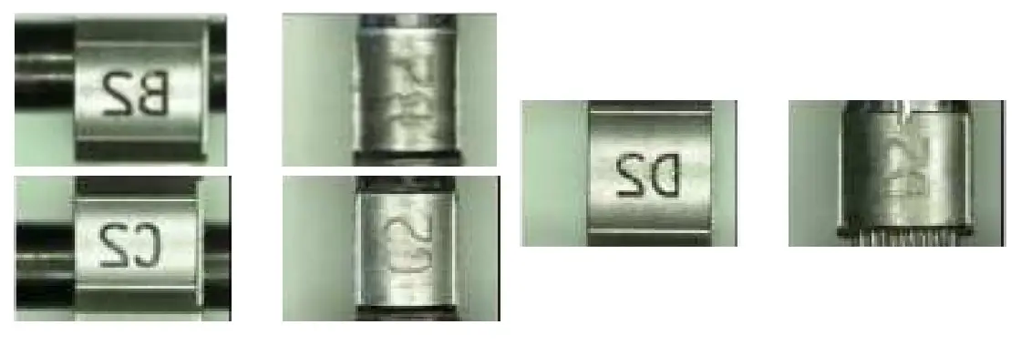
WZ 2 *60100
MC4-Evo 2
| Conductor cross section mm² | Coding | Conductor cross section AWG | Crimp height ± 0.05 mm | Crimp width ± 0.1 mm | Contact type | Order No. |
| 4 | B2 | 12 | 2.15 | 4.2 | PV-SP4-EVO 2/6 PV-BP4-EVO 2/6 | 32.0521P* 32.0121P* |
| 6 | C2 | 10 | 2.4 | 4.28 | PV-SP4-EVO 2/6 PV-BP4-EVO 2/6 | 32.0521P* 32.0121P* |
| 10 | D2 | 8 | 3.02 | 5.65 | PV-SP4-EVO 2/10 PV-BP4-EVO 2/10 | 32.0522P* 32.0122P* |
 *Crimping of 8 AWG (10 mm²) MC4 barrel crimps is not listed in the related connector UL file
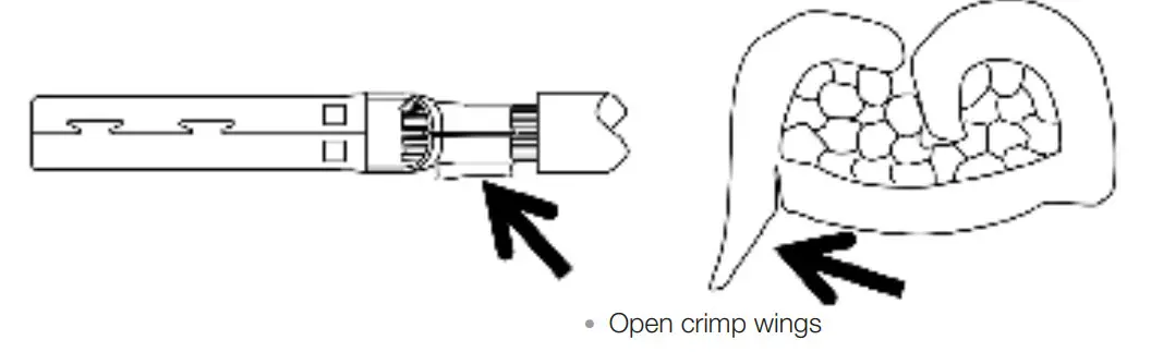
Visual inspection of the crimpings performed
Good crimp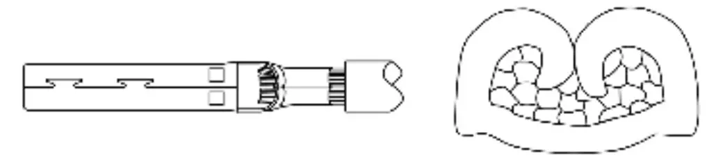
Bad crimps:
- Stamped parts bent wrongly
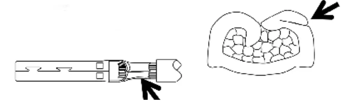
- Material flow outwards


Stockbrunnenrain 8
4123 Allschwil/Switzerland
Tel. +41 61 306 55 55
Fax. +41 61 306 55 56
mail [email protected]
www.staubli.com/electrical


