
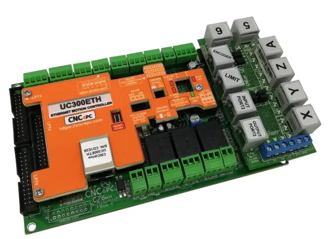
CNC4PC C76 Multifunction CNC Board
FEATURES
- Designed for UC300ETH motion controller.
- 3 Expansion Ports. It has 3 x IDC26 connector for adding Breakout or Relay Boards.
- Built-in PWM-Based Speed Control and Two Built-in Electromechanical Relays with NO and NC positions for spindle control.
The system monitors:
- E-Stop
- Safety Charge Pump.
- VFD Fault.
- Driver Fault.
- Outputs can be 500mA open collector or +5vdc at 50mA TTL.
- Electromechanical Relay with NO and NC positions for general purpose (Port_2 16 or 17, jumper-selectable).
- Microcontroller-based SCHP.
- Optoisolated inputs working at 5-24VDC.
- Can be powered with a voltage between +10 and +30VDC.
- Status LEDs on all input and Output connections.
- DIN Rail mountable.
- Pluggable Screw-On Terminals.
- It is compatible with family of C34 connector boards that allow quickly connecting to popular drives connecting not just the step and direction signals, but also the fault and enable signals.
- High speed input *New
I/O SPECIFICATIONS
Inputs and Outputs are jumper selected to be TTL or Open collector.
| PINS | PORT1 | PORT2 | PORT3 | PORT4 | PORT5 | TOTAL |
| INPUT | 5 | 13 | 13 | 5 | 13 | 49 |
| OUTPUT | 12 | 4 | 4 | 12 | 4 | 36 |
| TOTAL | 17 | 17 | 17 | 17 | 17 | 93 |
| OPTOISOLATED DIGITAL INPUT TTL SPECIFICATIONS | |
| On-state voltage range | 5 to 24VDC |
| Maximum off-state voltage | 0.8V |
| Typical signal delay | 2.8uS |
| DIGITAL OUTPUT TTL SPECIFICATIONS | |
| Maximum output voltage | 5VDC |
| Maximum output current | 24mA |
| Maximum off-state voltage | 0.44 V |
| Maximum supported frequency | 400KHz |
| Typical signal delay | 10nS |
| Time of transition to high impedance state | 12nS |
| OPEN COLLECTOR OUTPUT SPECIFICATIONS | |
| Number of outputs | 4 |
| Maximum Supported output voltage | 50VDC |
| Typical output current (general purpose pins) | 500mA |
| Maximum supported frequency | 250KHz |
| Typical signal delay | Less than 8nS |
| ENCODER INPUT | |
| On-state voltage | 5 VDC |
| Maximum off-state voltage | 0.8V |
| Typical signal delay | 2.8uS |
| Rise / Fall Time (Typ) | 50ns – 12ns |
BOARD DESCRIPTION 
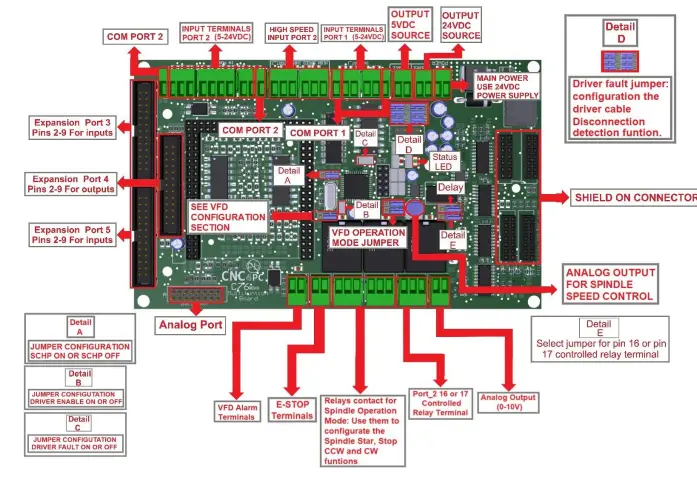
POWER TERMINALS AND CONFIGURATION JUMPERS
Power terminal
The board requires an external power supply which can deliver 10-30VDC@700mA to power the logic of the board and the UC300, but keep in mind that each output can deliver up to 500mA and if powering other breakout or relays boards. So, you will need to add all the expected power consumption. 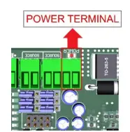
Source Output 5VDC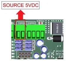
Source Output 10-30VDC
10-30VDC can be sourced to sensors or other cards requiring it.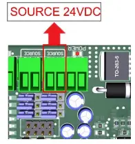
Input terminals for port_1 and port_2
These terminals support signals 10-24VDC, you can connect sensors NPN, PNP, switches, capacitive sensors, etc. set jumpers depending on signal voltage.
PORT_1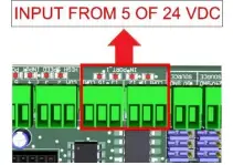
PORT_2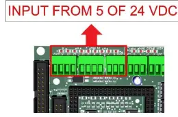
HIGH-SPEED INPUT PORT_2 PIN 2, 3, 4 AND 5
These terminals support signals 5VDC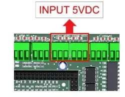
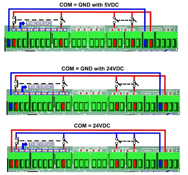
Select inputs of port_1 and port_2
Set COM = +5VDC, GND or 10-24VDC to determine the common for the input signals to be used.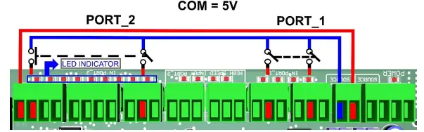
JUMPER POSITION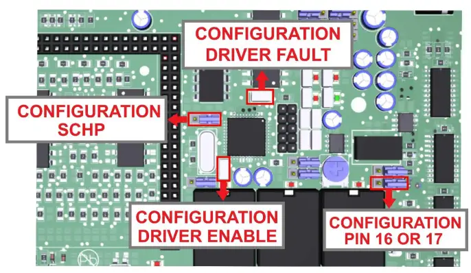
Selecting the SCHP operation mode
The Safety Charge Pump uses pin 17 on port 2. When the SCHP is enabled on the board, then the output of the terminals will be active while the Safety Charge Pump signal is present and inactive while the SCHP is not present. 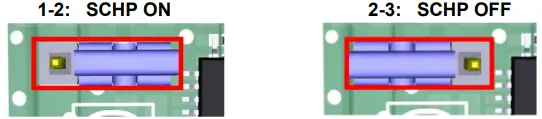
Note: also, that Relay3 on can also be tied to pin 17 or 16 on port 2. If the jumper is set to be tied to pin 17, then the relay will activate while the system is active. This can be ideal to control power to DC servos or to handle servo brakes. Or enable/disable any other feature that is associated to the system been active.
Jumper configuration driver enable
When you need to use the Driver enable to ON put the jumper, if you need it OFF remove the jumper 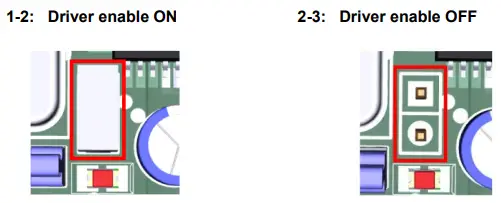
Jumper configuration driver fault
When you need to use Driver Fault to ON set the jumper, if you need to OFF remove the jumper. 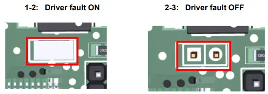
Configuration jumper pin 16 or 17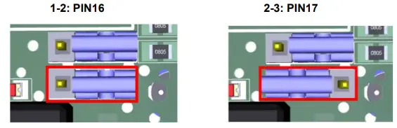
LPT_3 AND LPT 5 INPUT EXPANSION PORT
| LPT 3/LPT 5 | |
| Equivalent P.P. Pin | UC300 Function |
| P_1 | OUTPUT |
| P_2 | INPUT |
| P_3 | INPUT |
| P_4 | INPUT |
| P_5 | INPUT |
| P_6 | INPUT |
| P_7 | INPUT |
| P_8 | INPUT |
| P_9 | INPUT |
| P_10 | INPUT |
| P_11 | INPUT |
| P_12 | INPUT |
| P_13 | INPUT |
| P_14 | OUTPUT |
| P_15 | INPUT |
| P_16 | OUTPUT |
| P_17 | OUTPUT |
| P_18 | ENABLE |
NOTE:
Output pin 18 can be used to enable expansion boards
LPT_4 OUTPUT EXPANSION PORT
| LPT 4 | |
| Equivalent P.P. Pin | UC300 Function |
| P4_1 | OUTPUT |
| P4_2 | OUTPUT |
| P4_3 | OUTPUT |
| P4_4 | OUTPUT |
| P4_5 | OUTPUT |
| P4_6 | OUTPUT |
| P4_7 | OUTPUT |
| P4_8 | OUTPUT |
| P4_9 | OUTPUT |
| P4_10 | INPUT |
| P4_11 | INPUT |
| P4_12 | INPUT |
| P4_13 | INPUT |
| P4_14 | OUTPUT |
| P4_15 | INPUT |
| P4_16 | OUTPUT |
| P4_17 | OUTPUT |
| P4_18 | ENABLE |
ANALOG I/O PORT PINOUT.
The analog port contains 2 analog inputs and 2 analog outputs. This port also contains a 5Volts power output. 
| Pin | Signal direction |
| 1 | 5 Volt output |
| 2 | Ground |
| 3 | Analog input 1. |
| 4 | Analog input 2. |
| 5 | Ground |
| 6 | Analog output 1. |
| 7 | Analog output 2. |
| 8 | 5 Volt output |
| 9 | 5 Volt output |
| 10 | Ground |
| 11 | Analog input 1. |
| 12 | Analog input 2. |
| 13 | Ground |
| 14 | Analog output 1. |
| 15 | Analog output 2. |
| 16 | 5 Volt output |
NOTE:
Analog I/Os are not isolated.
CONNECTION EXAMPLE FOR SHIELD C78
RJ45 shield C78 connection for axes, Limits, and Encoder 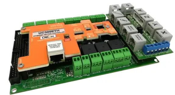
RJ45 shield board description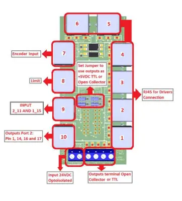
Pinout
RJ45 Distribution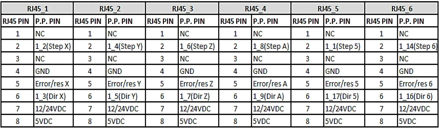
| RJ45_7 | RJ45_8 | RJ45_9 | RJ45_10 | ||||
| RJ45 PIN | P.P. PIN | RJ45 PIN | P.P. PIN | RJ45 PIN | P.P. PIN | RJ45 PIN | P.P. PIN |
| 1 | GND | 1 | GND | 1 | GND | 1 | GND |
| 2 | 5VDC | 2 | 1_13 | 2 | NC | 2 | 2_17 |
| 3 | NC | 3 | 1_12 | 3 | NC | 3 | 2_16 |
| 4 | 2_4(INDEX) | 4 | 1_11 | 4 | 2_11 | 4 | 2_1 |
| 5 | NC | 5 | 1_15 | 5 | 1_15 | 5 | 2_14 |
| 6 | 2_2(enc. A) | 6 | 2_11 | 6 | NC | 6 | NC |
| 7 | NC | 7 | 12/24VDC | 7 | 12/24VDC | 7 | 5VDC |
| 8 | 2_3(enc. B) | 8 | NC | 8 | NC | 8 | 12/24VDC |
CONNECTION EXAMPLE FOR SHIELD C77
Terminal Shield Screw-on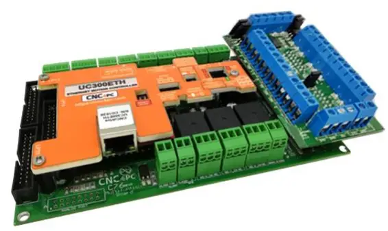
Shield board description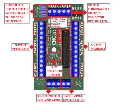
DRIVER DISCONNECTION JUMPERS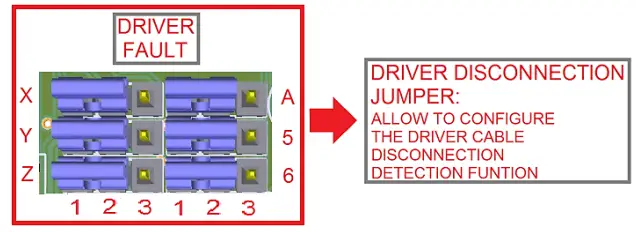
- Note: 1-2: Cable disconnection detection.
- No cable disconnection detection.
- This configures how cable disconnect is to work. Set according to C34 board manual.
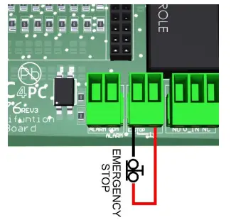
E-STOP TERMINAL
- Connect an E-STOP push button as is shown in the below images.

- Pin 10 port 1 is used for E-Stop. Since this board controls the enable line, and the enable line is the one responsible for notifying the controller of the e-stop condition, the user does not have a direct access to the pin itself, just to the e-stop terminal on the board. The E-Stop terminal is tied to the enable line and will trigger the e-stop. A fault or E-Stop triggers a low for 5 seconds to notify the controller of the fault condition, then resets to high again.
TYPICAL CONNECTIONS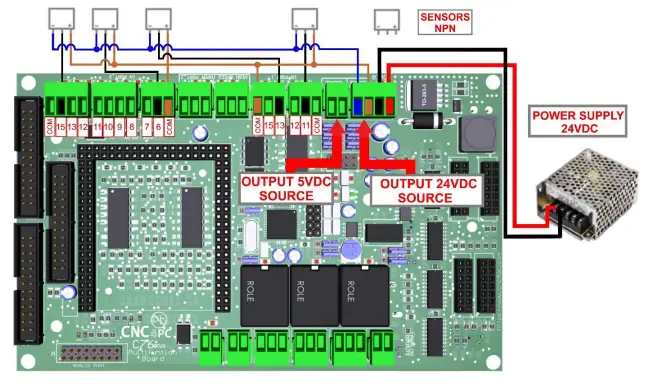
-Connection with the terminal of output source of the 5VDC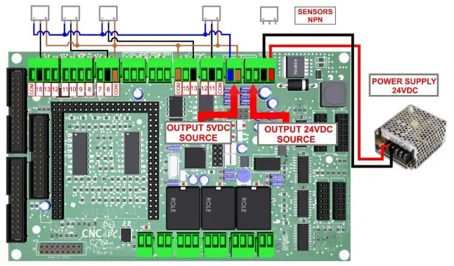 LED INDICATOR
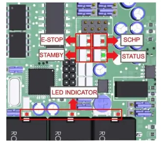
- The standby LED lights indicate that the system is ready but disabled. When Status LED, (Green LED) lights, it indicates that the system is enabled.
- There are 4 possible error sources: a driver fault, E-STOP error, SCHP error or VFD alarm. A LED will light close to the source of the fault.

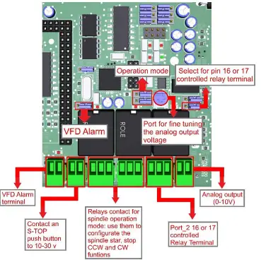
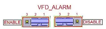
VFD Connection and configuration jumper
- The VFD Alarm monitoring feature can be enabled or disabled:


- The VFD Alarm will trigger when the contacts are open and the VFD Alarm is enabled.
For the Variable speed control go to
For Configure the control software go to
For Replacing Potentiometer go to
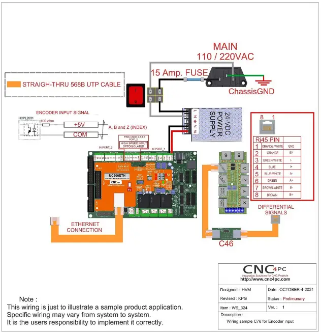
UC300ETH MOTHERBOARD
WIRING SAMPLE ENCODER
DIMENSIONS 
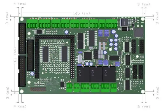
- All dimensions are in Millimeters.
Fixing holes (4mm)
Disclaimer:
- Use caution. CNC machines can be dangerous machines. Neither DUNCAN USA, LLC nor Arturo Duncan is liable for any accidents resulting from the improper use of these devices. This product is not a fail-safe device and it should not be used in life support systems or in other devices where its failure or possible erratic operation could cause property damage, bodily injury, or loss of life.


