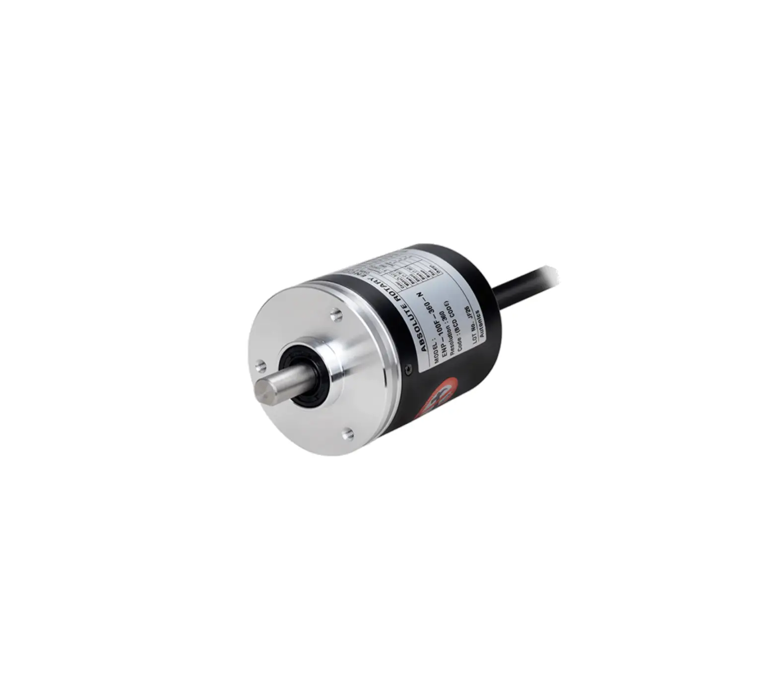
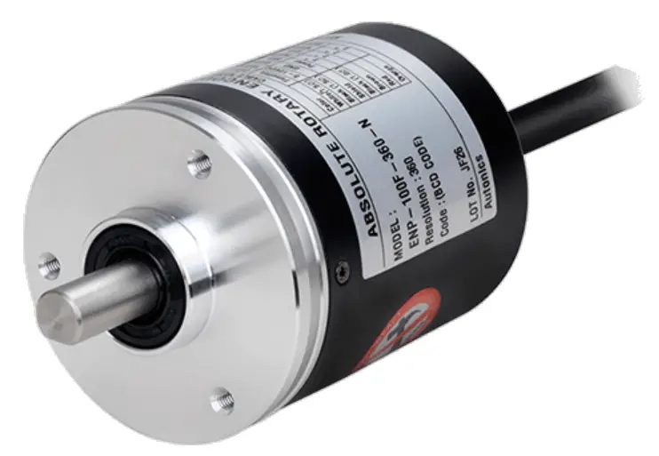
Autonics ENP Series 60mm Diameter Absolute Singe Turn Rotary Encoders
Thank you for choosing our Autonics product.
Read and understand the instruction manual and manual thoroughly before using the product.
For your safety, read and follow the below safety considerations before using.
For your safety, read and follow the considerations written in the instruction manual, other manuals and Autonics website.
Keep this instruction manual in a place where you can find easily.
The specifications, dimensions, etc. are subject to change without notice for product improvement. Some models may be discontinued without notice.
Follow Autonics website for the latest information.
Safety Considerations
- Observe all ‘Safety Considerations’ for safe and proper operation to avoid hazards.
 symbol indicates caution due to special circumstances in which hazards may occur.
![]() Warning Failure to follow instructions may result in serious injury or death
Warning Failure to follow instructions may result in serious injury or death
- Fail-safe device must be installed when using the unit with machinery that may cause serious injury or substantial economic loss. (e.g. nuclear power control, medical equipment, ships, vehicles, railways, aircraft, combustion apparatus, safety equipment, crime / disaster prevention devices, etc.)
Failure to follow this instruction may result in personal injury, economic loss or fire. - Do not use the unit in the place where flammable / explosive / corrosive gas, high humidity, direct sunlight, radiant heat, vibration, impact or salinity may be present.
Failure to follow this instruction may result in explosion or fire. - Install on a device panel to use.
Failure to follow this instruction may result in fire. - Do not connect, repair, or inspect the unit while connected to a power source.
Failure to follow this instruction may result in fire. - Check ‘Connections’ before wiring.
Failure to follow this instruction may result in fire. - Do not disassemble or modify the unit.
Failure to follow this instruction may result in fire
![]() Caution Failure to follow instructions may result in injury or product damage.
Caution Failure to follow instructions may result in injury or product damage.
- Use the unit within the rated specifications.
Failure to follow this instruction may result in fire or product damage. - Do not short the load.
Failure to follow this instruction may result in fire. - Do not use the unit near the place where there is the equipment which generates strong magnetic force or high frequency noise and strong alkaline, strong acidic exists.
Failure to follow this instruction may result in product damage.
Cautions during Use
- Follow instructions in ‘Cautions during Use’. Otherwise, It may cause unexpected accidents.
- 5 VDC⎓, 12 – 24 VDC⎓ power supply should be insulated and limited voltage / current or Class 2, SELV power supply device.
- For using the unit with the equipment which generates noise (switching regulator, inverter, servo motor, etc.), ground the shield wire to the F.G. terminal.
- Ground the shield wire to the F.G. terminal.
- When supplying power with SMPS, ground the F.G. terminal and connect the noise canceling capacitor between the 0 V and F.G. terminals.
- Wire as short as possible and keep away from high voltage lines or power lines, to prevent inductive noise.
- Check the wire type and response frequency when extending wire because of
distortion of waveform or residual voltage increment etc. by line resistance or capacity between lines. - This unit may be used in the following environments.
- Indoors (in the environment condition rated in ‘Specifications’)
- Altitude max. 2,000 m
- Pollution degree 2
- Installation category II
Cautions during Installation
- Install the unit correctly with the usage environment, location, and the designated specifications.
- Do not load overweight on the shaft.
- Do not put strong impact when insert a coupling into shaft.
Failure to follow this instruction may result in product damage. - When fixing the product or coupling with a wrench, tighten under 0.15 N m.
- If the coupling error (parallel misalignment, angular misalignment) between the shaft increases while installation, the life cycle of the coupling and the encoder can be shorten.
- Do not apply tensile strength over 30 N to the cable.
Ordering Information
This is only for reference, the actual prodcut does not support all combinations.
For selecting the specified model, follow the Autonics website.
❶ Output type
0: Negative logic
1: Positive logic
❷ Power supply
0: 5 VDC⎓ ±5%
1: 12 – 24 VDC⎓ ±5%
❸ Rotating direction
F: Increase output when the rotating direction is clockwise base on facing the shaft
R: Increase output when the rotating direction is counter-clockwise base on facing the shaft
❹ Resolution
Number: Refer to resolution in ‘Output Phase / Output Angle’
❺ Control output
N: NPN open collector output
P: PNP open collector output

Product Components
- Product
- Instruction manual
- Bolt × 4
- Coupling × 1
- Bracket × 2
Connections
- Unused wires must be insulated.
- The metal case and shield cable of encoders must be grounded (F.G.).
- F.G. (Frame Ground) must be grounded separately.
- Since exclusive driver IC is used for output circuit, be aware of short circuits when wiring each output wires.
- N·C: not connected
■ 6 / 8 / 12 / 16 / 24 division
| Color | Function | Refer |
| White | +V | Power (F.G. :signal shield) |
| Black | GND | |
| Shield | F.G. | |
| Black | TP1 | |
| Brown | 20 | |
| Red | 21 | |
| Orange | 22 | |
| Yellow | 23 | |
| Green | 20 × 10 | |
| Blue | 21 × 10 | |
| Purple | N·C | |
| Gray | TP2 | |
| White | EP | |
| Shield | F.G. | Signal shield |
■ 360 division
| Color | Function | Refer |
| White | +V | Power (F.G. :signal shield) |
| Black | GND | |
| Shield | F.G. | |
| Black | 20 | |
| Brown | 21 | |
| Red | 22 | |
| Orange | 23 | |
| Yellow | 20 × 10 | |
| Green | 21 × 10 | |
| Blue | 22 × 10 | |
| Purple | 23 × 10 | |
| Gray | 20 × 102 | |
| White | 21 × 102 | |
| Shield | F.G. | Signal shield |
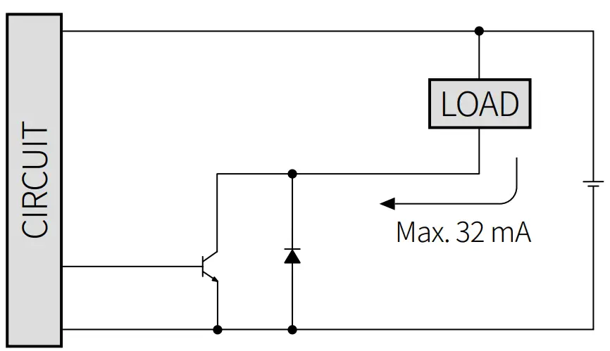
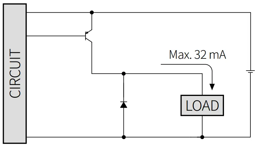
Inner Circuit
- The output circuit is identical for each output bit.
- Be aware of circuit break in case of overload or short beyond the specifications.
NPN open collector output
PNP open collector output
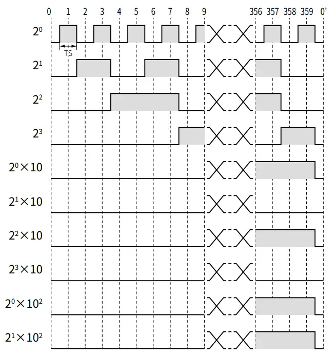
Output Waveform
- Following waveform is based on the positive logic.
(In case of negative logic, the waveform is opposite to corresponding waveform.)
Specifications
| Model | ENP-1□□□-□-N | ENP-1□□□-□-P |
| Resolution 01) | ≤ 360 division | |
| Output code | BCD code | |
| Control output | NPN open collector output | PNP open collector output |
| Inflow current | ≤ 32 mA | – |
| Residual voltage | ≤ 1 VDC⎓ | – |
| Outflow current | – | ≤ 32 mA |
| Output voltage | – | ≥ (power supply – 1.5) VDC⎓ |
| Response speed 02) | TON ≤ 800 nsec, TOFF ≤ 800 nsec | |
| Max. response freq. | 20 kHz | |
| Max. allowable revolution 03) | 3,600 rpm | |
| Starting torque | ≤ 0.05 N m | |
| Inertia moment | ≤ 300 g·cm2 (3 × 10⁻⁵ kg·m2) | |
| Allowable shaft load | Radial: 10 kgf, Thrust: 2.5 kgf | |
| Unit weight (packaged) | ≈ 400 g (≈ 478 g) | |
| Approval | EAC | |
- Refer to resolution in ‘Output Phase / Output Angle’.
- Based on cable length: 1 m, I sink = 32 mA
- Select resolution to satisfy Max. allowable revolution ≥ Max. response revolution [max. response revolution (rpm) = max. response frequency/resolution × 60 sec]
| Power supply | 5 VDC⎓ ± 5% (ripple P-P: ≤ 5%) / 12 – 24 VDC⎓ ± 5% (ripple P-P: ≤ 5%) model |
| Current consumption | ≤ 100 mA (no load) |
| Insulation resistance | Between all terminals and case: ≥ 100 MΩ (500 VDC⎓ megger) |
| Dielectric strength | Between all terminals and case: 750 VAC⎓ 50 / 60 Hz for 1 minute |
| Vibration | 1 mm double amplitude at frequency 10 to 55 Hz (for 1 minute) in each X, Y, Z direction for 2 hours |
| Shock | ≲ 75 G |
| Ambient temp. | -10 to 70 ℃, storage: -25 to 85 ℃ (no freezing or condensation) |
| Ambient humi. | 35 to 85%RH, storage: 35 to 90%RH (no freezing or condensation) |
| Protection rating | IP50 (IEC standard) |
| Connection | Axial cable type |
| Cable spec. | Ø 8 mm, 12-wire, 1 m, double shield cable |
| Wire spec. | AWG24 (0.08 mm, 40-core), insulator diameter – power wire: Ø 1.5 mm, signal wire: Ø 1 mm |
Output Phase / Output Angle
- TP = Timing Pulse
- TS = Signal Pulse
- EP = Even Parity
| Resolution | BCD Code |
| 360 | TS: 1° ±30′ (10 bit) |
| 24 | TP1: 8° ±30′ (2 bit) TP2: 3° ±30′ (2 bit) TS: 11° ±30′ (7 bit) EP: 15° ±30′ (1 bit) |
| 16 | TP1: 2° ±30′ (2 bit) TP2: 11.25° ±30′ (2 bit) TS: 19.5° ±30′ (6 bit) EP: 22.5° ±30′ (1 bit) |
| 12 | TP1: 3° ±30′ (2 bit) TP2: 15° ±30′ (2 bit) TS: 26° ±30′ (6 bit) EP: 30° ±30′ (1 bit) |
| 8 | TP1: 39° ±30′ (2 bit) TP2: 15° ±30′ (2 bit) TS: 42° ±30′ (5 bit) EP: 45° ±30′ (1 bit) |
| 6 | TP1: 53° ±30′ (2 bit) TP2: 15° ±30′ (2 bit) TS: 56° ±30′ (4 bit) EP: 60° ±30′ (1 bit) |
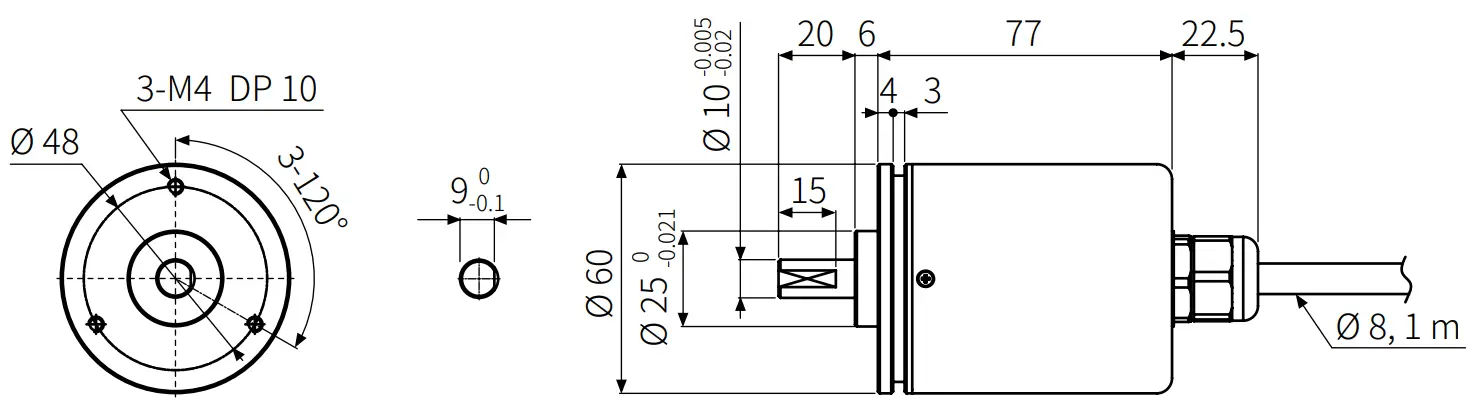
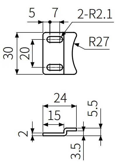
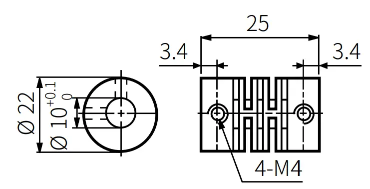
Dimensions
- Unit: mm, For the detailed drawings, follow the Autonics website.

- Bracket

- Coupling

- Parallel misalignment: ≤ 0.25 mm
- Angular misalignment: ≤ 5°
- End-play: ≤ 0.5 mm
Customer Support
18, Bansong-ro 513Beon-gil, Haeundae-gu, Busan, Republic of Korea, 48002
www.autonics.com | +82-2-2048-1577 | [email protected]