![]()
E28-2G4T12S User Manual
SX1280 2.4GHz TTL LoRa Module
Product Overview
Brief Introduction
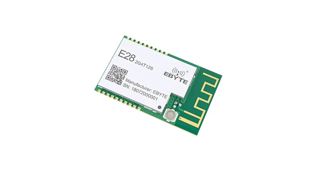
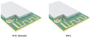
E28-2G4T12S is an UART module based on SEMTECH SX1280, it adopts transparent transmission and works at 2.4GHz band. It adopts LoRa, FLRC and GFSK modulations. It features SMD packing with both IPX and PCB antenna interfaces, and its TTL output is 3.3V.
The LoRa direct sequence spread spectrum (DSSS) enables longer communication range and better anti-interference ability. The forward error correction (FEC) algorism enables better coding efficiency and error correction ability. The module will proactively correct the interfered data packets when sudden interference occurs, which significantly improves the communication range and reliability.
The module features data encryption and compression. The data transmitted in air features randomness, the data encryption algorism makes data interception meaningless, meanwhile, the data compression function could shorten the transmission duration and reduce the probability of data interference, thus improves the reliability and transmission efficiency.
Features
- Support various modulation such as GFSK Mode,FLRC Mode,LoRa Mode;
- Supporting high-speed continuous transmission, data without subcontracting;
- Support RSSI for evaluating signal quality ;
- Support fixed transmission/broadcast/monitoring ;
- Communication distance tested is up to 3km in ideal condition; ;
- Maximum transmitting power of 12dBm, Software adjustable ;
- Support the global license-free ISM 2.4GHz ;
- Support air data rate of 1kbps~2Mbps;
- Low power consumption for battery supplied applications ;
- Support 2.3V~5.5V power supply, power supply over 5.5V can guarantee the best performance ;
- Industrial grade standard design, support -40 ~ 85 °C for working over a long time ;
- PCB and IPEX antenna optional, good for secondary and embedded development.
Application
- Smart Home and Industrial Sensors;
- Security system, location System
- Wireless remote control; UAV;
- Wireless Game Remote Controller
- Health care products ;
- Wireless voice, wireless headset;
- Automotive industry applications.
Technical Parameters
Limit parameter
| Main parameter | Performance | Note | |
| Min | Max | ||
| Voltage supply [V] | 0 | 5.5 | Voltage over 5.5V will cause permanent damage to module |
| Blocking power [dBm] | – | 10 | Chances of burn is slim when modules are used in short distance |
| Operating temperature [℃] | -40 | 85 | – |
Operating parameter
| Main parameter | Performance | Note | |||
| Min | Typ | Max | |||
| Voltage supply [V] | 2.3 | 5.0 | 5.5 | ?5.0V ensures output power | |
| Communication level [V] | 3.3 | For 5V TTL, it may be at risk of burning down | |||
| Operating temperature [°C] | -40 | – | +85 | – | |
| Frequency [MHz] | 2400 | – | 2500 | ISM band | |
| Power consumption | Transmitting current [mA] | 46 | Instant power consumption | ||
| Receiving current [mA] | 20 | ||||
| Turn-off current [PM | 8 | Software is shut down | |||
| Transmitting power [dBm] | 11.5 | 12.0 | 13.5 | ||
| Receiving sensitivity [dBm | -130 | -132 | -134 | Air data rate: 1.0kbps | |
| Air data rate (bps) | I k | lk | 2M | Defined by user via programming | |
| Main parameter | Description | Note |
| Distance | 3000m | Test condition: clear and open area, antenna gain: 5dBi , antenna height: 2.5m, air data rate: I kbps |
| FIFO | 121 Btye | Max. Transmitting length per packet |
| 221 Btye | Continuous transmission mode | |
| Modulation | GFSK | |
| LoRa | ||
| FLRC | ||
| Interface | UART | TTL |
| Package | SMD | |
| Connector | I.27nun | |
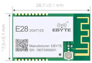
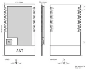
| Size | 17.5*28.7mm | |
| Antenna | IPEX/PCB | 5012 Impedance |
Dimension and Pin Defintion
| Pin No. | Pin Name | Pin Direction | Function |
| 1 | GND | Ground | Ground |
| 2 | NC | Disconnected | |
| 3 | M0 | Input | M2, M1 and M0 jointly decide the 8 operation modes. (cannot be floated, can be grounded if not used) |
| 4 | M1 | Input | M2, M1 and M0 jointly decide the 8 operation modes. (cannot be floated, can be grounded if not used) |
| 5 | M2 | Input | M2, M1 and M0 jointly decide the 8 operation modes. (cannot be floated, can be grounded if not used) |
| 6 | RXD | Input | TTL serial input, connected to external TXD output pin. Can be configured as open-drain or pull-up input, please refer to Parameter Configuration. |
| 7 | TXD | Output | TTL serial output, connected to external RXD input pin Can be configured open-drain or push-pull output, please refer to Parameter Configuration. |
| 8 | AUX | Output | Used to indicate the module operation status, when user wakes up the external MCU,it outputs low level during initialization after power on and self-check, can be configured as open-drain output or push-pull output, please refer to Parameter Configuration. (can be floated) |
| 9 | VCC | Module power source positive reference. Voltage range: 2.3 ~ 5.5V DC | |
| 10~11 | GND | Ground | Ground |
| 12~19 | NC | Disconnected | |
| 20 | GND | Ground | Ground |
Recommended Connection Diagram
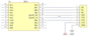
| No. | Brief description for module-MCU connection (STM8L MCU as example) |
| 1 | The wireless UART module adopts TTL level, please connect to MCU with TTL level. |
| 2 | For some 5V MCU, 4~10K pull-up resistor may need to be added at the TXD and AUX pins of the module. |
Functional Description
Fixed Transmission

Broadcast
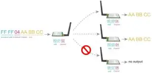
Broadcast Address
- i.e.: set the address of module A as 0xFFFF or 0x0000 and channel as 0x04.
- When set A as transmitter (same mode, transparent transmission on), all modules with channel 0x04 will receive broadcast data.
Monitor Address
- i.,e.: set the address of module A as 0xFFFF or 0x0000 and channel as 0x04.
- When set A as receiver, it will receive the data transmitted by modules with channel 0x04.
Module Reset
- When the module is powered on, the AUX output will go to a low level immediately, the module conducts hardware self-check and sets the operating mode on the basis of the user parameters (M0 M1). During the process, the AUX level remains low. After the process completed, the AUX outputs high a level and starts to work as per the operating mode indicated by the combined state of M1 and M0. The user needs to wait until the AUX rising edge is high, indicating the module is ready for normal work.
AUX Description
- AUX Pin can be used as indication for wireless send & receive buffer and self-check. It can indicate whether there is data that is yet to send via wireless or whether all wireless data has been sent through UART, or whether the module is still in the process of self-check initialization.
Indication of serial output
- Used to wake up the external MCU (note: AUX indicates no delay under continuous mode)

Indication of wireless transmission
- Under sub-packet transmission mode, the internal buffer size is determined by the sub-packet size, if the packet length is 221 bytes, then the buffer size will be 2048 bytes, when AUX=1, user could continuously initiate transmitting of no more than 2048 bytes.
- Under continuous transmission mode, AUX=1 means the module is busy, but it is not applicable for waking up external MCU, because the data transmission is very quick under continuous transmission mode.
- AUX=1 means all serial data is transmitted through RF, and the module is at idle state.
![]()
Module in configuration process
- Only occurs when resetting or when exiting sleep mode

Operation Modes
The module has 4 operation modes, which are determined accordingly by pins M0, M1. Please refer to below instructions:
| Mode (0-3) | M2 | Ml | MO | Introduction | Remarks |
| 0 -Transmission Mode | 1 | 0 | 0 | Serial port on, RF on, continuous transparent transmission | The air data rate can be manually configured and automatically adjusted along with baud rate values ; the baud rates on both sides must be the same under continuous transmission mode |
| 1- RSSI Mode | 1 | 0 | I | Serial port on, RF on, RSSI on | The module outputs RSSI value through serial port every 100ms |
| 2- Ranging Mode | I | I | 0 | Reserved | – |
| 3- Configuration Mode | I | I | I | Serial port on , RF off, parameter configuration | Baud rate is fixed as 9600 8N1 |
| 4- Low pm\ cr | 0 | x | x | lowest power consumption in low power mode | When M2 is set high, it is in normal working condition. when M2 is set low, it is in low power mode |
Mode Switch
- User could determine the module operation mode through the combination of high-low level of M2, M1 and M0. Mode switch can be controlled through the GPIO of the MCU.
- When M2, M1 and M0 changed and the module is in idle state (AUX at high level), it can starts to work normally under new mode, if serial data not transmitted completely, it will enter new mode after all data is transmitted; if the module receives data and send out through serial port, the module will enter new mode after the data is transmitted completely; so mode switch will only be valid when AUX outputs 1, or switch will be delayed.
- i.e.: under mode 2 or mode 4, when user inputs large amount of data continuously and conducts mode switch, the mode switch is invalid; the module will conduct new mode check after all data is transmitted; so, users are recommended to check the AUX pin status and conduct mode switch 2ms later when AUX outputs high level.
- When the module enters configuration mode from other modes, it will enter sleep mode when all data is processed completely (both TX and RX). This feature can be used for quick sleep to save energy; i.e.: the transmitter works under mode 0 and the user send serial data“12345”, then the user does not need to wait till the AUX enters idle state (high level) and directly switches to sleep mode and put the user main MCU into sleep mode, the module will automatically enter sleep mode 1ms later when all data is processed so as to save the MCU working time and lower energy consumption.
- Similarly, this feature can be utilized for any mode switch, the module will enter new mode automatically within 1ms when current even is processed completely, which saves the user’s efforts in checking AUX status and enables quick mode switch; for example, when switching from transmitting mode to receiving mode, the user MCU could enter sleep mode before mode switch, mode switch can be made by acquiring AUX change with external interrupt function.
- This operation is very flexible and efficient, it is designed based on convenient MCU operation, and it could ease the operation load of the entire system and increase the operation efficiency and lower the energy consumption.
Transmission Mode (Mode 0)
Under this mode, transparent transmission is available, that means the data transmitted from the transmitter will be received by the receiver in the original format. Under normal mode, the two sides could communicate with each other normally based on same air data rate, address and channel; under continuous transmission mode, the baud rates on both sides must be the same, it supports large file continuous transmission under baud rate from 1200bps ~ 115200bps.
RSSI Mode (Mode 1)
Under this mode, the module will output current RSSI value of 2.4GHz signal every 100ms so as to check the channel quality, the value is in HEX compliment format.
Ranging Mode (Mode 2)
(Reserved)
Sleep Mode (Mode 3)
Under this mode, Baud rate is fixed as 9600 8N1
Command Format
Under configuration mode (Mode 3:M0=1, M1=1, M2 =1), the supported parameters are as below
(Only support 9600 and 8N1 format when setting)
| No. | Command Format | Description |
| 1 | C0 + working parameters | C0 + 5 bytes working parameters are sent in hexadecimal format. 6 bytes in total and must be sent in succession. (Save the parameters when power-down) |
| 2 | C1+C1+C1 | Three C1 are sent in hexadecimal format. The module returns the saved parameters and must be sent in succession. |
| 3 | C2 + working parameters | C2 + 5 bytes working parameters are sent in hexadecimal format. 6 bytes in total and must be sent in succession. (Do not save the parameters when power-down) |
| 4 | C3+C3+C3 | Three C3 are sent in hexadecimal format. The module returns the version information and they must be sent in succession. |
| 5 | C4+C4+C4 | Three C4 are sent in hexadecimal format. The module will reset one time and they must be sent in succession. |
| 6 | E2+E2+E2 | Under transparent transmission mode, send three E2 in HEX format, the module will enter a 10s parameter configuration window period, user could configure the module parameters in the 10s with C0 command, 10s later, the module will work with the new parameters. |
| 7 | E3+E3+E3 | Under transparent transmission mode, send three E3 in HEX format, the module will enter a 10s parameter configuration window period, user could configure the module parameters in the 10s with 6-byte C0 command, 10s later, the module will work with the new parameters. |
Default parameter values
| Model | Default parameter values | ||||||
| Model | Frequency | Address | Channel | Air data rate | Baud rate | Parity | Transmitting power |
| E28-2G4T12S | 2.4GHz | 0x0000 | 0x13 | 10kbps | 9600 | 8N1 | 12dbm |
Reading Operating Parameters
| Command Format | Description |
| C1+C1+C1 | Under configuration,(M0=1,M1=1, M2=1), send command (HEX format) to the serial: C1 C1 C1, the module will return current parameter values, i.e.: C0 00 00 13 18 04. |
Reading Version Number
| Command Format | Description |
| C3+C3+C3 | In the configuration (M0=1,M1=1, M2=1), issue the command (HEX format) to the module serial port: C3 C3 C3, The module returns the current configuration parameters, for example: C3 00 47 10 0C 09 01 00; 00 28 indicates the module model (E28 series), 10 indicates the version number, 0C indicates the module power, and other parameters indicate other features of the module. |
Reset Command
| Command Format | Description |
| C4+C4+C4 | UIn the configuration (M0=1, M1=1, M2=1) issue the command (HEX format) to the module serial port: C4 C4 C4, the module will generate a reset; high level and the module starts to work normally. At this point, you can switch modes or initiate the next instruction. |
Parameter Configuration Commands
| No. | Item | I) ese ript ion | Remarks | |||
| 0 | HEAD | Fix OxCO or OxC2, it means this frame data is control command | Must be OxCO or OxC2 CO: Save the parameters when power-down C2: Do not save the parameters when power-down | |||
| 1 | ADDH | High address byte of module (the default OOH) | 00H-FFH | |||
| 2 | ADDL | Low address byte of module (the default OOH) | 00H-FFH | |||
| SPED | 7 | 6 | UART parity bit | The serial modes can be different on two sides. | ||
| 0 | 0 | 8N1 ( default) | ||||
| 0 | I | 801 | ||||
| I | 0 | 8E1 | ||||
| I | I | 8N1 (equal to 00) | ||||
| 5 | 4 | 3 | TTL UART baud rate (bps) | Under normal mode, the mode can be different; Under continuous transmission mode, the baud rate must be the same. | ||
| 0 | 0 | 0 | 1200 | |||
| 0 | 0 | 1 | 4800 | |||
| 0 | 1 | 0 | 9600 (default) | |||
| 0 | 1 | 1 | 19200 | |||
| I | 0 | 0 | 57600 | |||
| I | 0 | 1 | 115200 | |||
| I | 1 | 0 | 460800 | |||
| 3 | I | I | 1 | 921600 | ||
| I | 0 | Air data rate (bps) | Under non-continuous transmission mode, baud rate has nothing to do with RF parameters, and will not affect the transmission characteristics. Under continuous transmission mode, baud rate decides the air data rate. The high the baud rate, the faster the data transmission and the shorter communication range. The lower the air data rate, the longer the transmitting distance, the better anti-interference performance and the The air data rates on both sides must be the same. | |||
| 0 | 0 | 0 | Self-adaptive (continuous transmission) | |||
| 0 | 0 | 1 | lk | |||
| 0 | I | 0 | 5k | |||
| 0 | I | 1 | 10k (default) | |||
| I | 0 | 0 | 50k | |||
| I | 0 | 1 | 100k | |||
| I | 1 | 0 | 1M (FLRC) | |||
| I | I | 1 | 2M (FSK) | |||
| 4 | CHAN | Communication Channel | Default: Ox 18 | |||
| Normal mode: When air data rate is 1k, 5k or 10k, the formula to calculate channel is: 2400 + CHAN * 1MHz; when air data rate is 50k or 100k, the formula to calculate channel is: 2400 + CHAN * 2MHz; when air data rate is 1 M, the formula to calculate channel is: 2400 + CHAN * 3MHz; when air data rate is 2M, the formula to calculate channel is: 2400 + CHAN * 5MHz; | ||||||
| Continuous transmission mode: When baud rate is 1200, 9600 or 9200, the formula to calculate channel is: 2400 + CHAN *2MHz; when baud rate is 4800, 57600, 115200, the formula to calculate channel is: 2400 + CHAN *4MHz; when baud rate is 460800, 921600, the formula to calculate channel is: 2400 + CHAN *5MHz. | ||||||
| 5 | OPTION | 7 | Fixed transmission enabling bit (similar to Modbus) | Under fixed transmission mode, the first three bytes of each user’s data frame can be used as high/low address and channel. The module changes its address and channel when transmit. And it will revert to original setting after complete the process. It is transparent transmission under continuous mode. | |
| n | Transparent transmission mode | ||||
| 1 | Fixed transmission mode | ||||
| o | Reserved | ||||
| 5 | Reserved | ||||
| 4 | Measuring mode device type (reserved) | Under range measuring mode, the slave module address is determined by the ADDH and ADDL. | |||
| 0 | Slave (default) | ||||
| 1 | Master | ||||
| 3 | LBT switch | When LBT is turned on, channel quality will be checked before sending every data packet; if quality is good, data will be sent directly, if interference exists, data will be sent after interference disappears. It supports LBT only below air data rate 115200bps, LBT may affect the continuous transmission function. | |||
| 0 | Turn off LBT (default | ||||
| 1 | Turn on LBT | ||||
| 2 | 10 driving mode | This bit is used to the module internal pull-up resistor. It also increases the level’s adaptability in case of open drain. But in some cases, it may need an external pull-up resistor. | |||
| 1 | TXD, AUX push-pull output, RXD pull-up input | ||||
| 0 | TXD, AUX open-circuit output, RXD open-circuit input | ||||
| 1 | 0 | Transmission power (approximated) | The external power source must provide 100mA or above current output and ensure the power ripple is lower than 100mV. Low power transmission is not recommended due to its low power supply efficiency. | ||
| 0 | 0 | 12dBm (defult) | |||
| 0 | 1 | 10dBm | |||
| I | 0 | 7dBm | |||
| I | 1 | 4dBm | |||
| For example: The meaning of No.3 “SPED” byte: | |||||
| The binary bit of the byte | 7 | 4 | , 3 | i | 1 | 0 | ||
| C’ontigures by user | 0 | 0 | 0 | 1 | 0 | 0 | 1 | 1 |
| Meaning | UART parity bit:8N 1 | UART baud rate:9600 | Air data rate:10kbps | |||||
| Corresponding hexadecimal | 0 | 13 | ||||||
Hardware design
- It is recommended to use a DC stabilized power supply. The power supply ripple factor is as small as possible, and the module needs to be reliably grounded. ;
- Please pay attention to the correct connection of the positive and negative poles of the power supply. Reverse connection may cause permanent damage to the module ;
- Please check the power supply to ensure it is within the recommended voltage otherwise when it exceeds the maximum value the module will be permanently damaged ;
- Please check the stability of the power supply, the voltage can not be fluctuated frequently ;
- When designing the power supply circuit for the module, it is often recommended to reserve more than 30% of the margin, so the whole machine is beneficial for long-term stable operation;
- The module should be as far away as possible from the power supply, transformers, high-frequency wiring and other parts with large electromagnetic interference ;
- High-frequency digital routing, high-frequency analog routing, and power routing must be avoided under the module. If it is necessary to pass through the module, assume that the module is soldered to the Top Layer, and the copper is spread on the Top Layer of the module contact part(well grounded), it must be close to the digital part of the module and routed in the Bottom Layer ;
- Assuming the module is soldered or placed over the Top Layer, it is wrong to randomly route over the Bottom Layer or other layers, which will affect the module’s spurs and receiving sensitivity to varying degrees;
- It is assumed that there are devices with large electromagnetic interference around the module that will greatly affect the performance. It is recommended to keep them away from the module according to the strength of the interference. If necessary, appropriate isolation and shielding can be done ;
- Assume that there are traces with large electromagnetic interference (high-frequency digital, high-frequency analog, power traces) around the module that will greatly affect the performance of the module. It is recommended to stay away from the module according to the strength of the interference.If necessary, appropriate isolation and shielding can be done.
- If the communication line uses a 5V level, a 1k-5.1k resistor must be connected in series (not recommended, there is still a risk of damage) ;
- Try to stay away from some physical layers such as TTL protocol at 2.4GHz , for example: USB3.0;
- The mounting structure of antenna has a great influence on the performance of the module. It is necessary to ensure that the antenna is exposed, preferably vertically upward. When the module is mounted inside the case, use a good antenna extension cable to extend the antenna to the outside ;
- The antenna must not be installed inside the metal case, which will cause the transmission distance to be greatly weakened.
FAQ
The communication range is too short
- The communication distance will be affected when obstacle exists.
- Data lose rate will be affected by temperature, humidity and co-channel interference.
- The ground will absorb and reflect wireless radio wave, so the performance will be poor when testing near ground.
- Sea water has great ability in absorbing wireless radio wave, so performance will be poor when testing near the sea.
- The signal will be affected when the antenna is near metal object or put in a metal case.
- Power register was set incorrectly, air data rate is set as too high (the higher the air data rate, the shorter the distance).
- The power supply low voltage under room temperature is lower than 2.5V, the lower the voltage, the lower the
- transmitting power.
- Due to antenna quality or poor matching between antenna and module.
Module is easy to damage
- Please check the power supply source, ensure it is 2.0V~3.6V, voltage higher than 3.6V will damage the module.
- Please check the stability of power source, the voltage cannot fluctuate too much.
- Please make sure antistatic measure are taken when installing and using, high frequency devices have electrostatic susceptibility.
- Please ensure the humidity is within limited range, some parts are sensitive to humidity.
BER(Bit Error Rate) is high
- There are co-channel signal interference nearby, please be away from interference sources or modify frequency and channel to avoid interference;
- Poor power supply may cause messy code. Make sure that the power supply is reliable.
- The extension line and feeder quality are poor or too long, so the bit error rate is high.
Production Guidance
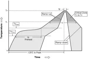
Reflow soldering temperature
| Profile Feature | Curve characteristics | Sn-Pb Assembly | Pb-Free Assembly |
| Solder Paste | Solder Paste | Sn63/Pb37 | Sn96.5/Ag3/Cu0.5 |
| Preheat Temperature min (Tsmin ) | Min preheating temp. | 100℃ | 150℃ |
| Preheat temperature max (Tsmax) | Max preheating temp. | 150℃ | 200℃ |
| Preheat Time (Tsmin to Tsmax)(ts) | Preheating time | 60-120 sec | 60-120 sec |
| Average ramp-up rate(Tsmax to Tp) | Average ramp-up rate | 3℃/second max | 3℃/second max |
| Liquidous Temperature (TL) | Liquid phase temp. | 183℃ | 217℃ |
| Time (tL )Maintained Above(TL ) | Time above liquid phase line | 60-90 sec | 30-90 sec |
| Peak temperature (Tp ) | Peak temperature | 220-235℃ | 230-250℃ |
| Average ramp-down rate (Tp to Tsmax ) | Average ramp-down rate | 6℃/second max | 6℃/second max |
Reflow soldering curve
| Type | IC | Frequency | Power | Distance | Size | Package | Interface |
| Hz | dBm | km | mm | ||||
| E28-2G4T12S | SX1280 | 2.4G | 12.5 | 3 | 17.5*28.7 | SMD | TTL |
| E28-2G4M27S | SX1280 | 2.4G | 27 | 8 | 15*26.5 | SMD | SPI |
| E28-2G4M20S | SX1280 | 2.4G | 20 | 6 | 15*26.5 | SMD | SPI |
| E28-2G4M12S | SX1280 | 2.4G | 12.5 | 3 | 25*14 | SMD | SPI |
Antenna Guidance
Antenna recommendation
Antenna plays an important role in the communication process. Inferior antennas often have a great impact on the communication system. Therefore, we recommend some antennas that support our wireless modules and have excellent performance and reasonable prices.
| Model | Type | Frequency | Gain | Size | Feeder | Interface | Feature |
| Hz | dBi | mm | cm | ||||
| TX2400-NP-5010 | FPC | 2.4G | 2 | 10×50 | – | IPEX | FPC antenna |
| TX2400-JZ-3 | Rubber | 2.4G | 2 | 30 | – | SMA-J | Straight antenna,ultra short |
| TX2400-JZ-5 | Rubber | 2.4G | 2 | 50 | – | SMA-J | Straight antenna,ultra short |
| TX2400-JW-5 | Rubber | 2.4G | 2 | 50 | – | SMA-J | Fixed bending antenna |
| TX2400-JK-11 | Rubber | 2.4G | 2.5 | 110 | – | SMA-J | Flexible antenna, omnidirectional |
| TX2400-JK-20 | Rubber | 2.4G | 3 | 200 | – | SMA-J | Flexible antenna, omnidirectional |
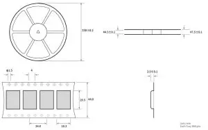
| TX2400-XPL-150 | Sucker | 2.4G | 3.5 | 150 | 150 | SMA-J | Small sucker antenna,high gain |
Antenna selection
Package for batch order
Revision history
| Version | Date | Description | Operator |
| 1 | 1/8/2018 | Initial Version | huaa |
| 1.1 | 4/16/2018 | Content added | huaa |
| 1.2 | 5/24/2018 | Content added | Huaa |
| 1.3 | 7/20/2018 | Name updated | Huaa |
| 1.4 | 3/12/2019 | Content added | Ray |
| 1.5 | 5/11/2020 | Parameter correction | du |
About us
Website: www.ebyte.com Sales: [email protected] Support: [email protected]
Tel: +86-28-61399028 Ext. 812 Fax: +86-28-64146160
Address: Innovation Center B333~D347, 4# XI-XIN road,High-tech district (west), Chengdu, Sichuan, China

Copyright ©2012–2019, Chengdu Ebyte Electronic Technology Co., Ltd.


