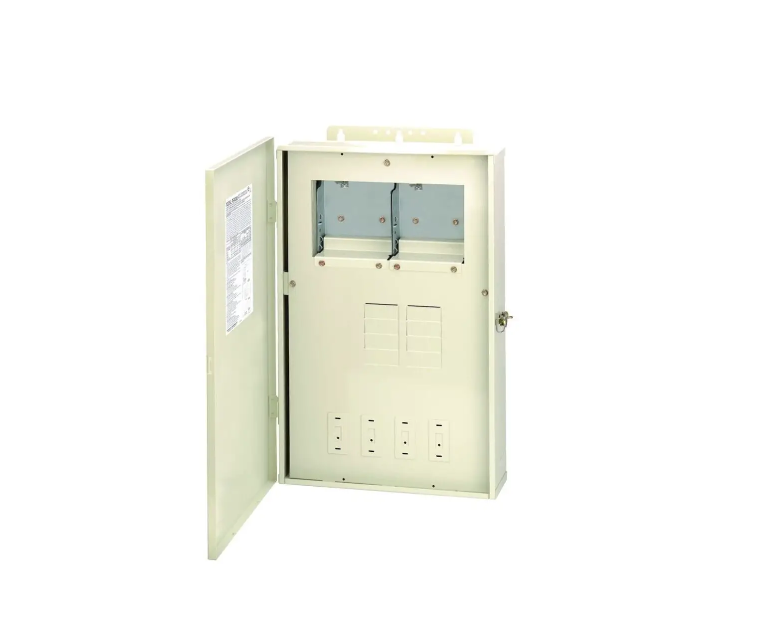
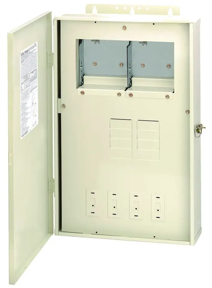
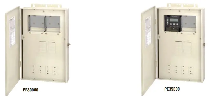
INTERMATIC PE35300 80A Load Center with P1353ME Mechanism
PRODUCT DESCRIPTION
This system can be used as a load center only, or add mechanisms or wiring devices for complete control systems.
FEATURES
- 80 A 8-position breaker base
- 3-SPST mechanism (P1353ME) controls single and two-speed filter pumps, cleaner/booster pumps, and pool/spa landscape lighting
- Load center dead front has four knockouts for switches or GFCIs
- Transformer option provides low voltage for LED lights
- Wiring devices may be installed in these load centers with the use of Standoffs, sold separately
APPLICATIONS
- Distribution/Control Panel
- Motor Control
- Pump Control
TECHNICAL DATA
General
- Model Number PE35300
- Description 80 A Load Center with P1353ME Mechanism
- UPC Code 078275105331
- Brand Intermatic
- Country of Origin (Intermatic) CANADA
- Warranty Period 1-Year limited
Mechanical Specifications
- Number of Breaker Knockouts 8
- Enclosure Type Outdoor type 3R plastic
Dimensions
- Product Dimensions (H x W x D) in 22.875 x 14.875 x 4.75 in
- Knockout Dimensions Bottom (1) 1 1/8″ diameter hole, (6) 1/2″ – 3/4″, (3) 3/4″ – 1″
- Knockout Dimensions Back (1) 3/4″ – 1″
- Knockout Dimensions Left (2) 1/2″ – 3/4″
- Knockout Dimensions Right (1) 1 3/4″ x 2 3/4″
Load Ratings
- Tungsten Range(s) 5 A, 120/240 VAC, 50/60 Hz
- Motor 80 LRA @ 120 VAC, 50 Hz;80 LRA @ 240 VAC, 50 Hz;17 FLA @ 120 VAC, 50 Hz;17 FLA @ 240 VAC, 50 Hz;80 LRA @ 120 VAC, 60 Hz;80 LRA @ 240 VAC, 60 Hz;17 FLA @ 120 VAC, 60 Hz;17 FLA @ 240 VAC, 60 Hz
- Load Center Ratings 80 A;80 A, 208 VAC, Single Phase
- Auxiliary Switch 2 A, 24 VAC
- Resistive Load Ratings Ranges 17 A, 120/240 VAC, 50/60 Hz
- Motor Load Ratings Ranges 80 LRA, 17 FLA @ 120/240 VAC, 50/60 Hz
Electrical Specifications
- Number of Circuits 3
- Switch Type 3-SPST
- Number of Receptacle/Switch Knockouts 4
Packaging
- Shipping Weight (lbs) 24.21
- Unit Carton Dimensions (H x W x L) in 5.509 x 16.009 x 23.509 in
Standards and Certifications
- CSA Certification cCSAus
- California Proposition 65 DEHP

ACCESSORIES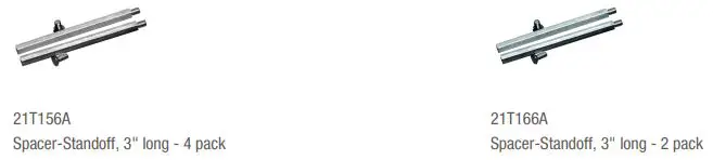
WARNING
Risk of Fire or Electric Shock
- Disconnect power at the circuit breaker(s) or disconnect switch(es) before installing or servicing.
- Installation and/or wiring must be in accordance with National Electrical Code (Article 680)/Canadian Electrical Code (Section 68) and local electrical code requirements and is subject to approval by the local inspection authority.
- Use #14 – #6 AWG COPPER conductors ONLY, rated 75° C min., for branch circuit and #14 – #2 AWG for main lugs and neutral main.
- For outdoor locations or wet locations (rain-tight), conduit hubs that comply with requirements of the UL514B (standard for fittings for conduit and outlet boxes) are to be used.
- Install only LISTED receptacle(s) and/or wiring device(s) inside the enclosure.
- The control panel is to be a minimum of 3m (in Canada) or 5ft (in USA) from the inside wall of the pool, spa, or pond, unless separated from the body of water by a fence, wall or other permanent barrier that will make the unit inaccessible to persons in the water.
- If this enclosure is used for direct conduit connection to a wet-niche or no-niche luminaire, one of the connection kits listed below in NOTE 6 must be used.
- When panel is outdoors, a LISTED rainproof cover must be installed over the wiring device in the side knockout.
- This control should not be connected to any equipment which would cause bodily injury or property damage should it be activated unexpectedly.
- Follow circuit breaker manufacturer’s installation instructions.
- Do not connect two or more power supplies in parallel.
- Replace front panel covering terminals before powering ON.
- KEEP DOOR CLOSED AT ALL TIMES when not servicing.
| SUITABLE LISTED BREAKERS | WIRING INFORMATION – COPPER CONDUCTORS ONLY | ||||||||||||||
| MANUFACTURER | CIRCUIT BREAKER | FILLER PLATE | WIRE SIZE 75˚C MIN INSULATION | SUPPLY CIRCUIT BREAKER RATING | TERMINAL TORQUEa | MAX MOTOR LOAD (CONTINUOUS DUTY) | GENERAL PURPOSE BRANCH CIRCUIT | ||||||||
| SINGLE | DOUBLE | TWIN | QUAD | GFCB | LINE AND NEUTRAL MAIN LUGS | NEUTRAL AND GROUND | |||||||||
| CUTLER-HAMMER MURRAY SIEMENS | BR MP-T QP | BR MP-T QP | BRD MH-T QT | BRD MH-T QT | GFCB MP-GT QPF | BRFP LX100FP QF3 | BREAKER RATING | MAX CURRENT CAPACITY | |||||||
| 120 V | 240 V | ||||||||||||||
| AWG | AMP | LB-IN | LB-IN | HP | HP | AMP | AMP | ||||||||
| SQUARE D | HOM | HOM | HOMT | HOMT | HOM | HOMFP | |||||||||
| 14 12 10 8 6 4 | 15
20 30 50b 65 80 | 35 35 35 40 45 45 | 20 20 20 25 35 35 | 1/2 1 1 1/2 2 — — | 1 2 3 5 — — | 15 20 30 40 60 — | 12 16 24 32 44 — | ||||||||
| GE (up to 40 A) | THQL | THQL | — | — | THQL-GF, GF1 | THFILLER | |||||||||
| NOTES: | |||||||||||||||
| 1. Any Intermatic T100M or ET100CM Series Time Switch, PF1000M Series Freeze Protection or | |||||||||||||||
| RC2000M Series Air Switch mechanisms, P1353ME mechanism, P4243ME mechanism, or P4043ME | |||||||||||||||
| mechanism may be installed in the bracket(s) provided or in the event an existing mechanism(s) | |||||||||||||||
| is replaced. The P5043ME can also be used in this panel in conjunction with a MultiWave Control | |||||||||||||||
NOTES: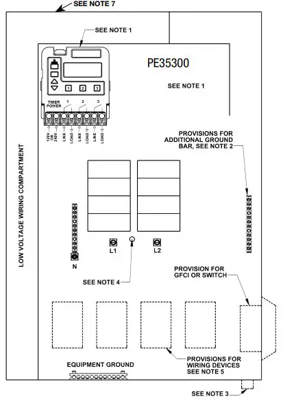
- Any Intermatic T100M or ET100CM Series Time Switch, PF1000M Series Freeze Protection or RC2000M Series Air Switch mechanisms, P1353ME mechanism, P4243ME mechanism, or P4043ME mechanism may be installed in the bracket(s) provided or in the event an existing mechanism(s) is replaced. The P5043ME can also be used in this panel in conjunction with a MultiWave Control System. If a filler plate is needed, contact factory.
- An additional ground bar may be installed in this control panel (order 130T1318A).
- If this control panel requires bonding, attach a LISTED bonding terminal of a suitable size using the mounting hole(s) provided on the bottom of the enclosure.
- When a circuit breaker is back-fed, 22T904A breaker hold-down kit must be used.
- A wiring device may be installed in this control panel (order 21T156A (4) standoffs for mounting).
- The following kits are available to connect underwater luminaires to this enclosure:
- 1/2” non-metallic – order 156PA13713A
- 3/4” non-metallic – order 156PA13714A
- 1” non-metallic – order 156PA13715A
- 1/2” metallic – order 156PA14336A
CONTACT RATINGS – EACH CIRCUIT, (P1353ME)
- 17 A Resistive, 120/240 VAC, 60 Hz
- 17 FLA, 80 LRA, 120/240 VAC, 60 Hz
- 5 A Tungsten, 120/240 VAC, 60 Hz
- Aux. Switch, 2 A, 24 VDC
EVENTS PER CIRCUIT: 3 ON/OFF Events Per Circuit
MEMORY RETENTION:
40-year retention for all programmed settings. 8-hour time retention.
P1353ME OPERATING INSTRUCTIONS
- Press PROG Key to cycle through menu options.
- Press UP and DOWN arrow keys to change program settings.
- Press ENTER key to save changes and exit programming mode.
- Press ON/OFF keys to manually turn devices ON or OFF. VALVE ACTUATOR SUPPLY: 24 V – 40 VA MAX.
3-CIRCUIT DIGITAL CONTROL RATINGS:
- CLOCK SOURCE VOLTAGE: 120/240 VAC, 60 Hz
- POWER CONSUMPTION: 6.0 W Max
- CONTACT CONFIGURATION: SPST – each circuit


