![]() 750 through 6000 Benchmark and Benchmark Platinum Boilers
750 through 6000 Benchmark and Benchmark Platinum Boilers
Instruction Manual
750 through 6000 Benchmark and Benchmark Platinum Boilers
Electrical Power Design Guide
Benchmark® and Benchmark Platinum Boilers
Models 750 through 6000 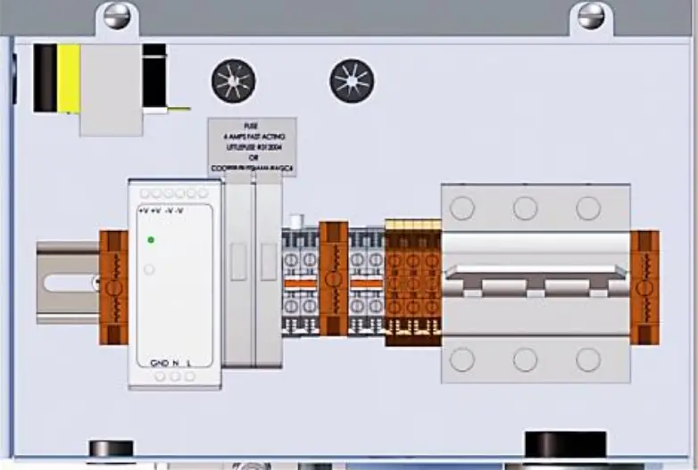
Other documents for this product include:
OMM-0127, GF-205-K BMK750K-3000K Installation-Startup KOREA
OMM-0128, GF-206-K BMK750K-3000K Operation- Maintenance KOREA
OMM-0136, GF-210 BMK750-6000 Platinum-Edge Installation-Startup
OMM-0137, GF-211 BMK750-6000 Platinum-Edge Operation-Service
OMM-0138, GF-212 BMK750-6000 Platinum-Edge Reference Manual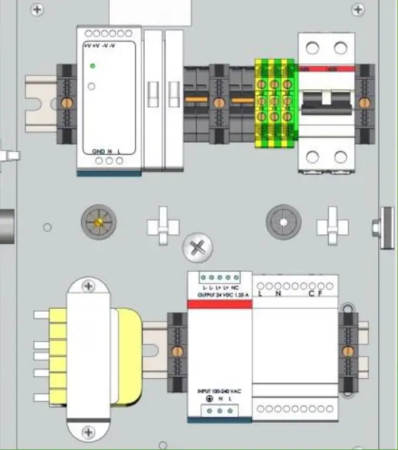 TAG-0019, GF-2070 Benchmark Boiler Application Guide
TAG-0022, GF-2050 Benchmark Vent & Combustion Air Guide
TAG-0047, GF-2030 Benchmark Gas Guide
Disclaimer
The information contained in this manual is subject to change without notice from AERCO International, Inc. AERCO makes no warranty of any kind with respect to this material, including, but not limited to, implied warranties of merchantability and fitness for a particular application. AERCO International isnot liable for errors appearing in this manual, not for incidental or consequential damages occurring in connection with the furnishing, performance, or use of these materials.
Heating and Hot Water Solutions
AERCO International, Inc. • 100 Oritani Drive • Blauvelt, NY 10913
USA: T: (845) 580-8000 • Toll Free: (800) 526-0288 • AERCO.com
Technical Support • (800) 526-0288 • Mon-Fri, 8 am – 5 pm EST
© 2020 AERCO
General
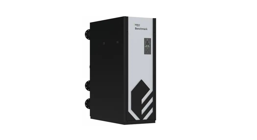
Benchmark (BMK) Gas Fired Boilers are fully factory wired packaged units which require simple external power wiring as part of the installation (Figure 1). This technical guide is intended to help designers provide electrical power wiring (line voltage) to Benchmark units. Control wiring details are provided in other publications, depending upon unit application. This document is intended only as a guide and therefore cannot include all possible alternatives or unit applications. In order to comply with all codes and authorities having jurisdiction, designers and installers must plan the electrical wiring carefully and execute the installation completely. Emergency shutoffs, fusible fire switches, break glass stations, and other electrical requirements should be considered and installed whenever necessary.
Boiler Electrical Requirements
Benchmark boilers are available with the following power options:
| BMK Model | Voltage | Phase | Amperage |
| BMK750 — 1000 Domestic | 120 V | 10 / 60 Hz | 15 |
| BMK750 — 1000 International | 220 V | 10 / 50-60 Hz | 20 |
| BMK1500 — 2000 Domestic | 120 V | 10 / 60 Hz | 20 |
| BMK1500 — 2000 International | 220 V | 10 / 50-60 Hz | 20 |
| BMK2500 – 3000 Domestic | 208 V | 30 / 60 Hz | 20 |
| 480 V | 30 / 60 Hz | 15 | |
| BMK2500 – 3000 International | 380-415 V | 30 / 50-60 Hz | 15 |
| BMK4000 – 5000N Domestic | 208 V | 30 / 60 Hz | 40 |
| 480 V | 30 / 60 Hz | 20 | |
| BMK4000 – 5000N International | 380-415 V | 30 / 50-60 Hz | 20 |
| BMK5000 – 6000 Domestic | 208 V | 30 / 60 Hz | 30 |
| 480 V | 30 / 60 Hz | 20 | |
| BMK5000 – 6000 Canada | 575 V | 30 / 60 Hz | 20 |
| BMK5000 – 6000 International | 380-415 V | 30 / 50-60 Hz | 20 |
Voltages lower than those specified in the table above will result in increased wear and premature failure of the blower motor. Wire size and type should be made per the National Electrical Code based on length and load.
For all Benchmark models, the power box for field wiring connections is located in the upper right corner behind the unit front panel. All copper wire must be connected to the power box.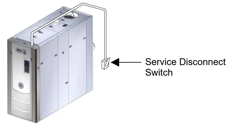
Figure 1: Service Disconnect Switch Typical Location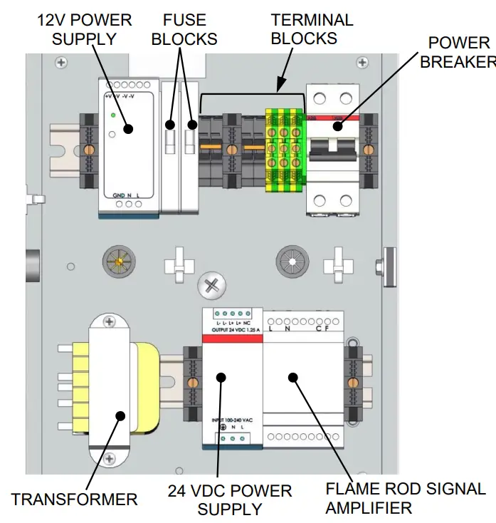 Figure 2a: Power Box Components, BMK750 & 1000 – DOMESTIC
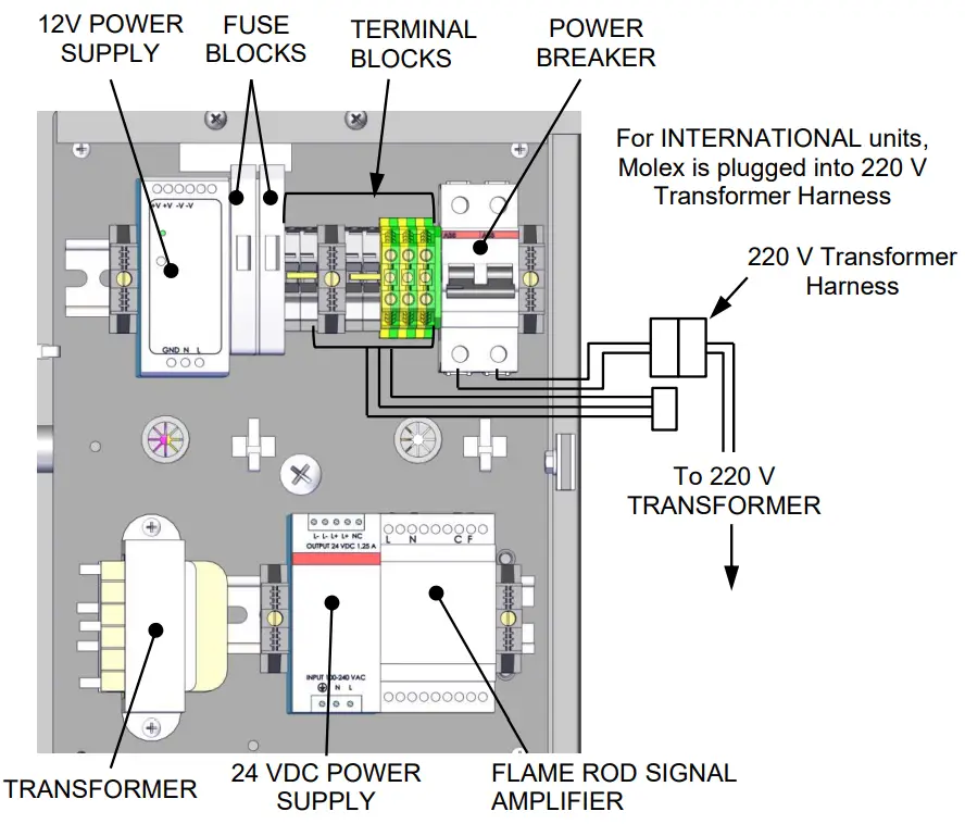
Figure 2a: Power Box Components, BMK750 & 1000 – INTERNATIONAL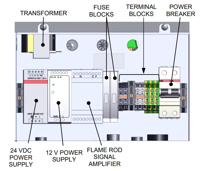
Figure 3a: Power Box Components, BMK1500 – 2000 – DOMESTIC 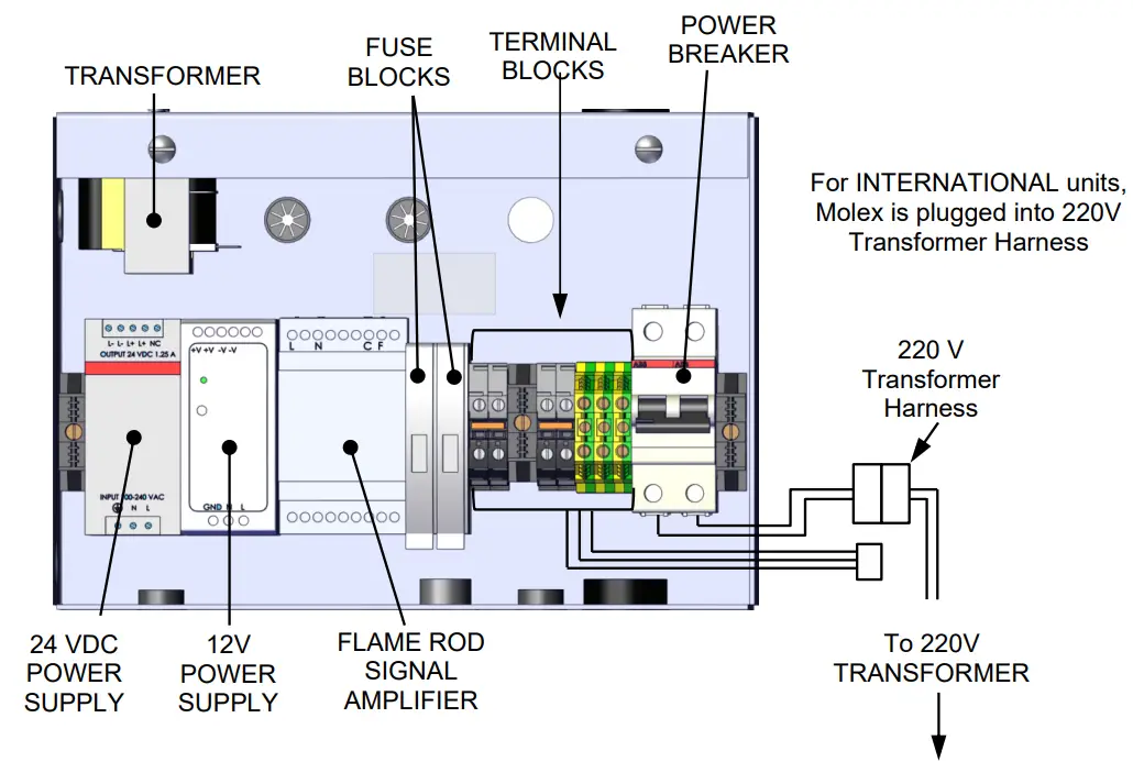 Figure 3b: Power Box Components, BMK1500 – 2000 – INTERNATIONAL
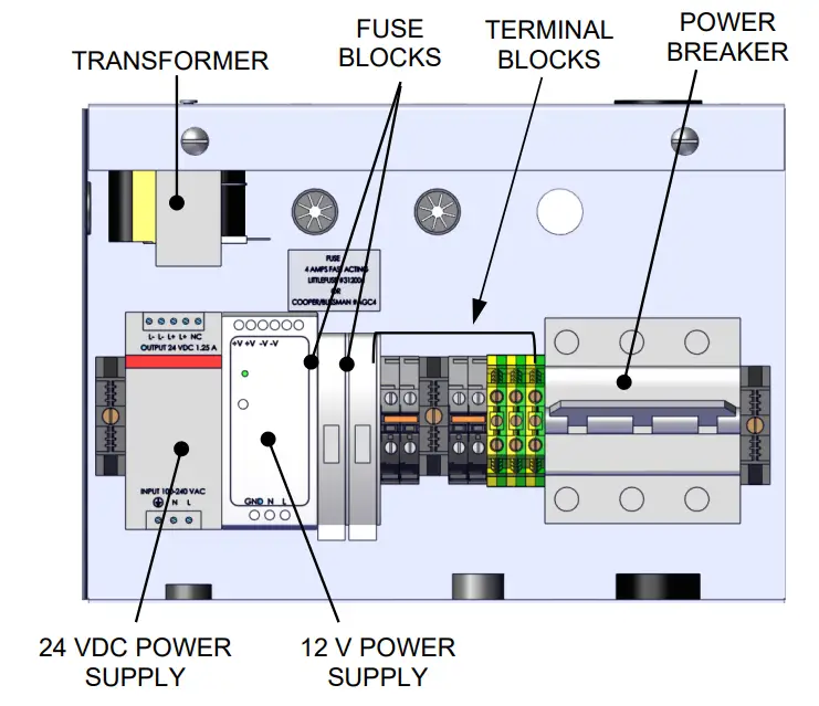 Figure 4a: Power Box Components, BMK2500 – 6000 – DOMESTIC
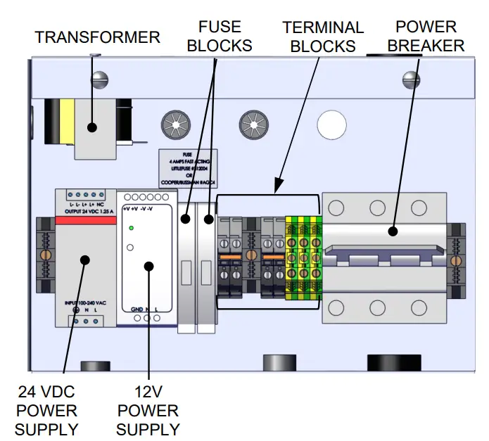
Figure 4b: Power Box Components, BMK2500 – 6000 – INTERNATIONAL
Provisions for Service
Designers must provide emergency shutoffs and other devices to satisfy electrical codes. It is also recommended to provide an electrical shutoff disconnect switch of suitable load carrying characteristics near each BMK boiler. No electrical boxes or field components should be mounted to the surface of the boiler or where they would interfere with the removal of the side or top panels for maintenance. The service disconnect switch should be mounted near the unit, as illustrated in Diagram 1. Wiring conduit, EMT, or other wiring paths should not be secured to the unit but supported externally. Electricians should be instructed as to where the wiring conduit should be located, such as away from the relief valve discharge, drains, etc. All electrical conduit and hardware should be installed so that it does not interfere with the removal of any covers, inhibit service or maintenance, or prevent access between the unit and walls or another unit.
Boiler Wiring
A dedicated protected circuit should be provided from the power source to the boiler. No other electrical devices should be permanently wired on the same circuit. The protected circuit and circuit breaker switch must be sized for the amperage values below. An emergency switch (electrical shutoff) must be wired in series with power to the unit. Connecting an emergency shutoff switch (E-stop) to the main power terminals of the boiler is the recommended and safest way to totally disable and un-power the unit. Use of the remote interlock, located on the I/O board, is not recommended since it does not cutoff power within the unit, it only disables it. Under no circumstance should the remote interlock of the BST Manager unit be used as an emergency switch for the plant.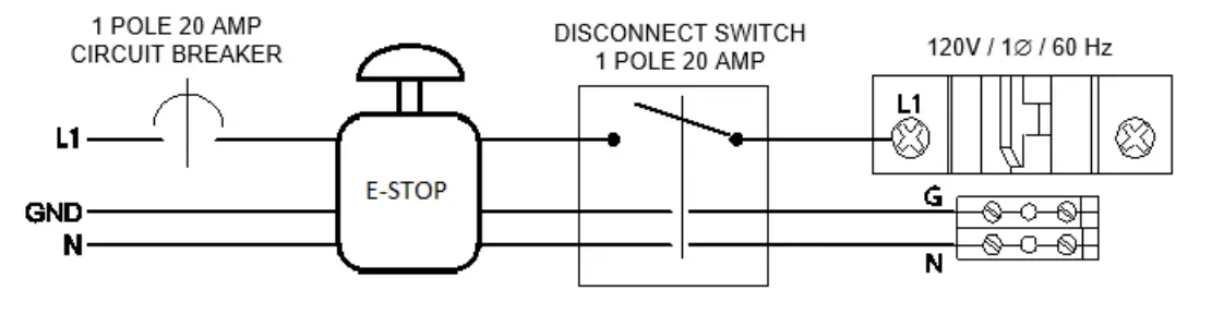
The following table lists the input power requirements for all Benchmark boilers, including the diagram number of each model’s corresponding schematic diagram:
| DOMESTIC UNITS | INTERNATIONAL UNITS | |||||||
| BMK Model | Diag. | Voltage/Phase/Frequency | Amps | Wires | Diag. | Voltage/Phase/Frequency | Amps | Wires |
| 750 — 1000 | la | 120V/ 10/60 Hz© | 15 A | 3 | lb | 220V / 1 Z / 50- 60 Hz | 20 A | 3 |
| 1500 — 2000 | 20 A | |||||||
| 2500/3000 | 2 | 208V / 30 / 60 Hz | 20 A | 5 4 4 | 3b | 380-415V / 3.Z / 50- 60 Hz | 15 A | 4 I |
| 3a | 480V / 30 / 60 Hz | 15 A | ||||||
| 4000/5000N | 7 | 208 V / 30 / 60 Hz | 40A | |||||
| 6a | 480V / 30 / 60 Hz | 20 A | 4 | 6b | 380-415V / 3Z / 50- 60 Hz | 20 A | 4 | |
| 5000/6000 | 4 | 208V / 30 / 60 Hz | 30A | 4 | ||||
| 5a | 480V or 575V / 3Z / 60 Hz | 20 A | 4 | 5b | 380-415V / 3Z / 50-60 Hz | 20 A | 4 | |
For applicable wiring connections, refer to the schematic diagrams below. 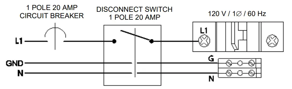
Diagram 1a – BMK750 – 2000: 120 V / 1ø / 60 Hz Wiring Schematic – 3 Wire – DOMESTIC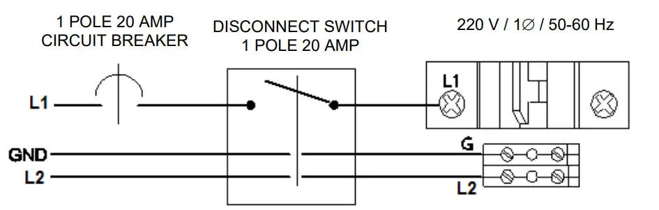 Diagram 1b – BMK750 – 2000: 220 V / 1ø / 50-60 Hz Wiring Schematic – 3 Wire – INTERNATIONAL
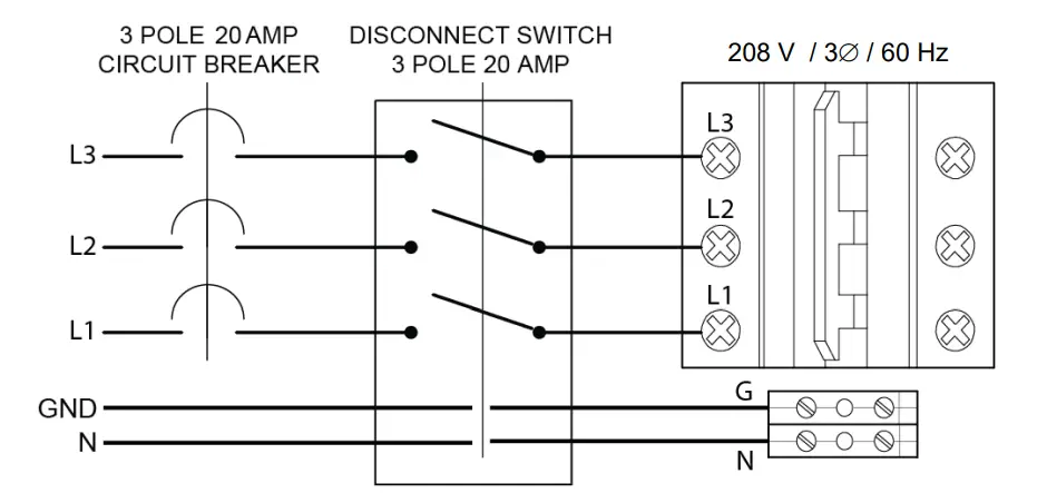 Diagram 2 – BMK2500/3000: 208 V / 3ø / 60 Hz Wiring Schematic- 5 Wire – DOMESTIC
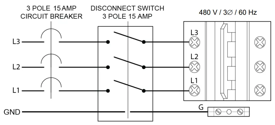 Diagram 3a – BMK2500-5000N: 480 V / 3ø / 60 Hz Wiring Schematic- 4 Wire – DOMESTIC
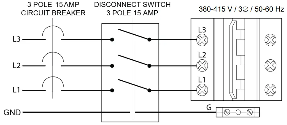
Diagram 3b- BMK2500-5000N: 380-415 V / 3ø / 50-60 Hz Wiring Schematic- 4 Wire – INTERNATIONAL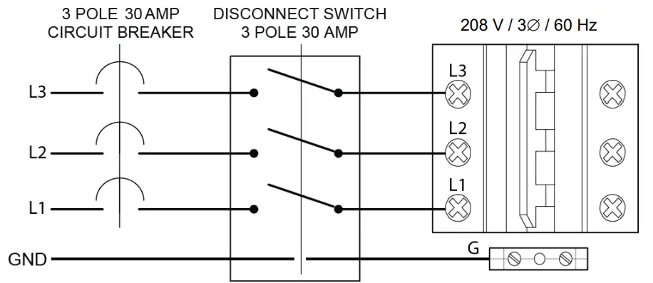 Diagram 4: BMK5000/6000: 208 V / 3ø / 60 Hz Wiring Schematic- 4 Wire – DOMESTIC
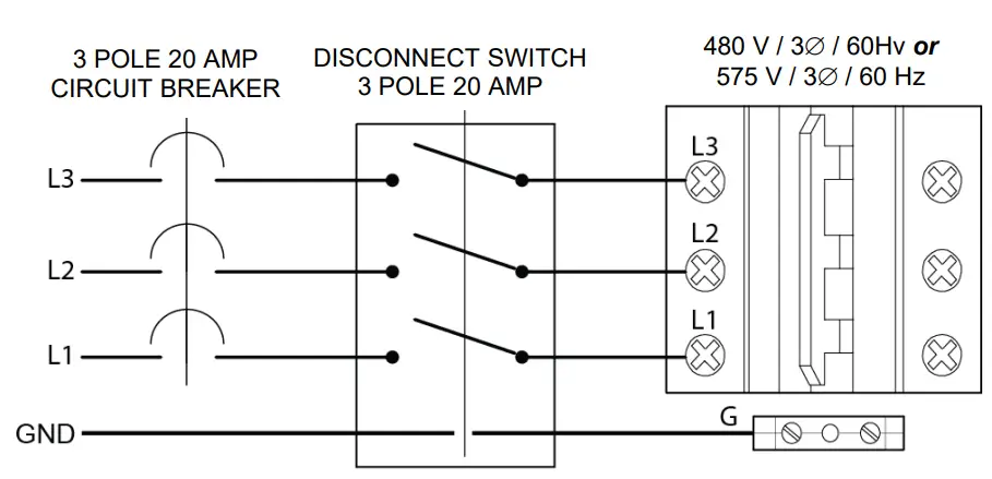 Diagram 5a: BMK5000/6000: 480 V or 575 V / 3ø / 60 Hz Wiring Schematic- 4 Wire – DOMESTIC
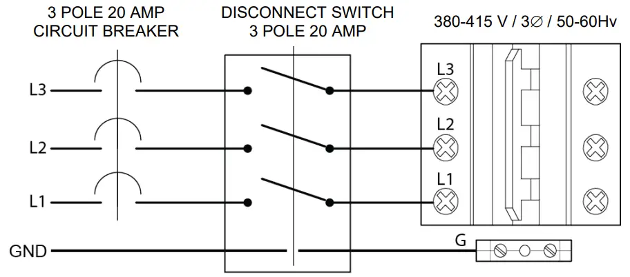 Diagram 5b: BMK5000/6000: 380-415 V / 3ø / 50-60 Hz Wiring Schematic- 4 Wire – INTERNATIONAL
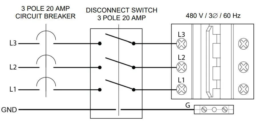
Diagram 6a – BMK4000-5000N: 480 V / 3ø / 60 Hz Wiring Schematic- 4 Wire – DOMESTIC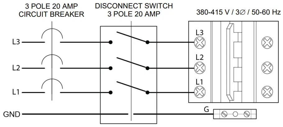 Diagram 6b- BMK4000-5000N: 380-415 V / 3ø/ 50-60 Hz Wiring Schematic- 4 Wire – DOMESTIC
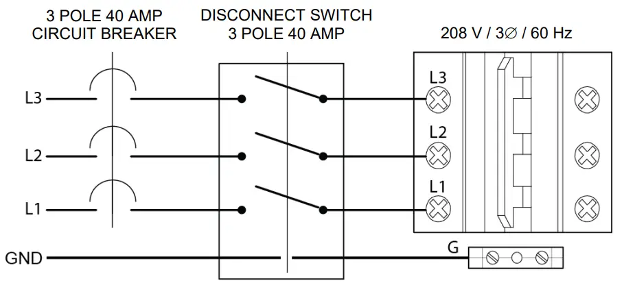
Diagram 7: BMK4000-5000N: 208 V / 3ø / 60 Hz Wiring Schematic- 4 Wire – DOMESTIC
Multiple Unit Wiring
Whenever multiple units are installed within the same mechanical spaces, electrical code requirements call for a single electrical shutoff for emergency use. It is the responsibility of the electrical designer to comply with local codes and regulations affecting an individual installation.
Change Log:
| Date | Description | Changed by |
| 6/9/2020 | Rev 0: Added BMK5000N information where applicable. | Linley Thobourne, Chris Blair |
| 8/6/2020 | Rev P: Added diagram and description of E-Stop power shutoff switch to Section 4. Added 208 V row to BMK 4000/5000N — Domestic, changed amperage from 15 to 20 in Sections 2 and 4. Added new wiring schematic diagrams 6a, 6b and 7 for the BMK4000 & 5000N. | Chris Blair |
![]()
![]() © AERCO International, Inc., 2020
© AERCO International, Inc., 2020


