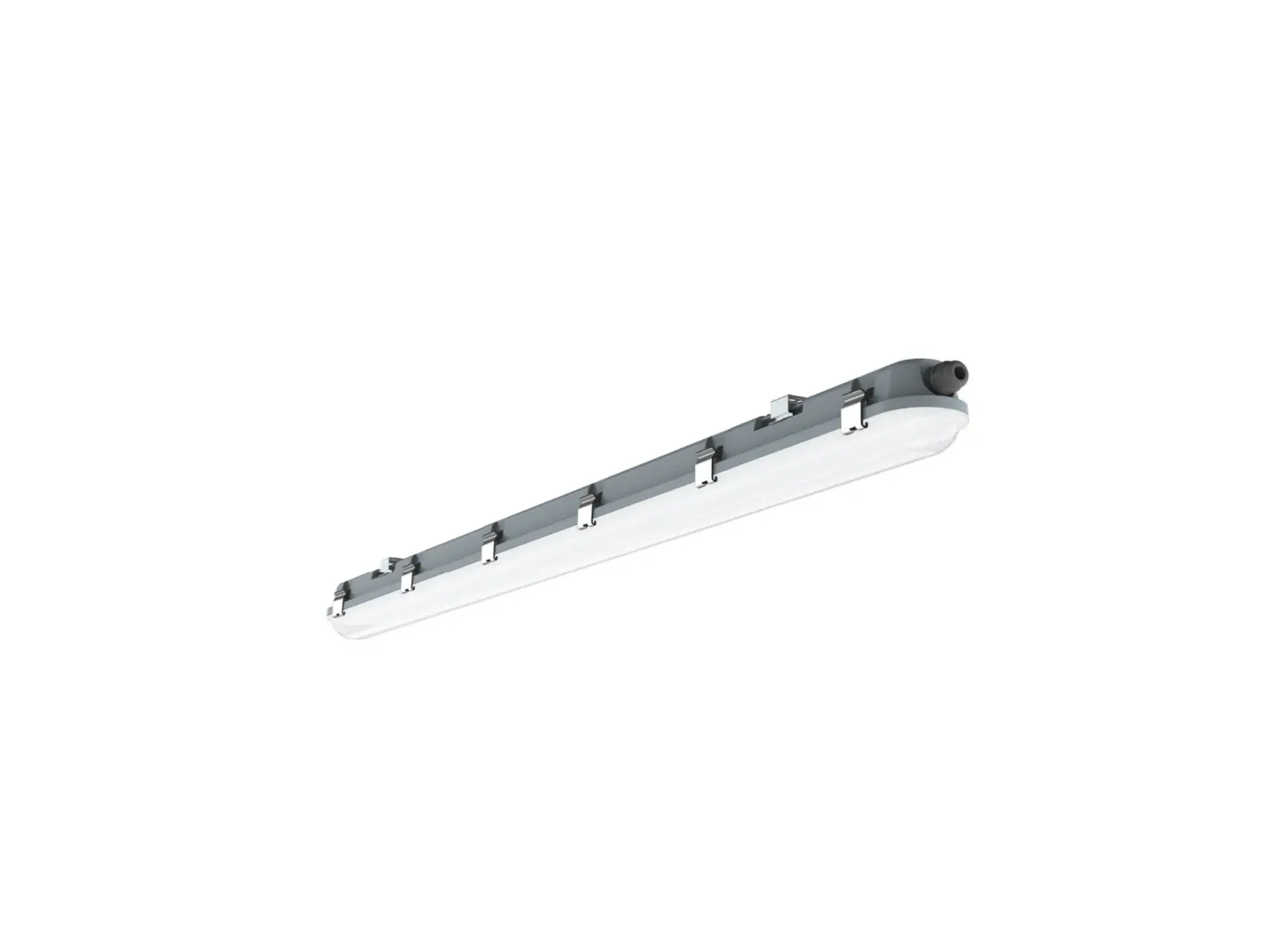
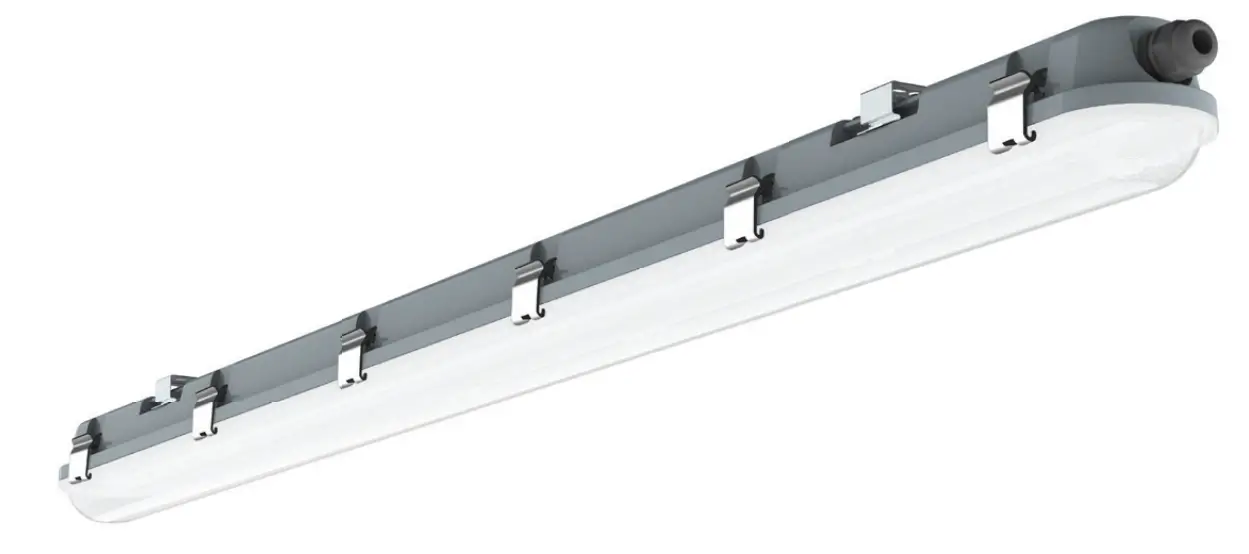
V-TAC VT-150148S LED Waterproof Fitting with Sensor
SINGLE UNIT INSTALLATION INSTRUCTIONS
STEP 1: Switch OFF the power before starting the installation.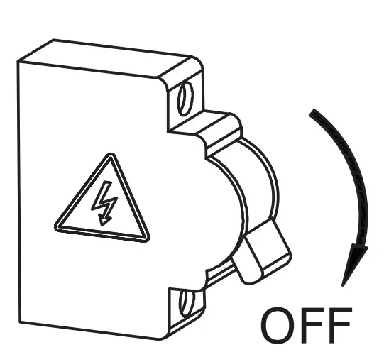
STEP 2: Fix the mounting brackets onto the ceiling using screws and expansion plug(included). Please refer to table for installing the mounting bracket distance points.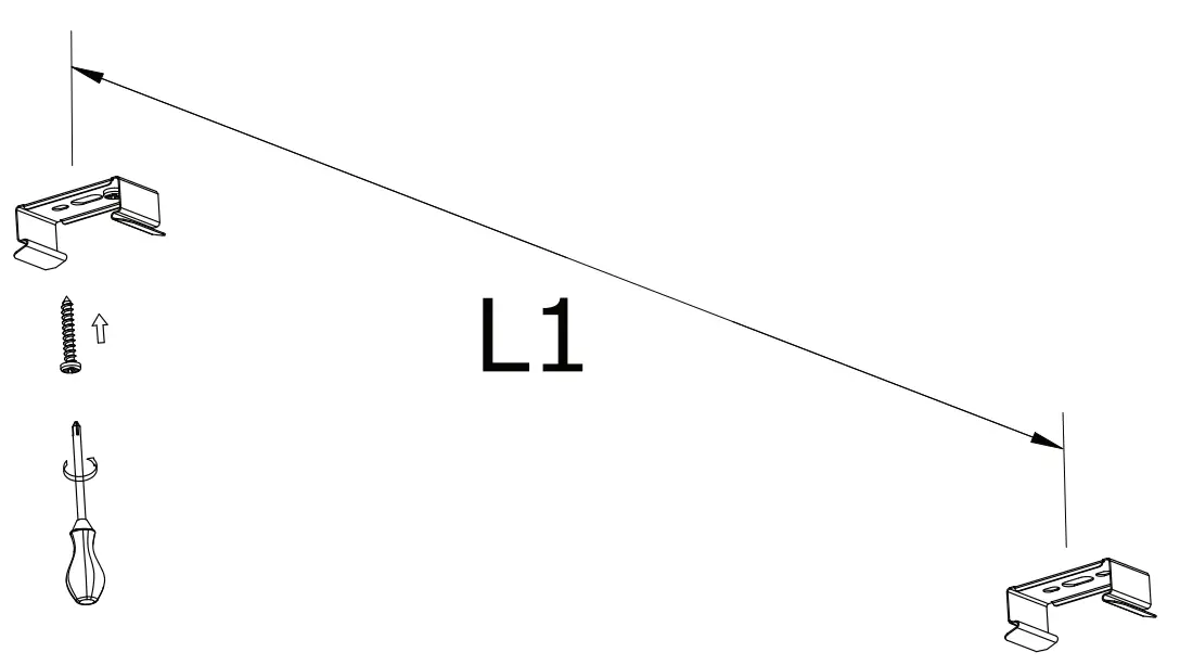
STEP 3: Mount waterproof lamp onto the mounting brackets.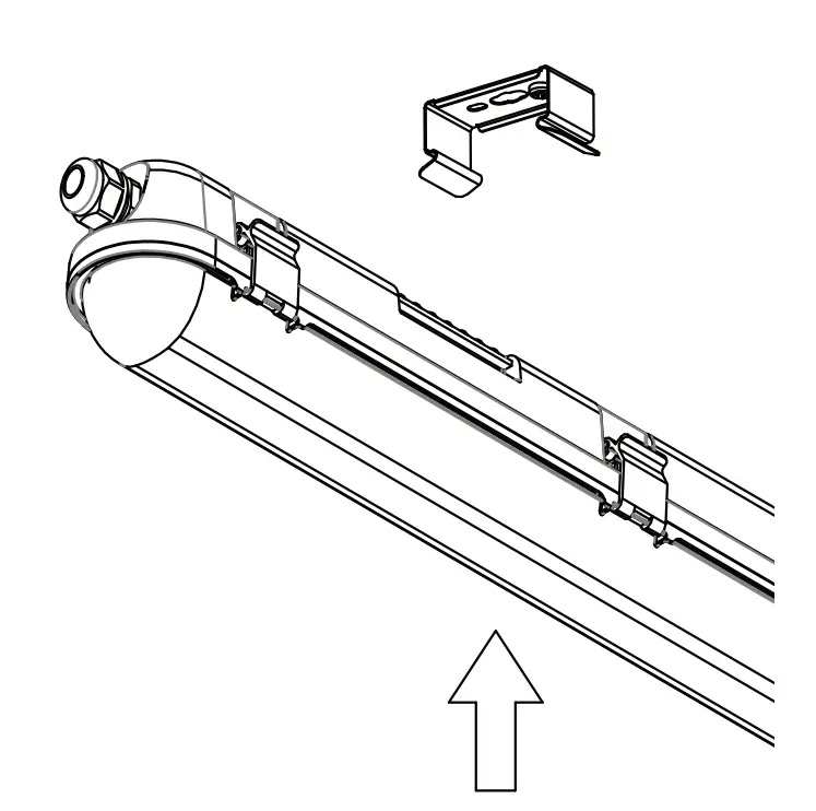
STEP 4: Open the side clips of waterproof fitting and open the diffuser as shown in the diagram.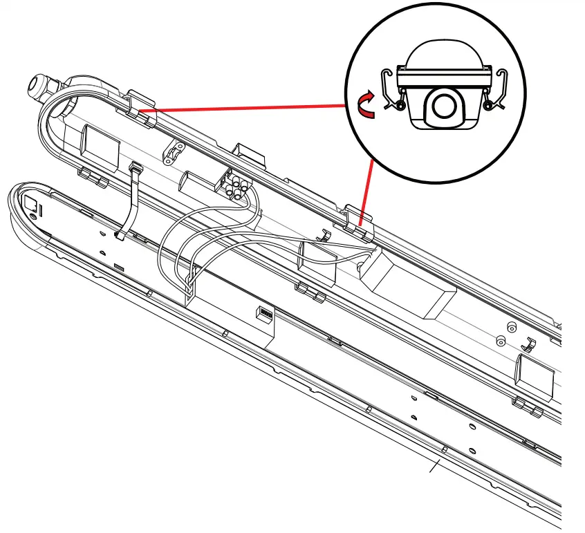
STEP 5: Fasten the waterproof connector clockwise from the first end and insert the cable through the waterproof connector and wire into the terminal block from one end [L(Live) & N(Neutral)] and wire the sensor into other side or terminal block. Wiring must done according to the schematic diagram.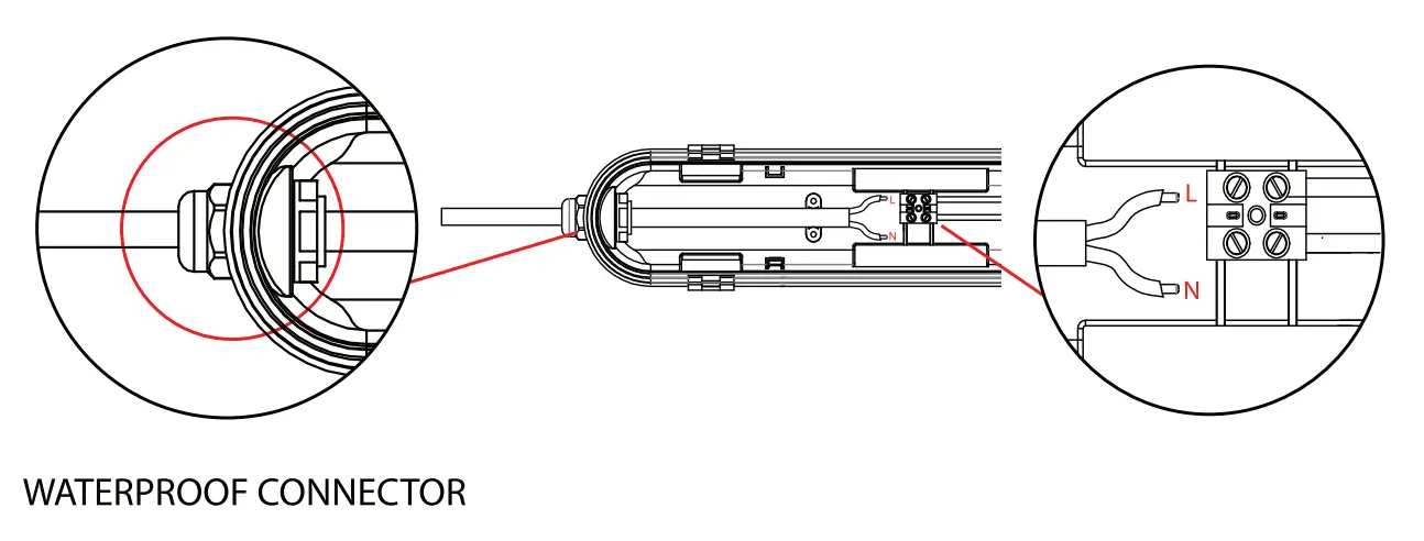
STEP 6: Install the diffuser to the waterproof fitting and close the clips.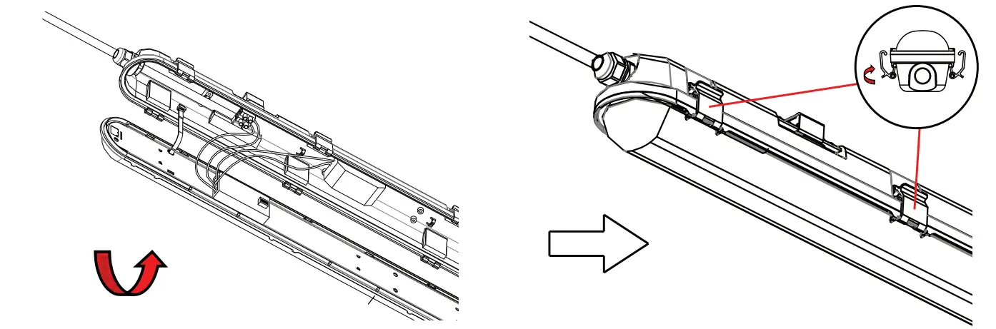
STEP 7: Wire the waterproof fitting to the main power supply. Ensure to use waterproof terminal block [not included].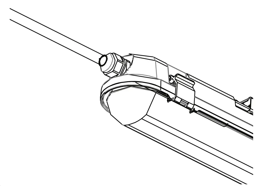
STEP 8: Switch ON the power to test the light.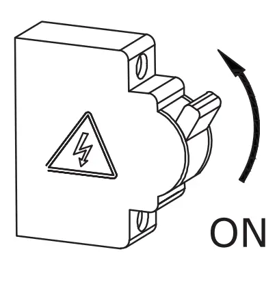
MULTIPLE (LINKABLE) UNITS INSTALLATION INSTRUCTIONS
Note: Please refer to the model number and max linkable units which can be linked together. Based on the max linkable units select the max waterproof fittings which you would like to connect.
STEP 1: Switch OFF the power before starting the installation.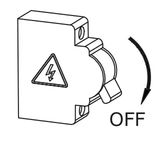
STEP 2: Fix the mounting brackets onto the ceiling using screws and expansion plug(included). Please refer to table for installing the
mounting bracket distance points.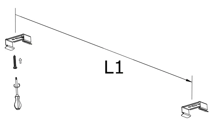
STEP 3: Mount waterproof lamp onto the mounting brackets.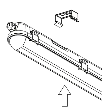
STEP 4: Open the side clips of waterproof fitting and open the diffuser as shown in the diagram.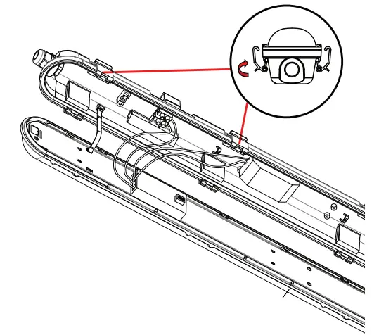
STEP 5: Wiring 1st waterproof fitting from both the ends – Fasten the waterproof connector clockwise from the first end and insert the cable through the waterproof connector and wire into the terminal block from one end [L(Live) & N(Neutral)] and wire the sensor into other side or terminal block. Wiring must done according to the schematic diagram.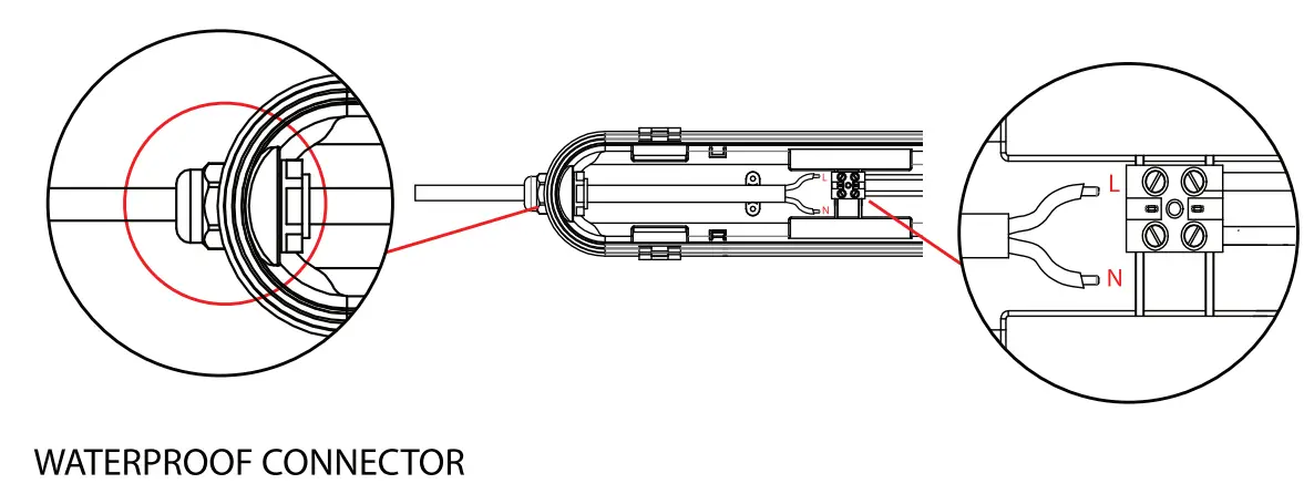
STEP 6: Fasten the waterproof connector from other end of the waterproof fitting and insert the wire into the terminal block. Using the same cable fasten the waterproof connector of the 2nd waterproof fitting and wire into the terminal block.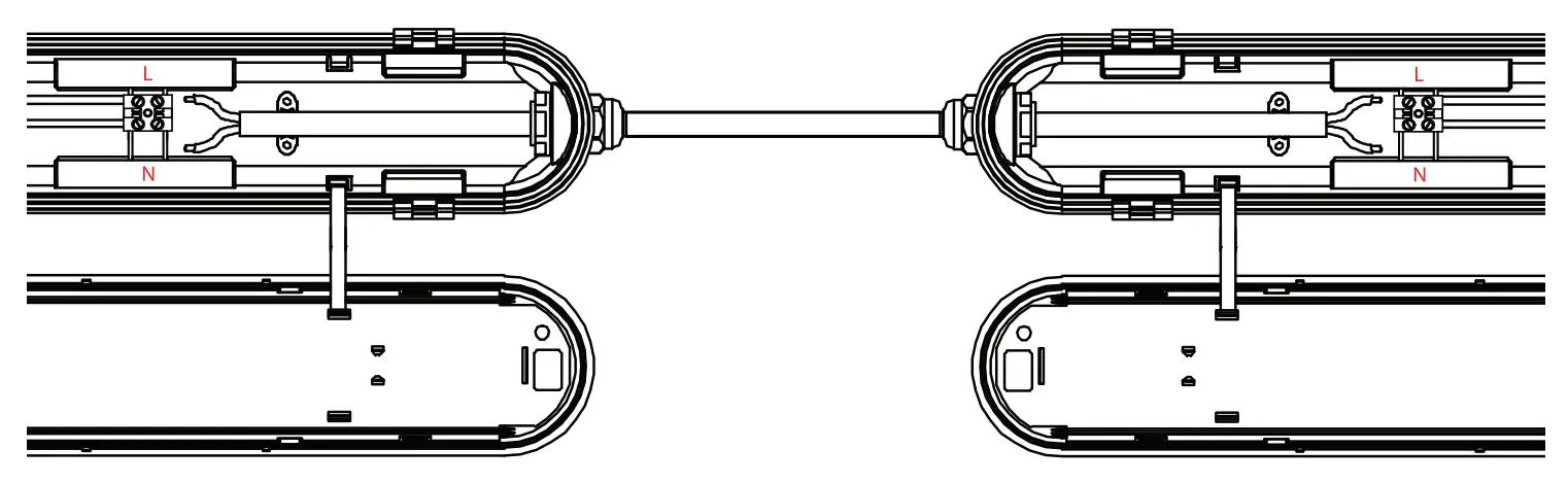
STEP 7: Install the diffuser to the waterproof fitting and close the clips.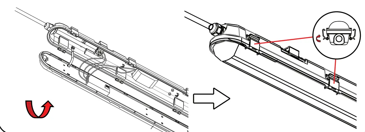
STEP 8: Wire the waterproof fitting to the main power supply. Ensure to use waterproof terminal block [not included].
STEP 9: Switch ON the power to test the light.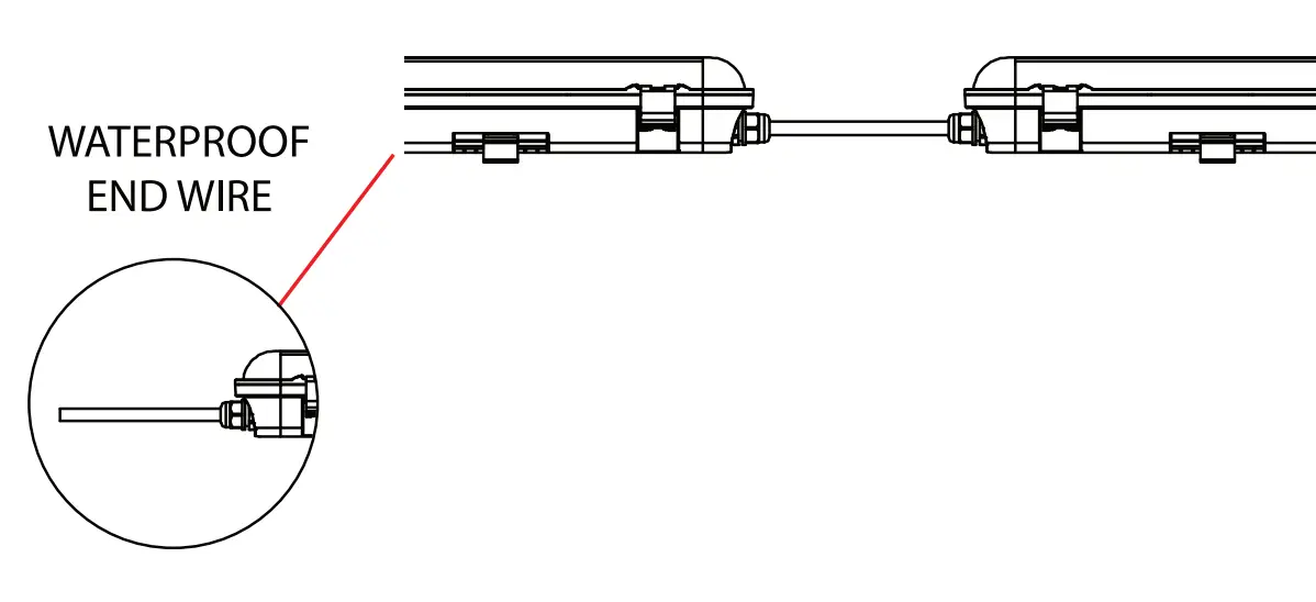
SENSOR CONFIGURATION
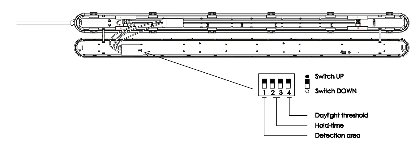
SENSOR SETTINGS
1 | |
| 100% | |
| 50% |
| 2 | 3 | |
5s | ||
1 min | ||
3 min | ||
10 min |
4 | |
Disable | |
301ux |
DETECTION AREA
In this area, movement will be detected and able to trigger the sensor. 100% detection area is also known as the strong sensitvity.
HOLD-TIME
The period of light keeping 100% brightness after moving objects leave the detection area.
DAYLIGHT THRESHOLD
Definition of the ambient brightness; only when the ambient brightness is lower than the preset specific lux amount, the sensor will work; when it’s preset as “disable”,the sensor works everytime it detects motion regardless the ambient brightness.
TECHNICAL DATA
| MODEL | WATTS | LUMENS | CRI | OF | BEAM ANGLE | DIMENSION |
| VT-120136S | 36W | 4320LM | 80 | 0.9 | 120° | 1200x72x78mm |
| VT-150148S | 48W | 5760LM | 80 | 0.9 | 120° | 1500x72x78mm |

SENSOR TECHNICAL DATA:
| SKU 6622 | Switching capacity | Input Voltage | Stand-by power | Detection Area | Operating Temperat ure | Daylight threshold | Microw ave frequency | Hold Time | Motion Detection | Microwave power | Mounting height | Detection range |
| 6622 | M ax, l OOW | AC: 220- 240V, S0/60Hz | o.sw | 50%/ 100% | -2s·c~+60°c | 30Lux/ Disable | 5.8GHz ±7SMHz | Ss/lmin/ 3mi n/ 10min | o.s~1.sm/s | <0.3mW | 2.S-4m / 8.2-13.12ft (Ceiling Mounted) | !2)4 – l 0m/ 13 . 12 – 32.8ft (Ceili ng Mounted) |
INTRODUCTION & WARRANTY
Thank you for selecting and buying V-TAC product. V-TAC will serve you the best. Please read these instructions carefully before starting the installation and keep this manual handy for future reference. If you have any another query, please contact our dealer or local vendor from whom you have purchased the product. They are trained and ready to serve you at the best. The warranty is valid for 3 years from the date of purchase. The warranty does not apply to damage caused by incorrect installation or abnormal wear and tear. The company gives no warranty against damage to any surface due to incorrect removal and installation of the product. The products are suitable for 10-12 Hours Daily operation. Usage of product for 24 Hours a day would void the warranty. This product is warranted for manufacturing defects only.
WARNING!
- Please make sure to turn off the power before starting the installation.
- Installation must be performed by a qualified electrician.
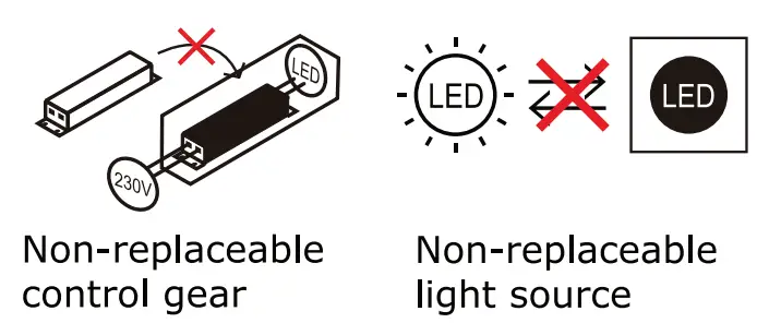
- The light source of this luminaire is not replaceable, when the light source reaches its end of life the whole luminaire should be replaced.
- If the external flexible cable or cord of this luminaire is damaged, it shall be exclusively replaced by the manufacturer or his service agent or a similar qualified person in order to avoid a hazard.
![]() This marking indicates that this product should not be disposed of with other household wastes.
This marking indicates that this product should not be disposed of with other household wastes.
![]() Caution, risk of electric shock.
Caution, risk of electric shock.

MULTI-LANGUAGE MANUAL QR CODE
Please scan the QR code to access the manual in multiple languages.


IN CASE OF ANY QUERY/ISSUE WITH THE PRODUCT, PLEASE REACH OUT TO US AT: [email protected] FOR MORE PRODUCTS RANGE, INQUIRY PLEASE CONTACT OUR DISTRIBUTOR OR NEAREST DEALERS. V-TAC EUROPE LTD. BULGARIA, PLOVDIV 4000, BUL.L.KARAVELOW 9B