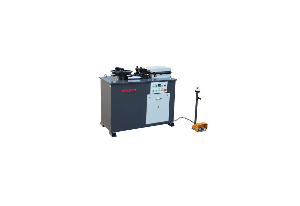
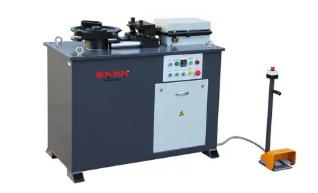
KAKA INDUSTRIAL JTB-50 Tube Bending Machine Instruction Manual

About the Product:
This Tube bending machine is a motor-driven tool set for special purposes, can make adjustments to workpiece holdings either mechanically or hydraulically. By utilizing the metal materials’ adaptable distortion, the tool can bend workpieces such as low-carbon and stainless round tubes, square tubes, steel angles, I-shaped steel stripes and round steel bars to achieve your desired shapes. Being indispensable equipment for construction and beautification works today, can be widely used in the field of building construction, decoration industry, furniture building and garden construction.
The equipment features “one-touch” operation on single workpiece and data-program controlled mass processing. Being easy to operate, reasonable in composition, and low power consumption with high work efficiency, the equipment is ideal for bending metal pipes.
Ⅱ. Specifications:
| Items | Technical Parameters | ||
|
Max. Size of Processing Materials (mm) | Round Pipe | Max. | Φ51 |
| Min. | Φ16 | ||
| Stainless steel pipe | Max. | Φ38 | |
| Min. | Φ16 | ||
| Square pipe | Max. | 50×50 | |
| Min. | 16×16 | ||
| Maximum Bending Angle | 180º | ||
| Rate of Main shaft Rotation r/min | 5 | ||
| Thickness(mm) | 1-5 | ||
| Main Motor Power (kW) | 2.2 | ||
| Hydraulic Motor for specific purpose (kW) | 1.1 | ||
| Packing Sizes(L×W×H)cm | 145×69×117 | ||
| Net Weight | 550 kgs | ||
| Gross Weight | 620 kgs | ||
User’s Guide:
Pre-Use Preparations:
- Read the instructions for the operation of your model carefully before
- Check the accessories delivered along with the machine, remove the guard angle irons of the console panel and fix the panel with such angle
- Add lubricant before trial Make sure that lubricant isinfused to the marked parts of gear box and the required level of lubricant is satisfied.
- For machine with hydraulic power, ordinary hydraulic oil YA-N46 maybe added into it’s hydraulic oil tank and make sure that the amount of the oil reaches the marked level. The first oil infusion may go beyond such marked
- Turn AUTO/MANUAL knob to MANUAL, press Forward spot-turn
button to make sure that main shaft is moving clockwise.
- Press EMG STOP button in times of mounting or dismounting dies to stop the running shaft. Never mount or dismount a die until the main shaft comes to full
- Keep away from the main shaft and dies when machine is
- Make sure that the machine is disconnected from power before cleaning or checking the
- The machine has been well tested for trial before delivery. Please simply secure your machine on a smooth, plain
- Cleaning: Make sure that each part of the machine is in normal condition, removing any obstacles nearby to ensure proper operation of the
- Wirings can be conducted exclusively by professionals to ensure sound
- Always identify and use the right bending dies in accordance with the specifications of the work-pieces that you Never force your machine to do work beyond its capacity.
Ⅳ. Operation:
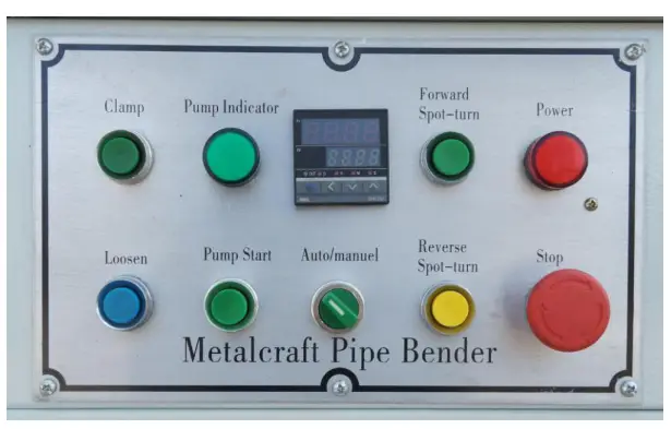
- Clamp: Work at Manual mode, press on this button to clamp the
- Loosen: Work at Manual mode, press on this button to loosen the
- Pump Indicator: when pump start, Light
- Pump Start: Press on this button to start
- Auto/ Manual: Select Auto mode or Manual mode for
- Forward spot-turn: Work at Manual mode, press on this button to forward bending
- Reverse Spot-turn: Work at Manual mode, press on this button to counterclockwise
- Power: When start main power switch, Light
- Stop: Press on this button to cut off power
Preparation before bending
- Choose the proper dies for the material you are to work on, and assemble the dies on the
- Adjust limited switch according to dies size, to make sure that the #2 Rear dies can press the workpiece at the proper
- Trial operation is advised. Connect the machine with power supply (the power indicator now lights up), activate the oil pump power supply to turn on the hydraulic oil
- Select Manual or Auto mode, start
Manual Mode
- Turn the knob to
- Place the workpiece into the die groove and fasten it by #20 Pipe
- Press Clamp button to make the sliding block moves to the set point and make sure workpiece be clamped
- Press Forward spot-turn button to make the reversing valve lever rotary forward so that the hydraulic rod and pressing wheel can squeeze the workpiece to the desired degree of
- Press Reverse Spot-turn button to make the reversing valve lever rotary
- Press Loosen button to make the sliding block moves
- Take off
Note: At manual mode, angle setting function is invalid.
3. Auto Mode
- Turn the knob to
- Place the workpiece into the die groove and fasten it by #20 Pipe
- Set the proper angle want to bend (0-180º).
- Step on the pedal and the machine will perform fastening, arc bending and repositioning automatically. Make sure that the machine works properly by repeating the steps before bending the
- Take off
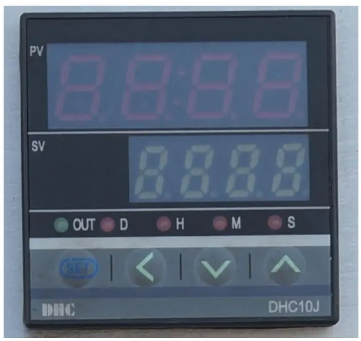
Ⅴ. Set Counter
PV: Actual bending angle SV: Required bending angle
- The required angle can be defined by the counter. E.g. if the bending angle is required to be 90º, then the counter should be set up to 90º.
- Press the Forward spot-turn button (or step on the foot-pedal) until the desired angle where it’ll stop automatically and the task
The way to set counter:
- Press “set” for one second, and then setting value SV is
- now press< to set multiple, when you adjust the multiple you want, then the digit is flickering.
- Press ∨ ∧ adjust the size of the
- Press “set” for one second again, quit adjust Then setting value SV is stopped flicker. Setting is finished.
Note: 1. if you press “set” for three seconds carelessly into adjusting counter mode; please don’t change the number anyway. Press “set” continuously until SV shows 0000 correctly. Otherwise the counter can’t work normally. Then use the last four steps to set counter.
- “set” also has the function to back zero.
Lubrication and Maintenance:
- Bearings of all axis must be lubricated with calcium grease on 6-month basis.
- Users are advised to check the condition of the electrical devices on regular basis to ensure the soundness of such devices and ground Turn off the machine in the event of occurrence of any trouble or abnormal sound. Disconnect the machine from the power source, find out the trouble and eliminate it timely.
- Clean the machine after work and apply anti-rust oil onto the unpainted parts of the machine, keep it in good
- A good mastery of the operating sequence will avoid wrong
- Pay close attention to any damage caused to the adjustment
Replace it if necessary to avoid personal injuries.
Ⅶ. Troubleshooting:
| Description of Troubles | Possible Cause | Countermeasures |
| Sliding block refuse to move | 1. Wrong direction of oil pump motor movement. | 1. Change phase sequence direction |
| 2. Insufficient amount of oil in oil tank. | 2. Add oil to the required level | |
| Excessive volume of noise | 1. Blockage of oil inlet pipe 2. Air in oil seal of oil pump | 1. Check the pipe
2. Replace oil seal |
| Poor volume of pressure | Deposition of guiding pressure valve | Re-adjust |
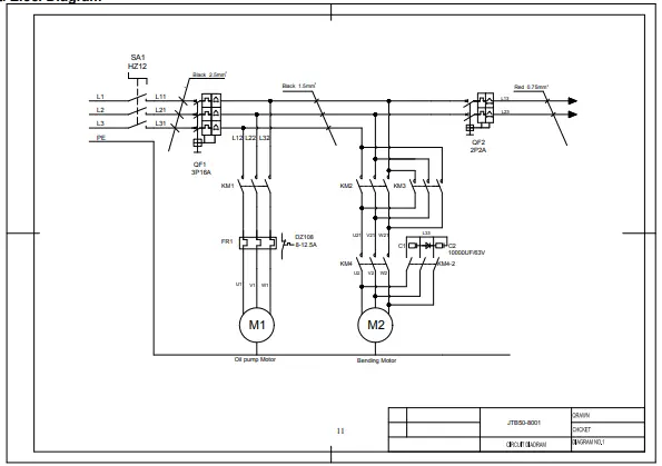
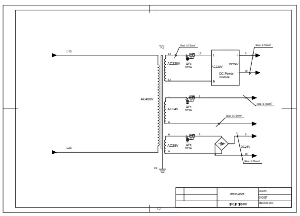
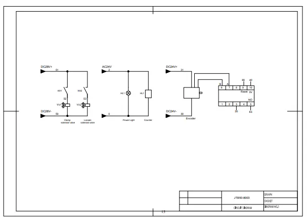
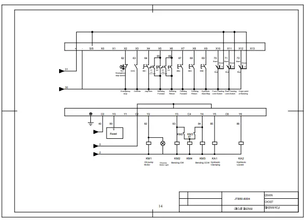
Elec. Diagram
Parts drawing and Parts list
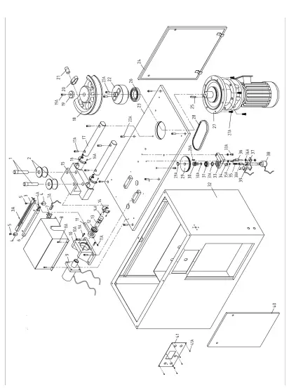
| Part # | Desc | Q’ty | Part # | Desc | Q’ty | |
| 1 | Axis Pin | 2 | 23 | Worktable | 1 | |
| 2 | Rear Dies | 2 | 23A | Screw M10x25 | 6 | |
| 3 | Limited guide bar | 1 | 24 | Rear Door | 1 | |
| 3A | Screw M3x8 | 6 | 25 | Flat Key 16 | 1 | |
| 4 | Limited Block | 2 | 26 | Bearing 6020 | 1 | |
| 4A | Screw M6x15 | 1 | 27 | Motor | 1 | |
| 5 | Stop Screw | 2 | 27A | Bolt M12x40 | 8 | |
| 6 | Slide Rail | 1 | 28 | Belt | 1 | |
| 7 | Limited switch Seat | 1 | 28A | Flat Key 6 | 1 | |
| 7A | Limited Switch | 1 | 29 | Belt Wheel | 1 | |
| 8 | Upper Cover | 1 | 29A | Check Ring | 1 | |
| 8A | Screw M8x10 | 4 | 30 | Shaft | 1 | |
| 9 | Hydraulic Cylinder | 1 | 30A | Check Ring 20 | 1 | |
| 9A | Screw M12x35 | 4 | 31 | Bearing 6204 | 1 | |
| 10 | Fixed Seat for Hydraulic cylinder | 1 | 31A | Check Ring | 1 | |
| 10A | Screw M16x60 | 4 | 32 | Pedestal | 1 | |
| 11 | Connecting Rod | 1 | 33 | Fixed Seat for Encoder | 1 | |
| 11A | Set Screw M6x8 | 2 | 33A | Screw M8x40 | 2 | |
| 12 | Locknut | 1 | 34 | Pointer | 1 | |
| 13 | Ejector Rob | 1 | 35 | Fixed Screw | 1 | |
| 14 | Pad | 1 | 35A | Nut M6 | 1 | |
| 14A | Bolt M6x16 | 3 | 36 | Connection Screw | 1 | |
| 15 | Slide Rest | 1 | 36A | Nut M10 | 2 | |
| 16 | Dust Cover | 2 | 37 | Junction plate | 1 | |
| 16A | Sunk Screw M4x10 | 6 | 38 | Encoder | 1 | |
| 17 | Slideway | 2 | 38A | Coupler | 1 | |
| 17A | Screw M12x40 | 6 | 39 | Limited Switch | 1 | |
| 18 | Bending Die | 1 | 40 | Front Door | 1 | |
| 19 | Press Cover | 1 | 41 | Panel | 1 | |
| 19A | Screw M10x30 | 1 | 41A | Screw M6x8 | 6 | |
| 20 | Pipe Clamp | 1 | ||||
| 21 | Axis Pin | 1 | ||||
| 22 | Rotary seat | 1 | ||||
| 22A | Screw M8x20 | 2 |
Note: This manual is only for your reference. We reserve the right to improve the machine without notice. Please note the local voltage for operating this electric machine.


