Syvecs V1.3 50Hz GPS Module User Guide
INSTRUCTION
This document is intended for use by a technical audience and describes a number of procedures that are potentially hazardous. Installations should be carried out by competent persons only.
Syvecs and the author accept no liability for any damage caused by the incorrect installation or configuration of the equipment.
Please Note that due to frequent firmware changes certain windows might not be the same as the manual illustrates. If so please contact the Syvecs Tech Team for Assistance.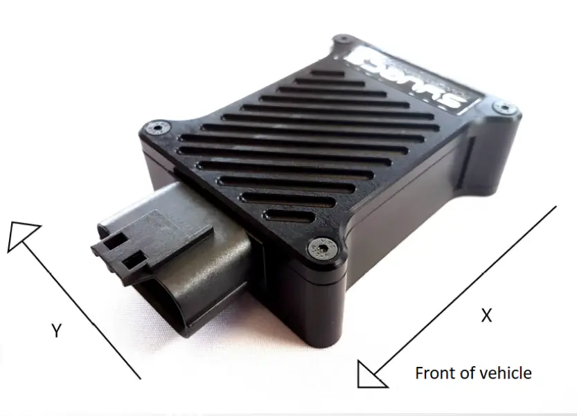
The Syvecs 50hz GPS Module is designed to provide even more control to our engine control units with accurate global positioning, acceleration forces for 6 axis and GPS Speed. Fast positioning lock with hot restarts due to internal battery storing last positioning data.
The following parameters are available from our 50Hz GPS Module.
| GPS Lateral Position | GPS Mode Letter |
| GPS Longitude Position | GPS Fix Quality |
| GPS Speed | Lateral G Force |
| GPS Course | Longitudinal G Force |
| GPS Altitude | Vertical G Force |
| GPS Time and Date | Roll |
| Number of Locked Satellites | Pitch |
| Yaw |
Packaged in a lightweight CNC billet aluminium case with a waterproof 18way JAE Connector. Mating Socket – JAE – MX23A18SF1
Wiring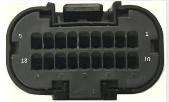
| Pin Number | Pin Function |
| 3 or 4 | Ground |
| 5 | CAN1 LOW – 500Kb |
| 6 | CAN0 LOW – 1mb |
| 12 | 12V Supply |
| 14 | CAN1 Hi – 500kb |
| 15 | CAN0 HI – 1mb |
S6Plus with PNP Kits connect GPS Can1 to S6Plus Can1 (C8/C9) – Generic S6+ ECU Speak to [email protected] S7Plus connect GPS Can0 to S7Plus Can2 (B2/B3) – if X10 Expander is wired to Can2 then Wire to Can1 on S7 like S6Plus above
S8 & S12 connect GPS Can0 to Either ECU Can1 or Can2
No Termination Resistor is set on the GPS Module so the GPS needs to be wired as a Node on the Canbus
CAN Output Description
All in Big Endian Format apart from 0x679h &0x690h
Can0 – 1MB Speed
ID 679h & 690h – GPS Position ( LSB) – Motec M1 (Base ID 0x690h
| Byte 1 | Byte 2 | Byte 3 | Byte 4 | Byte 5 | Byte 6 | Byte 7 | Byte 8 |
| GPS latitude in ten-thousands of a minute of arc as a signed 32-bit value. Positive values are north of the equator. negatives are south. | GPS longitude in ten-thousands of a minute of arc as a signed 32-bit value. Positive values are east of the Greenwich Meridian, negatives are west | ||||||
ID 680h – GPS Position
| Byte 1 | Byte 2 | Byte 3 | Byte 4 | Byte 5 | Byte 6 | Byte 7 | Byte 8 |
| GPS latitude in ten-thousands of a minute of arc as a signed 32-bit value. Positive values are north of the equator. negatives are south. | GPS longitude in ten-thousands of a minute of arc as a signed 32-bit value. Positive values are east of the Greenwich Meridian. negatives are .• rest | ||||||
ID 681h – GPS Course, Speed and Altitude
| Byte 1 | Byte 2 | Byte 3 | Byte 4 | Byte 5 | Byte 6 |
| Course in hundredths of a degree as an unsigned 16-bit value A value of 0 indicates due North | Speed in centimetres per second as an unsigned 16-bit value. | Altitude in metres as a signed 16-bit value. Negative values indicate a position below mean sea level | |||
ID 682h – GPS Time and Date
| Byte 1 | Byte 2 | Byte 3 | Byte 4 | Byte 5 | Byte 6 | Byte 7 | Byte 8 |
| Day of month as an unsigned-8-bit value | Month of year as an unsigned 8-bit value | Year of century as an unsigned 8-bit value | Hour of day as ar unsigned 8-bit value. | Minute of hour as anunsigned 8 –bite value | Second of minute as an unsigned 8-bit value | Thousandths of a second as unsigned 16-bit value | |
ID 683h – Accelerometer
| Byte 1 | Byte 2 | Byte 3 | Byte 4 | Byte 5 | Byte 6 | Byte 7 | Byte 8 |
| Latitudinal acceleration in thousandths of a G as a signed 16-bit value. Positive values represent acceleration to the left (as when turning to the right). negative to the right as turning to the left). | Longitudinal acceleration in thousandths of a G as a signed 16-bit value. Positive values represent increasing fon…ard speed. negatives decreasing. | Vertical acceleration in thousandths of a G as a signed 16-bit value. Positive values represent upwards acceleration, negative downwards. | Accelerometer temperature in tenths of a degree C as a signed 16-bit value | ||||
ID 684h – Gyroscope
| Byte 1 | Byte 2 | Byte 3 | Byte 4 | Byte 5 | Byte 6 | Byte 7 | Byte 8 |
| Roll in terths of a degree per second as a sgned 16-b t integer Pcsitive \,alues indicate roll towarc the right. negative to tl-e left. | Pilch :n tenths of a degree per seconc as a signec 5-bit integer. Positive values indicate Lryivard pitch. regative dovi•vard. | Yaw in tenths of a degree per second as a s gned 16-bit integer. Pcsitive values indicate yaw to the right, negative to tt-e left. | Gyroscope temperature in tenths of a degree C as a signed 16-bit value | ||||
ID 685h – GPS Status
| Byte 1 | Byte 2 | Byte 3 | Byte 4 | Byte 5 | Byte 6 |
| Horizontal dilution of precision in tenths of a metre. | Fix quality indicator (0=fix unavailable. 1=valid fix in SPS mode. 2=valid fix in differential GPS mode) | Number of Satellites in view | GPS mode letter (N=data not valid A=autonomous mode. D=differential mode. E=estimated mode) | GPS status letter (A=data valid, V=receiver warning) | |
Can1 – 500kb Speed
ID F0h – GPS Position
| Byte 1 | Byte 2 | Byte 3 | Byte 4 | Byte 5 | Byte 6 | Byte 7 | Byte 8 |
| GPS latitude in ten-thousands of a minute of arc as a signed 32-bit value. Positive values are north of the equator. negatives are south. | GPS longitude in ten-thousands of a minute of arc as a signed 32-bit value. Positive values are east of the Greenwich Meridian. negatives are west | ||||||
ID F1h – GPS Course, Speed and Altitude
| Byte 1 | Byte 2 | Byte 3 | Byte 4 | Byte 5 | Byte 6 |
| Course in hundredths of a degree as an unsigned 16-bit value A value of 0 indicates due North | Speed in centimetres per second as an unsigned 16-bit value. | Altitude in metres as a signed 16-bit value_ Negative values indicate a position below mean sea level | |||
ID F2h – Accelerometer
| Byte 1 | Byte 2 | Byte 3 | Byte 4 | Byte 5 | Byte 6 | Byte 7 | Byte 8 |
| Latitudinal acceleration in thousandths of a G as a signed 16-bit value. Positive values represent acceleration to the left (as when turning to the right). negative to the right as when turning to the left). | Longitudinal acceleration in thousandths of a G as a signed 16-bit value. Positive values represent increasing fori/ard speed. negatives decreasing. | Vertical acceleration in thousandths of a G as a signed 16-bit value. Positive values represent upwards acceleration. negative downwards. | Accelerometer temperature in tenths of a degree C as a signed 16-bit value. | ||||
ID F3h – Gyroscope
| Byte 1 | Byte 2 | Byte 3 | Byte 4 | Byte 5 | Byte 6 | Byte 7 | Byte 8 |
| Rcll in terths of a degree per second as a sgned 16-b t integer Pcsitive values indicate roll to,frrarc the right. regative to the left. | Pilch in tenths of a degree per second as a signec 16-bit integer. Positive values indicate upward pitch. regative dovm-iard. | Yaw in tenths of a degree per se:ond as a s gned 16-bit integer. Pcsitive values indica:e ya,-/ to the right. negative to the left. | Gyroscope temperature in tenths of a degree C as a signed 16-bit value | ||||
ID F4h – GPS Status
| Byte 1 | Byte 2 | Byte 3 | Byte 4 | Byte 5 | Byte 6 |
| Horizontal dilution of precision in tenths of a metre. | Fix quality indicator (0=fix unavailable. 1=valid fix in SPS mode. 2=valid fix in differential GPS mode) | Number Of stellites in view | GPS mode letter (N=data not valid A=autonomous mode. D=differential mode. E=estimated mode) | GPS status letter (A=data valid. \/=receiver warning) | |
Syvecs Calibration Setup
S7, S8 & S12
The Syvecs 50hz GPS module can be connected to Can1 or Can2 on the S8/S12.With the S7Plus its best to use Can2. To enable in Scal users need to select the GPS- AG50 as shown below in Datastream as well as the Recieve Canbus its wired to. A device – program is needed after this selection to activate.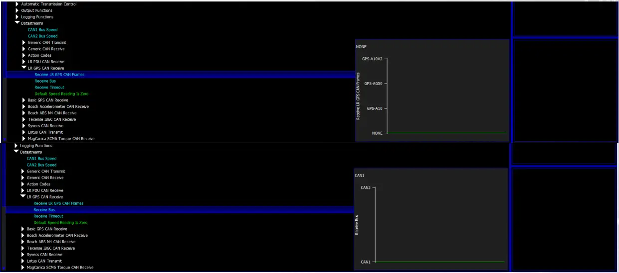
After enabling the monitoring items below will become available
| gpsLat | gpsStatus |
| gpsLong | gpsSatInfo |
| gpsSpeed | longG |
| gpsCourse | latg |
| gpsAltitude | roll |
| gpsHrzDil | pitch |
| gpsFixQual | vertG |
| gpsNumSats | yaw |
| gpsMode |
S6-I/ S6Plus/ S7-I
The Syvecs GPS 50hz Data is picked up automatically on the S6Plus & S6/S7-I with Firmware 1.82+ after wiring onto the Can1 (C8 & C9) which is the 500kb Canbus with a Plug in Kit. To pickup the Accelerometer info from the Gps module users will need to enable the Accel Rx and Gyro Rx under I/O Configuration and make sure none of the Acceleration sensors are defined in the Pin Assignments.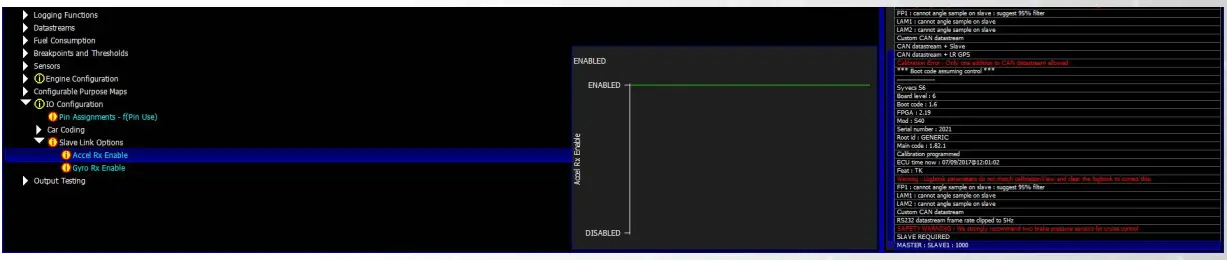
After enabling the monitoring items below will become available
| gpsLat | longG |
| gpsLong | latg |
| gpsSpeed | roll |
| gpsCourse | pitch |
| gpsAltitude | vertG |
| yaw |
The GPS Module needs to be mounted as shown below for the 6 axis of the accelerometer to report correctly.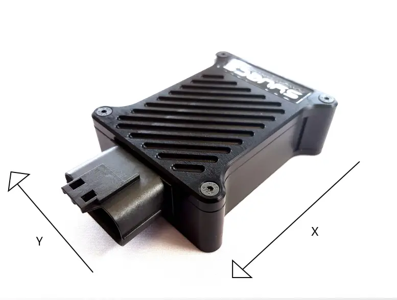
In applications where heavy vibrations are present due to solid engine mounts etc, it is advised to mount the GPS using some rubber washers to absorb some of the vibrations.
After mounting correctly you need to reset the sensor corrections in Scal for the accelerometers. This is done by clicking Device – Sensor Corrections.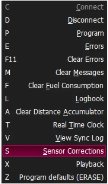
Then highlight the LatG/Long/VertG/Yaw/Pitch/Roll and select Reset, followed by Set.
The Long G / Lat G should all read 0 now when the car is level.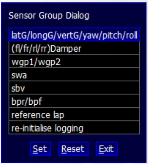
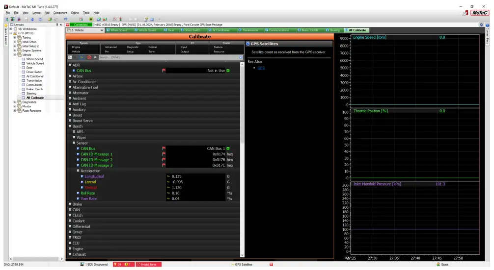
Motec Calibration Setup
M1 Series
The Syvecs 50hz GPS CAN0 can be connected to Can1, Can2 or Can3 on the M1 Series of Ecu’s.
M1Tune users need to head to the All Calibrate Section, select GPS
Set the Can Interface Used and Base ID at 0x690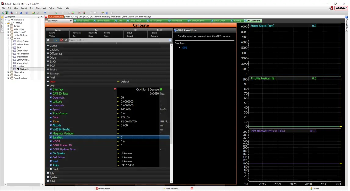
The Gyro/IMU Information needs to come via the Bosch MM5 protocol. Select Bosch in All Calibrate and set the CAD ID Messages as below.