![]() 1420 Emerson Wireless Gateway and E2
1420 Emerson Wireless Gateway and E2
User Guide
1420 Emerson Wireless Gateway and E2
For a copy of the full Wireless User Manual (P/N 026-1734), click here to download it or contact Emerson Customer Service at 770-425-2724.
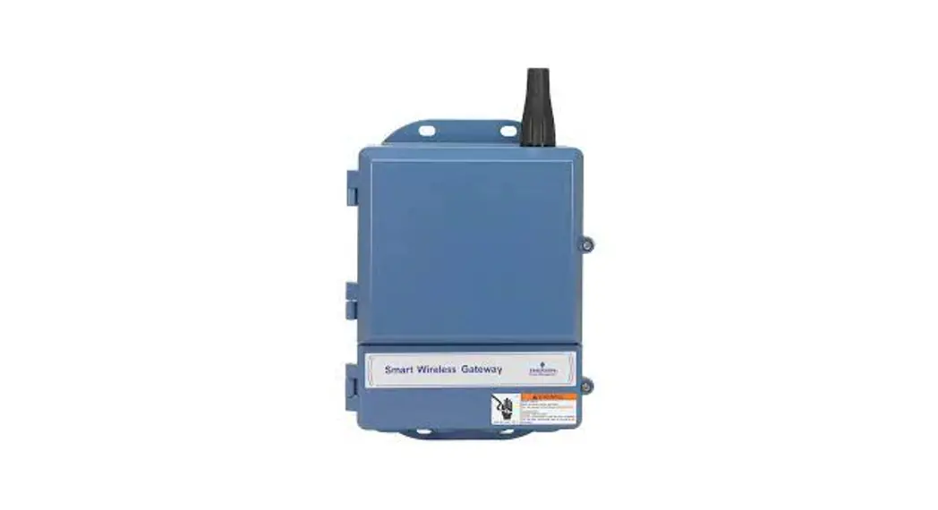
Emerson’s Wireless Module System allows for quick and easy monitoring of a variety of Refrigeration and HVAC applications by connecting temperature probes, product simulators, humidity probes, or switches to the Wireless Module that transmits these signals to the Wireless Gateway. The Gateway translates the signal into usable information to send to the building controller, E2 (version 4.08 or higher), or Site Supervisor, where the data can be logged into reports or used by algorithms to make control decisions. The Wireless Gateway can receive signals from up to 99 Modules. The Wireless Module is flexible and configurable with up to three (3) analog or digital inputs that can be used for a variety of applications in Refrigeration and HVAC, eliminating installation materials and costly labor-intensive wiring.
Installing the Wireless Gateway
Installing the Emerson Wireless Gateway for E2 involves mounting and powering the device, and connecting it to E2’s RS485 network.
The Emerson Wireless Gateway requires 24VAC power from a Class 2 Transformer.
Table 1 – Wireless Gateway Power Requirements
| Input Voltage | 24VAC, Class 2, 50/60Hz |
| Power | 10VA |
Because the Gateway is usually mounted away from the transformer, an 18 AWG wire should be used. The AC voltage at the Gateway needs to be at least 19 Volts.
Installing Network Cable
Each E2 will receive a value from an Emerson Wireless
The module must have an Emerson Wireless Gateway installed on its RS485 Network. For E2 controllers, the Gateway will be installed on an RS485 network running MODBUS protocol.
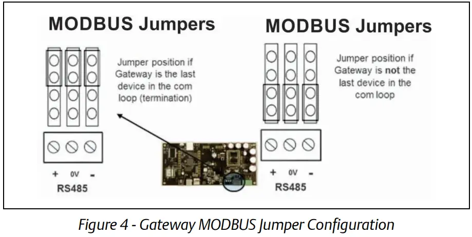
Using a shielded three-conductor network cable (Belden #8641 or equivalent), connect the RS485 Network wire from E2 to the three-terminal connector on the Wireless Gateway board as shown below. For further information about how RS485 networks are configured, refer to the E2 User Manual (P/N 026-1614).
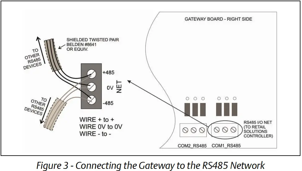
Termination should only be done at the two endpoints of the network. Set termination as appropriate as shown in Figure 4.
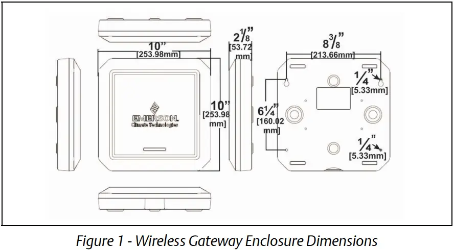
Mounting and Installation Tips
- Gateway Signal Range: 100-ft. radius.
- Mount the Gateway on the ceiling, parallel to the floor.
- Up to 99 Wireless Modules per Gateway.
- Position the Module with the Emerson logo pointing toward the Gateway for maximum performance.
- Try to avoid metal obstructions in the line of sight.
- Mount the Module in a location where 200 lux of light is visible to the solar cell for five (5) or more hours per day.
- If possible, commission a Module from its mounting location to verify good positioning.
- Check the signal strength on the E2 prior to permanently mounting the Modules.
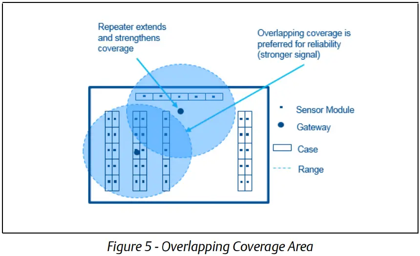
- Low-cost Repeaters are available for applications not requiring additional Gateways.

Set Up and Commissioning in E2
For complete instructions on setup and commissioning, refer to the Wireless User Manual (P/N 026-1734).
Note: E2 Firmware version 3.08/4.08 is required.
- Set the desired COM port for MODBUS.
(Menu, 7, 4, 1, C:3 Serial tab)
• Baud: 19.2 Kbaud
• Data Size: 8
• Parity: Even
• Stop Bits: 1 - Add a Wireless Gateway in the Network Setup screen (Menu, 7, 7, 2, C:3 ECT tab) by changing the quantity of Wireless GW to 1.
- After adding the Gateway, go to the Network Summary screen and select Wireless Gateway and then Commission (Menu, 7, 7, 1, F4: Commission).
- Set the MODBUS address to 247 to match the default address in the Gateway (this address is fixed in the Gateway). Enter 247 or scroll down to 247 and press Enter.
- Press Enter to complete Commissioning.
Table 2- Ordering Information
| Part Number | RF Description |
| 814-3550 | Wireless Gateway/Repeater 902MHz |
| 814-3560 | Wireless Repeater 902MHz, 24VAC |
| 814-3600 | Wireless Module 902MHz with User Selected Inputs; Clean Mode |
| 814-3653 | Wireless Module 902MHz, 3 Temp; Clean Mode with Molex Connector |
| 140-6802 | Wall Mount 24VAC, 20VA Class 2 Transformer |
For a full copy of the Emerson Wireless Module System Installation and Operation Manual, scan the QR Code.

This document may be photocopied for personal use.
Visit our website at www.climate.emerson.com for the latest technical documentation and updates.
Join Emerson Technical Support on Facebook. http://on.fb.me/WUQRnt
For Technical Support call 833-409-7505 or email ColdChain.[email protected]
The contents of this publication are presented for informational purposes only and they are not to be construed as warranties or guarantees, express or implied, regarding the products or services described herein or their use or applicability. Emerson reserves the right to modify the designs or specifications of such products at any time without notice. Responsibility for the proper selection, use, and maintenance of any product remains solely with the purchaser and end-user. ©2022 Emerson is a trademark of Emerson Electric Co.
![]() Document Part # 026-4247 Rev 8
Document Part # 026-4247 Rev 8
©2022 Emerson Digital Cold Chain, Inc.
This document may be photocopied for personal use.
Visit our website at www.climate.emerson.com for the latest technical documentation and updates


