

Signal-Tech LSi Series Outdoor LED Backlit Monument Sign

Instructions
Voltage
This sign operates within an input range of 120VAC to 277VAC.
What You Need:
Phillips Head Screw Driver Control Switch (ordered separately)
Warning: Always turn off the power prior to installation. Be sure any metal debris cleared out of the cabinet.
Power & Communications
- With the sign mounted, open sign cabinet by removing the 2 (two) screws located on the bottom of the front panel.
- With the front hinged panel supported open locate the variable message displays. Each display will have its own wiring.
- Reattach the cabinet to the brackets with the hardware provided.

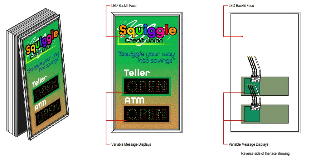
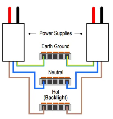
Backlit Panel Wiring Connections
- Turn off incoming power prior to starting installation.
- All terminations should be made using the provided 5-conductor lever-nuts.(No additional wire nuts required.)
- A single Hot input is provided for the backlighting
- Brown Wires: Hot/ACL
- Blue Wires: Neutral/ACN (may be combined with white wire from variable message inserts)
- Green/Yellow Wires: Earth Ground (sign cabinet and power supply grounds combined)

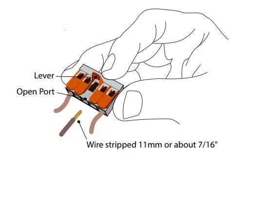
Lever-nut Instructions
- Strip the ends of your input wire to 11mm, using the guide on the side of one of the lever nuts.
- To make a connection, use the wiring scheme pictured to find the correct lever nut.
- Pull up on lever of an open port
- Insert conductor
- Push lever back down

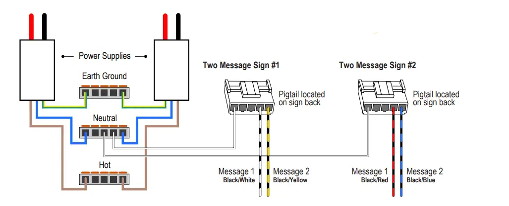
Variable Message Insert Wiring Connections
- Each variable message insert will have a stripped-end wire for each message. Be sure to reference the Wiring Label on the back of each display panel.
(See General Wiring Guidelines below)
- A common neutral is pre-wired; terminate neutral using the lever-nut referenced in the Backlit panel Wiring Instructions.
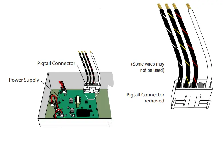
- To make your electrical connections easier, gently unplug the supplied wired pigtail connector from the power supply.
- With your incoming power already running through the mounted back you can easily make all connections to the pigtail using wire connectors.
(See table below for General Wiring Guidelines) - Plug the pigtail connector back into the power supply to finish off the electrical part of your installation. The connector is “keyed” and can only be installed in one orientation
- You’re done with the electrical! Time to close up the sign by pushing the cabinet closed and replacing the two screws you removed from the bottom of the cabinet.
Note: Make appropriate wiring connections per local code.
Sample Wiring Label
Wiring Label Sample for a typical 2 Message OPEN | CLOSED Sign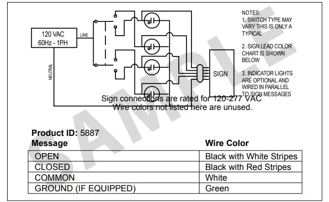
General Wiring Guidelines*
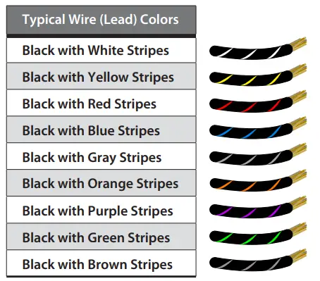
Neutral is solid White and Ground (if equipped) is solid Green.
Note: Refer to the wiring label inside the sign for the specific instructions on wiring your sign. Some wires may not be used.
Warning Statements
Note: Make appropriate wiring connections per local code.
Note: Any holes drilled into sign cabinet MUST be sealed. Failure to do so may cause a short and void warranty.
Note: This unit contains a built-in CLASS 2 LED driver.
Note: This sign is intended to be installed in accordance with the requirements of Article 600 of the National Electric Code and/or other applicable local codes. This includes proper grounding and bonding of the sign.
WARNING: Risk of Fire or Electric Shock. Do Not interconnect output terminations.


