![]() SP 0081 U Smart Panel
SP 0081 U Smart Panel
Instruction Manual KNX Smart Panel 8
Ref.-no.: SP 0081 U
ALBRECHT JUNG GMBH & CO. KG
Volmestraße 1
58579 Schalksmühle
GERMANY
Tel. +49 2355 806-0
Fax +49 2355 806-204
[email protected]
www.jung.de
http://qr.jung.de/ean/4011377195448.htm
Safety instructions and device components
1.1 Safety instructions![]() Electrical devices may only be mounted and connected by electrically skilled persons.
Electrical devices may only be mounted and connected by electrically skilled persons.
Serious injuries, fire or property damage possible. Please read and follow manual fully.
Danger of electric shock. During installation and cable routing, comply with the regulations and standards which apply for SELV circuits.
These instructions are an integral part of the product and must remain with the end customer.
1.2 Device components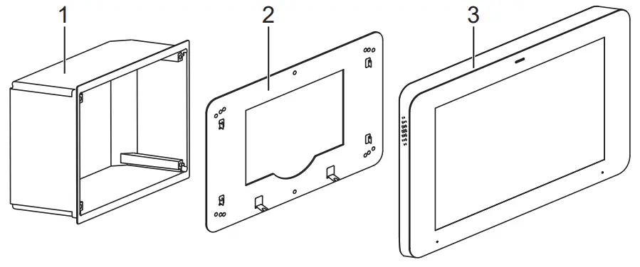 Fig. 1: Device components
- Installation box
- Adapter
- Smart Panel
Function
2.1 System information
This device is a product of the KNX system and conforms to the KNX Directives. Detailed knowledge attained through KNX training is a prerequisite for understanding.
The device is planned, installed and commissioned by means of an external of external project planning software. The latest software version and the technical descriptions can be found on our website at all times.
2.2 Intended use
– Visualising and operating system statuses and information on building automation
– Mounting horizontally (recommended) or vertically
– Mounting in a flush-mounted installation box (ref.-no. EBG 24) or on appliance box according to EN 60670-1 (recommendation: at a depth of approx. 60 mm)
2.3 Product characteristics
– High-resolution HD display
– Proximity sensor
– Capacitive touch screen
– Cleaning mode with touch screen lock
– Fanless, without mechanical moving parts
– Integrated bus coupling unit
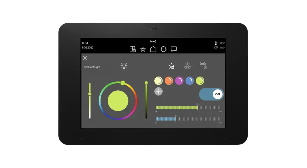
– Graphical user interface for visualisation and operation of KNX devices
– Door communication function only in combination with Siedle Smart Gateway SG 650-.. or SG 150-..
Installation and electrical connection
3.1 Information for electrically skilled persons![]() DANGER
DANGER
Electrical shock on contact with live parts in the installation environment.
Electrical shocks can be fatal.
Before working on the device, disconnect the power and cover live parts in the area!
3.2 Mounting in installation box or appliance box
The Smart Panel is designed for installation in a flush-mounted installation box (ref. no. EBG 24). The Smart Panel adapter is screwed onto the installation box.
Installation boxes from other manufacturers must match the overall dimensions and holes of the adapter and the Smart Panel. (see technical data for overall dimensions)
The installation box must be precisely aligned and mounted flush in the wall.
Alternatively, an appliance box according to EN 60670-1 can be used for mounting the Smart Panel. The Smart Panel adapter is not mounted directly on the appliance box, but on the wall. The recommended depth of the appliance box is approx. 60 mm.
3.3 Mounting the adapter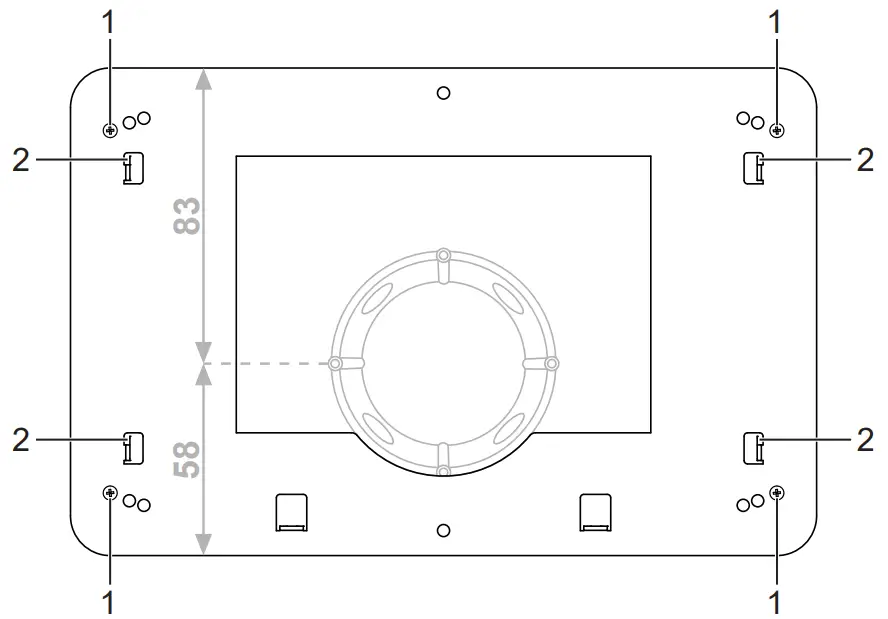
- Adapter locking screw
- Fixing hooks
Mount the adapter on the installation box with a total of four locking screws (1). (fig. 2)
When mounting on an appliance box, the adapter must be mounted on the wall. The adapter must be placed in such a way that the appliance box is located in the indentation of the adapter. In this way, the wall box is located slightly to the bottom of the adapter.
3.4 Connection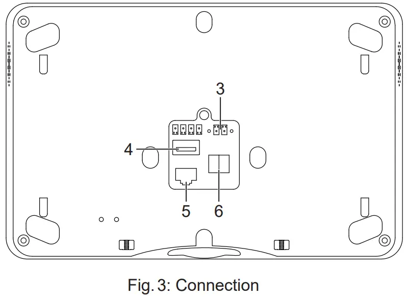 3 Power supply
4 USB
5 LAN/Ethernet
6 KNX bus
Requirements:
– KNX/EIB bus connection
– Power supply via power supply adapter, ref. no.: NT 2415 REG VDC
– For firmware updates, support, IP cameras, door communication or operation via mobile end devices: Ethernet connection
- Connect the power supply (3) and KNX (6). (fig. 3)
- Connect LAN (5) optionally.
![]() Do not connect any other products and loads outside the KNX standard to the bus output. The bus communication could be affected by this.
Do not connect any other products and loads outside the KNX standard to the bus output. The bus communication could be affected by this.
3.5 Mounting the Smart Panel 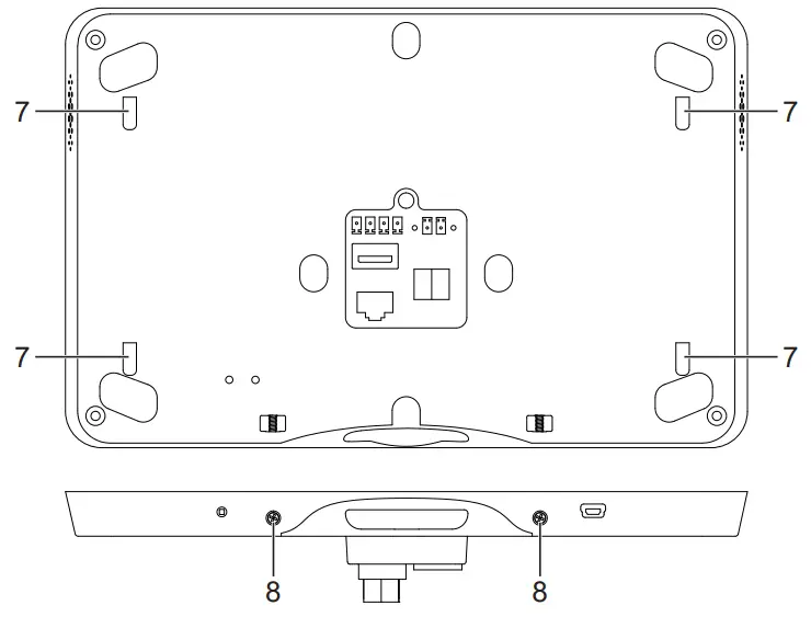 Fig. 4: Mounting the Smart Panel
7 Openings for wall mounting
8 Smart Panel locking screws
• Place the openings for wall mounting (7) on the Smart Panel on the fixing hooks (2) on the adapter. (fig. 2 and fig. 4) To do this, place the openings for wall mounting above the hooks and engage them downwards.
• Fasten the Smart Panel to the adapter on the underside with a total of two locking screws (8). (fig. 4)
Commissioning
4.1 Switching on
After connecting, the device is switched on automatically and the operating system is started.
After the start-up process, you must make the settings for commissioning.
4.2 Settings – Overview of the menu structure
– General
– Language
– Date/time
– Design
– Display
– Advanced
– System password
4.3 Opening the settings
- Select the JUNG logo in the main menu (JUNG Launcher).
Password entry opens. - Enter the system password.
The default system password is “0000“.
The settings open.
4.4 Selecting the language
- Open the settings.
- Select the menu “General”.
- Select the submenu “Language”.
Available languages are displayed. - Select the language.
The language is selected.
4.5 Selecting date and time
- Open the settings.
- Select the menu “General”.
- Select the submenu “Date/time”.
- Make the settings:
– autom. date/time: activated
– autom. time zone: deactivated
– select the time zone (e.g. GMT+2)
– 24-hour format: activated
4.6 Changing the system password![]() The system password grants access to all settings. The user password grants only limited access to the settings.
The system password grants access to all settings. The user password grants only limited access to the settings.
- Open the settings.
- Select the menu “Advanced”.
- Select the submenu “System password”.
The password entry opens. - Enter the current and new system password.
- Confirm passwords with the “OK” button.
The system password is changed.
4.7 Updating the firmware
Prerequisite: Internet connection
- Select the app “System update”.
The app is started. - Select “Search for updates online”.
The firmware is updated automatically.
![]() If there is no Internet connection, a USB storage medium can be used to update the firmware.
If there is no Internet connection, a USB storage medium can be used to update the firmware.
Operation and configuration
The device is operated via pre-installed apps.
The apps must be started via the main menu.
The device is configured via ETS 5 or higher.
The device is planned and designed exclusively with the aid of external project planning software.
You can find detailed information about the operation and configuration of the device in the product documentation. The product documentation is available for downloading on our website.
Cleaning
![]() The cleaning mode is started with the “Screencleaner” app.
The cleaning mode is started with the “Screencleaner” app.
Suitable cleaning agents:
Water, degreaser, glass cleaner, alcohol and isopropyl alcohol Not suitable for cleaning:
Abrasive cloths or harsh detergents
- Start the cleaning mode or switch off the device to lock the touch screen.
- Apply cleaning agent or water to cloth.
Do not apply directly to the device. - Clean the front with a cloth.
Cleaning agent must not get into the device. - Switch the device on again after cleaning or wait for the cleaning mode to end automatically after 30 seconds.
Technical data
| Screen diagonal | 203 mm / 8″ | |
| Resolution | 1280 x 800 (WXGA) | |
| Aspect ratio | 16:10 | |
| Overall dimensions (W x H) | Smart Panel Adapter | 225 x 145 mm 216 x 141 mm |
| Structure height | 16 mm | |
| Installation depth | 22 mm | |
| Power consumption | max. 16 W | |
| Power supply | DC 12 … 32 V SELV via external power adapter | |
| Operating system | Android 6 | |
| Processor | Cortex-A53 | |
| Main memory | 2 GB | |
| Mass storage | 16 GB Flash | |
| Loudspeaker | integrated | |
| Microphone | integrated | |
| USB connection | 1 x USB 2.0 type A | |
| LAN connection | 1 x 10/100/1000 Mbit/s | |
| KNX | KNX connection terminal | |
| Ambient temperature | +30 CC | |
| Atmospheric humidity | 5 … 80 % (no moisture condensation) | |
Accessories
| Power supply adapter | NT 2415 REG VDC |
| Installation box | EBG 24 |
Warranty
The warranty follows about the specialty store in between the legal framework as provided for by law.
![]() ALBRECHT JUNG GMBH & CO. KG
ALBRECHT JUNG GMBH & CO. KG
Volmestraße 1
58579 Schalksmühle
GERMANY
Tel. +49 2355 806-0
Fax +49 2355 806-204
[email protected]
JUNG.DE


