![]()
INSTALLATION QOMS/QOMD
QOMS 60W-750W
 1 CONTROL ZONE
 1 CONTROL ZONE
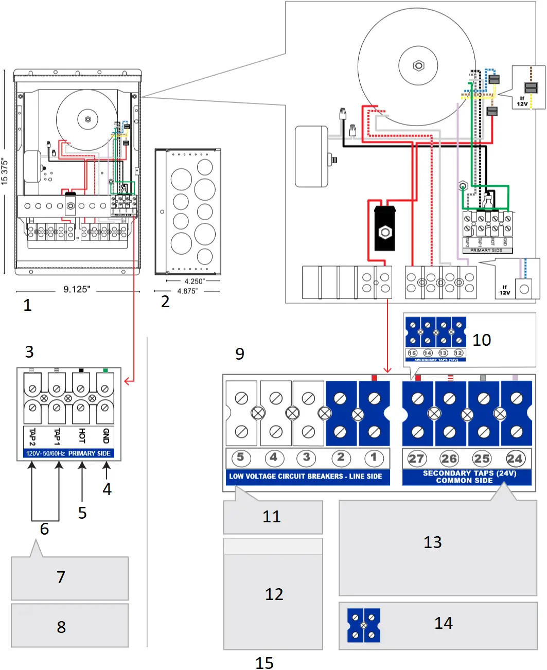
- Front View
- Bottom View
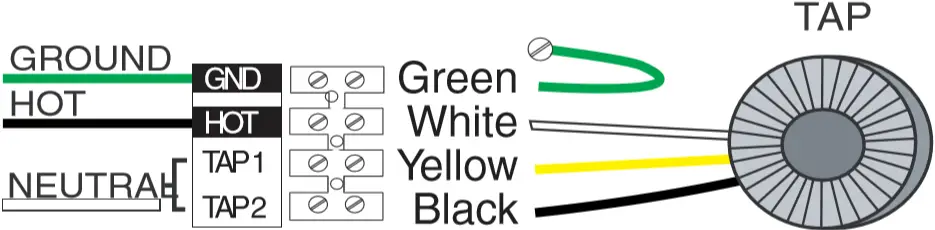
- PRIMARY
Line Voltage - Land Ground
- Land Hot
- Land Neutral
- Chose either tap 1 (switch) or 2 (dimmer; long primary run or low input voltage (115V or less))
- *Must test all voltage readings with a True RMS Voltage Meter when controlled by a dimmer. Do not exceed secondary voltage!
- SECONDARY
Low Voltage - If 12V Taps are
12V, 13V, 14V, 15V - *Up to 5 Sec. Breakers can be used
BKR COLOR 12V 24V 5 A Orange 60w 120w
10 A Red 120w 240w
12.5 A Yellow 150w 300w
15 A Yellow 180w 360w
20 A Blue 240w 480w
25 A Purple 300w 600w- Step 1.
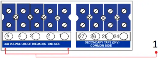
Connect line side or “hot” side of the low voltage connection.
Start with position # 1.
Step 2.
Connect common side to one of the low voltage terminal blocks.
* Repeat step 1 & 2 for every new lead connection. - L.V. Secondary feeds go to a 85 AMP rated terminal block. Each terminal is UL listed to have the following capacity:
6 #14
4 #12
4 #10
2 #8 - *For longer runs you may need to go to a higher tap & or larger wire gauge on secondary side.
QOMD 60W-300W
 2 CONTROL ZONES
 2 CONTROL ZONES
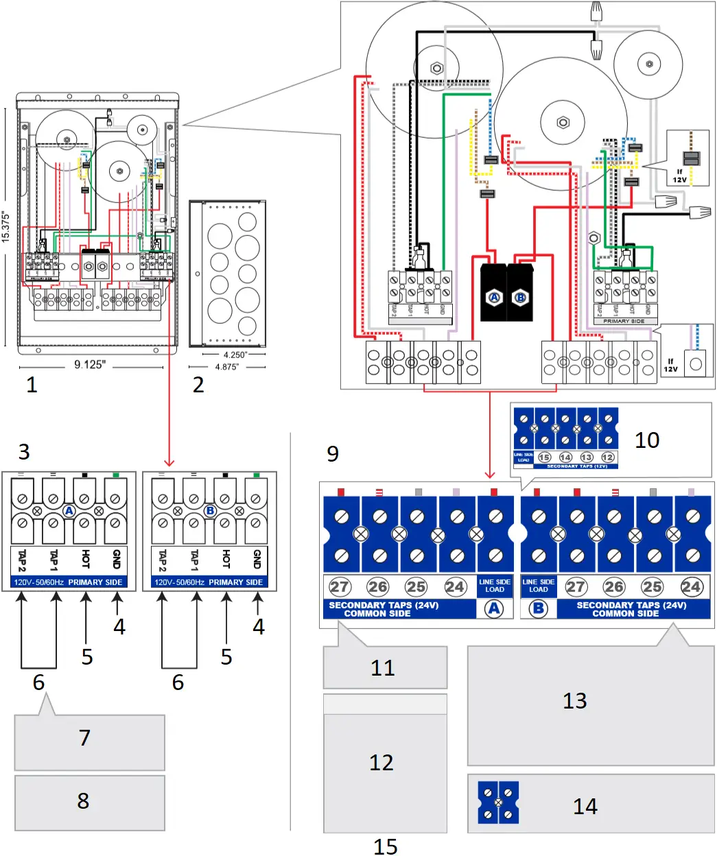
- Front View
- Bottom View
- PRIMARY
Line Voltage - Land Ground
- Land Hot
- Land Neutral
- Chose either tap 1 (switch) or 2 (dimmer; long primary run or low input voltage (115V or less))
- *Must test all voltage readings with a True RMS Voltage Meter when controlled by a dimmer. Do not exceed secondary voltage!
- SECONDARY
Low Voltage - If 12V Taps are
12V, 13V, 14V, 15V - *Up to 5 Sec. Breakers can be used
BKR COLOR 12V 24V 5 A Orange 60w 120w
10 A Red 120w 240w
12.5 A Yellow 150w 300w
15 A Yellow 180w 360w
20 A Blue 240w 480w
25 A Purple 300w 600w- Step 1.
Connect line side or “hot” side of the low voltage connection.
Start with position # 1.
Step 2.
Connect common side to one of the low voltage terminal blocks.
* Repeat step 1 & 2 for every new lead connection. - L.V. Secondary feeds go to a 85 AMP rated terminal block. Each terminal is UL listed to have the following capacity:
6 #14
4 #12
4 #10
2 #8 - *For longer runs you may need to go to a higher tap & or larger wire gauge on secondary side.
Wiring Diagram
120V (60Hz) – 12/24V
PRIMARY SECONDARY
120VAC 12 VAC
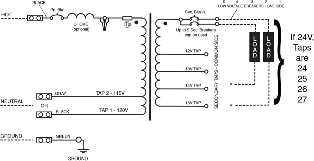
( * ) CONNECT TO ANY TAP
– USE SECONDARY TERMINAL BLOCKS FOR LOAD CONNECTIONS
– DASHED LINES INDICATE ELECTRICAL CONTRACTOR WIRING
– MULTIPLE LOADS CAN BE CONNECTED TO THE SAME OR DIFFERENT TAPS, DEPENDING ON DESIRED OUTPUT VOLTAGE, TO COMPENSATE FOR VARYING LOAD DISTANCES.
230V (50Hz) – 12/24V-![]()
277V (60Hz) – 12/24V
PRIMARY SECONDARY
230/277VAC 12 VAC
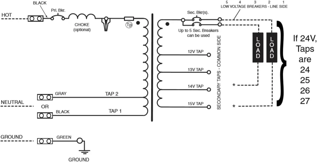
( * )CONNECT TO ANY TAP
– USE SECONDARY TERMINAL BLOCKS FOR LOAD CONNECTIONS
– DASHED LINES INDICATE ELECTRICAL CONTRACTOR WIRING
– MULTIPLE LOADS CAN BE CONNECTED TO THE SAME OR DIFFERENT TAPS, DEPENDING ON DESIRED OUTPUT VOLTAGE, TO COMPENSATE FOR VARYING LOAD DISTANCES.
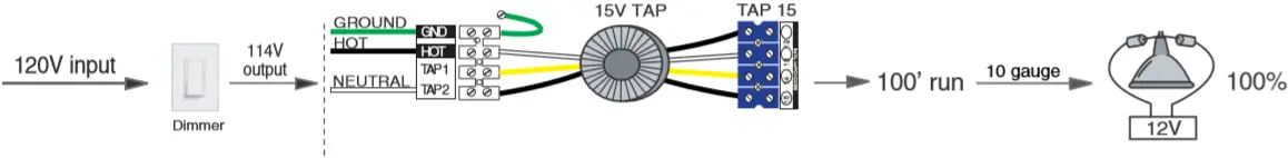
Selecting the Right Tap
 |
| Conclusion: With a simple field adjustment, the contractor was able to recover his voltage drop and light output by switching from Tap 12 to Tap 15. |
A 12V Lamp Operating at 10V = 50 % Light Output!
| Rating | Excellent | Good | Poor | Bad | Very Bad |
Light Output |  |  |  |  |  |
| Lamp Volts | 24.0V | 22.8V | 21.6V | 20.4V | 19.2V |
| Voltage Drop | 0% | -5% | -10% | -15% | -20% |
| Lamp Volts | 12.0V | 11.4V | 10.8V | 10.2V | 9.6V |
| Light Output |  |  |  |  |  |
Rating | Excellent | Good | Poor | Bad | Very Bad |
The Impact of Voltage Drop on Light Output
![]()


*For longer runs you may need to go to a higher tap & or larger wire gauge on secondary side.
* Use a True RMS Volt Meter when a dimmer is used.
(RMS = Root Mean Squared)
- The “line side” of the load is connected to secondary circuit breakers.
[4 AMP – 25 AMP]
Warnings
WARNING
FOR CONDUIT CONNECTION
RISK OF ELECTRIC SHOCK.
Install power unit 5 feet (1.5 m) or more from the pool or spa and 10 feet (3.05 m) or more from a fountain. Where the power unit is installed within 10 feet (3.05 m) of a pool or spa, connect unit to GFCI protected branch circuit.
FOR POWER SUPPLY CORD CONNECTION
RISK OF ELECTRIC SHOCK.
Install power unit 5 feet (1.5 m) or more from the pool, spa, or fountain. Where the power unit is installed (a) indoors within 10 feet (3.05 m) of a pool, spa, or fountain or (b) outdoors, connect power unit to a receptacle protected by a GFCI.
RISK OF FIRE. If installation requires running wire through a building structure, special wiring methods are needed. Contact a qualified electrician.
OUTDOOR CORD – connected unit shall be connected to a GFCI protected hooded flush type cover plate recepticle marked “Wet Location.
DO NOT USE EXTENSION CHORDS.
The main Secondary Wiring is intended for shallow burial – less than 6 inches (152 mm) For Supply connections use wire rated for at least 60C.
* To order additional lengths of wire for connection in the secondary, contact your local distributor or Q-Tran at 203-367-8777 and inquire about Q-Wire.
LISTED  5F78
5F78
LOW VOLTAGE LIGHTING POWER SUPPLY CENTER
- LANDSCAPE LIGHTING POWER UNIT
- SUITABLE FOR WET LOCATION
- SUITABLE FOR INDOOR/OUTDOOR USE
- UL 1838 & 2108 LISTED
- ISOLATION TOROIDAL TRANSFORMER
- USE DIMMERS RATED FOR MAGNETIC LOW VOLTAGE LOADS
- 50/60 CYCLE
- MADE IN THE U.S.A.
For model series:
QOM-60, QOM-100, QOM-150, QOM-300, QOM-500, QOM-600, QOM-750, QOM-2X150, QOM-2X300 and QOM-150/300, all field installed conductors, both primary and secondary, shall have insulation suitable for the highest voltage potential of the equipment.
WIRE TYPE | PRI. WIRE COLOR |
| HOT NEU (TAP 1) NEU (TAP 2) GROUND | BLACK |
BREAKER | MINIMUM AWG | 12V |
| 5A 10A 15A 20A 25A | 14 14 14 12 10 | 60W |
| QOM | ||||||
Model | Input Voltage (V) | Input Current (A) | Frequency | Nominal Output Voltage (VDC) | Max Output Wattage | |
| QOM-60 QOM-60X2 QOM-60/100 QOM-60/150 QOM-60/300 QOM-100 QOM-100X2 QOM-100/150 QOM-100/300 QOM-150 QOM-150X2 QOM-150/300 QOM-300 QOM-300X2 QOM-500 QOM-600 QOM-750 | 120 / 277 120 / 277 120 / 277 120 / 277 120 / 277 120 / 277 120 / 277 120 / 277 120 / 277 120 / 277 120 / 277 120 / 277 120 / 277 120 / 277 120 / 277 120 / 277 120 / 277 | .56 / .25 1.12 / .49 1.48 / .64 1.93 / .84 3.28 / 1.42 .92 / .40 1.84 / .80 2.29 / .99 3.64 / 1.58 1.37 / .59 2.74 / 1.19 4.09 / 1.77 2.72 / 1.18 5.44 / 2.36 4.48 / 1.94 5.32 / 2.30 6.58 / 2.85 | 50/60 50/60 50/60 50/60 50/60 50/60 50/60 50/60 50/60 50/60 50/60 50/60 50/60 50/60 50/60 50/60 50/60 | 12/24 12/24 12/24 12/24 12/24 12/24 12/24 12/24 12/24 12/24 12/24 12/24 12/24 12/24 12/24 12/24 12/24 | 60 60X2 60/100 60/150 60/300 100 100X2 100/150 100/300 150 150X2 150/300 300 300X2 500 600 750 | |
CAUTION: USE ONLY WITH MAXIMUM OUTPUT LOAD PER ABOVE TABLE. This product must be installed in accordance with the applicable installation code by a person familiar with the construction and operation of the product and the hazards involved.
LOW VOLTAGE LUMINAIRE POWER SUPPLY CENTER QOM Series tested to: CLASS: CLASS:
WARNING: RISK OF FIRE. IF INSTALLATION INVOLVES RUNNING WIRE THROUGH A BUILDING STRUCTURE, SPECIAL WIRING METHODS ARE NEEDED. CONSULT A QUALIFIED ELECTRICIAN. | ||||||
© 2023 Q-Tran Inc. All rights reserved | 155 Hill St. Milford, CT 06460 | 203-367-8777 | [email protected] | www.q-tran.com
Specification subject to change. Rev-05-23-23


