![]()
![]() USER MANUAL
USER MANUAL
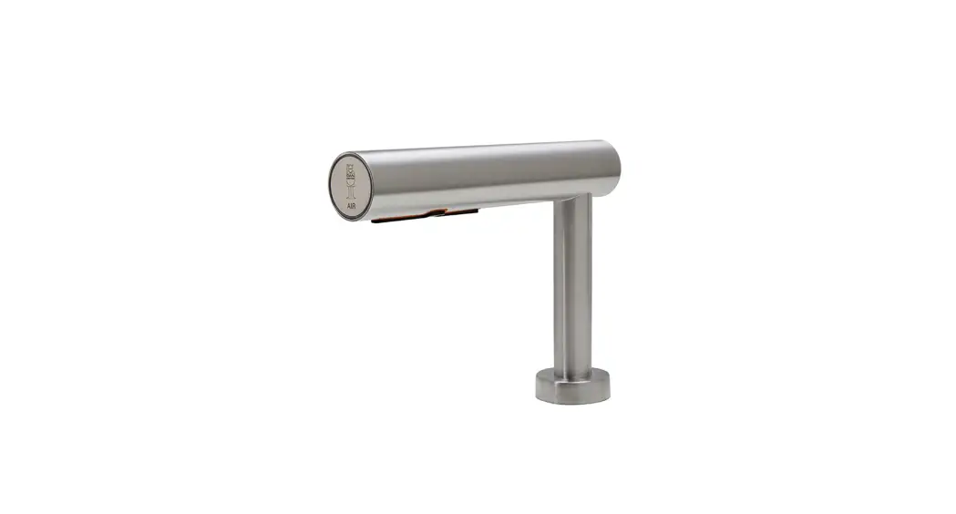
AIRTAP BUILD-IN HAND DRYER
Model: 372-373
372-373 Airtap Build-In Hand Dryer
IMPORTANT!
This product falls within the scope of the WEEE directive on recycling and recovery of waste electrical and electronic equipment.
- This product should not be disposed of with general household waste.
- This product must be reused if possible.
- Contact your local authority for further details.
- This product may also be returned to the manufacturer/retailer for proper treatment, recovery, and recycling.
- Read instructions in full before use.
![]()
DIMENSIONS AND TECHNICAL SPECIFICATIONS
Dimensions
Unit of measurement: mm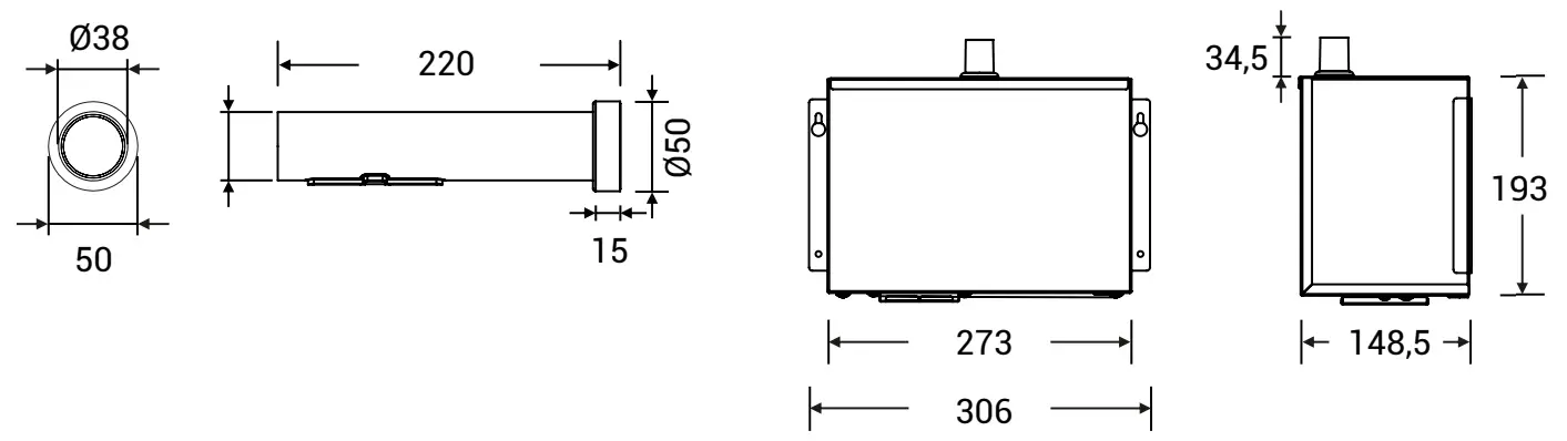
TECHNICAL SPECIFICATIONS
| DESCRIPTION | DATA |
| Operating voltage | 110V-120V, 50/60Hz, 0.84-1.0kW 220V-240V, 50/60Hz, 0.84-1.0kW |
| Air temperature | 55°C — ambient temperature 25°C |
| Airspeed | 93-110 m/s (at air outlet) |
| Motor type | 500W (adjustable) carbon brush, 22.000-29.000 rpm. |
| Motor thermal protector | Auto resetting, the thermostat turns off at 120V at 135°C 240V at 95°C |
| Heating element | 100 – 500W (adjustable) |
| Heating element protection | Auto resetting, the thermostat turns the circuit off at 85°C, thermal fuse turns off at 142°C |
| Drying time | s 10-15 seconds |
| Stand-by power | 0.3-0.4W |
| Sensor type | Infrared, self-adjusting |
| Sensor range | 110-230 mm adjustable. Standard 130 mint 20 mm |
| Protection time | 60 seconds auto shut off |
| IP Class | IP35 |
| Insulation class | Class 1 |
| Net weight | 5.6 kg |
| Gross weight | 8.1 kg |
PRODUCT TYPE / MODEL
372 / 373 Stainless steel, satin finish, AirTap Wall 230V/110V
GENERAL SAFETY INFORMATION
WARNING ![]()
- All units must be equipped with a 3-wire service. Connect the ground wire according to the instructions.
- This product must be installed only by qualified persons.
Use 2.08 mm2 (AWG) NO.14 wiring. - Turn off the power to the unit before servicing or cleaning. All wires must be disconnected.
- Incorrect installation, defective power cords, or failure to properly ground the unit could result in electrical shock or life-threatening injuries.
- Never modify the product.
- Never insert objects into any opening in the product.
- The product is not intended for playing purposes.
- Cleaning and user maintenance must not be carried out by children.
- The product may only be used for the applications described in this manual.
- Do not use any accessories not recommended by the manufacturer.
- The product should be checked on a regular basis. Never use a defective or malfunctioning unit.
- Never make alterations to the product affecting its performance. DAN DRYER’s product warranty does not cover product problems that result from misuse or alteration.
NOTE
Type Y connection: If the power supply cord is damaged, it must be replaced immediately.
Only qualified persons shall be permitted to replace the cord to avoid a hazard. Disconnect the electricity supply cord according to instructions.
This product is not intended for use by persons (inclusive children) with reduced physical, sensory or mental capabilities, or lack of experience and knowledge unless they are supervised or have been given instruction concerning the use of the product by a person responsible for their safety.
Children should be supervised to ensure this product is used correctly.
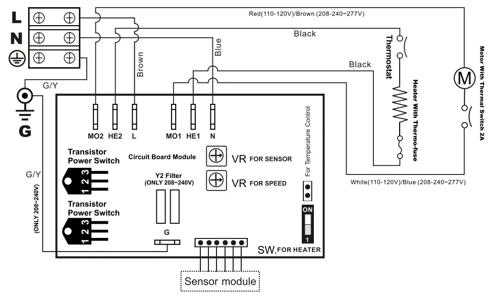
CIRCUIT DIAGRAM
INSTALLATION
Make sure the main breaker is turned off. Installation must be carried out by a qualified person in accordance with applicable standards in the country concerned.
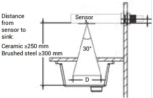
- Check the required distance from the sensor to the sink.
 Sensor field of view:
Object distance 250 mm: D: ≤128 mm
Object distance 300 mm: D: ≤155 mm
Objects within range D may cause unintentional activation. - Check the required distance from the sensor to the sink.

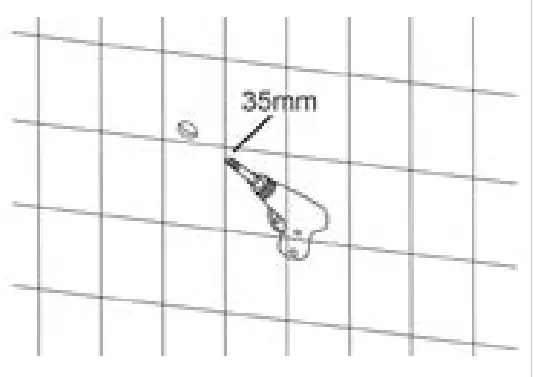
- Mark the desired position on the wall and drill a Ø35 mm diameter hole.

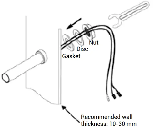
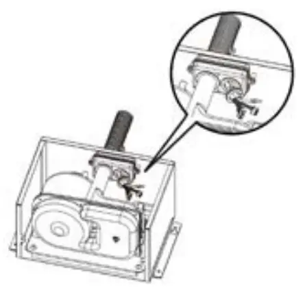
- Installation of the tap:
A) Push the screwed bushing through the hole in the wall
B) Place the gasket, disc, and nut on the threaded coupling of the tap
C) Tighten with the tool, be careful not to overtighten the nut.
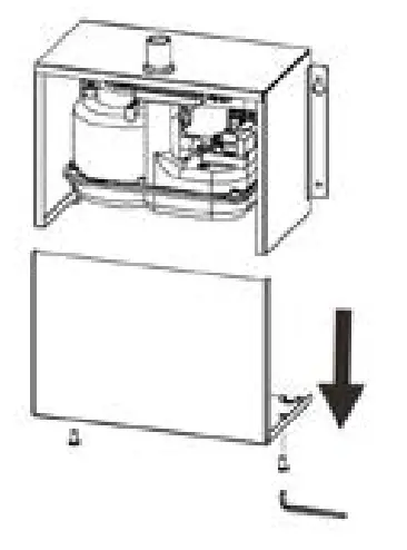
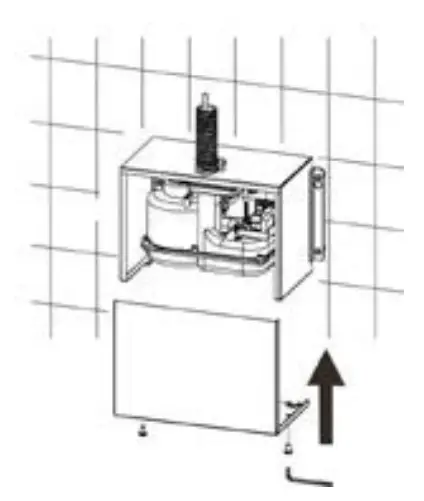
- Unscrew (2) bottom screws and remove the cabinet using the Allen wrench included.

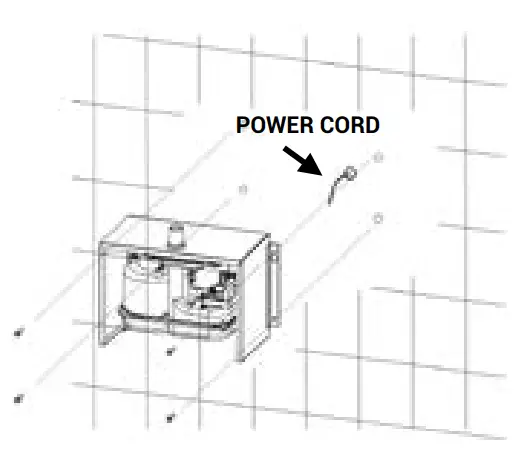
- Mount the unit cabinet to the wall. Insert the power cord through the inlet hole located in the back of the cabinet, or through the premade opening at the bottom of the cabinet. Connect the power cord to the hand dryer. It may be necessary to remove a plate to push the cord through.

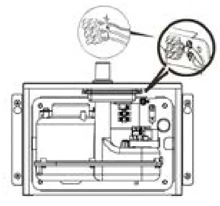
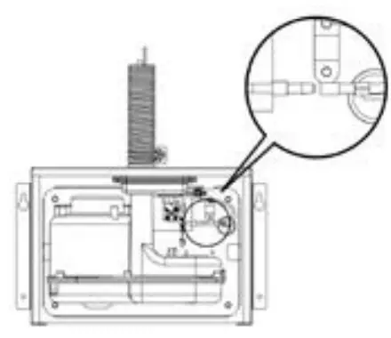
- Connect supply wires to terminal block:
A) Connect phase wire (black or brown) to terminal block ”L”.
B) Connect neutral wire (light blue) to terminal block ”N”.
C) Connect earthing (yellow/green) to terminal block ” ”
”
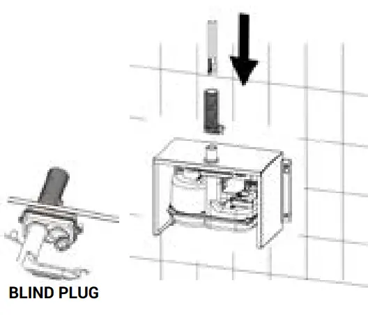
- Remove the end cap from the blind plug. Pull wires and earthing through the Flexi hose and air branch on the motor. Fasten the Flexi hose to the cabinet branch. Attach the opposite end of the flex hose to the branch on tap.

- Close wires and earthing with suitable blind plugs.

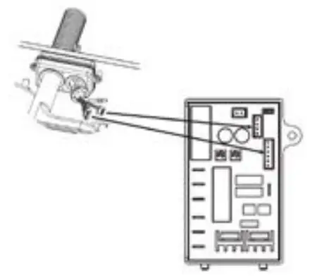
- Connect plugs to timer via respective ports.

- Connect earthing.

- Mount the cabinet front and tighten (2) screws.

- Place the fan for the hand dryer behind the wall.

- Mount the hand dryer fan under the sink.
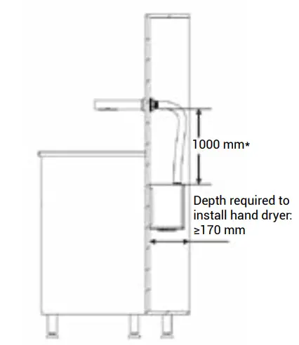
Make sure there is enough space behind the wall to mount the tap. * Standard measures for 1200 mm Flexi hose
 Sensor field of view:
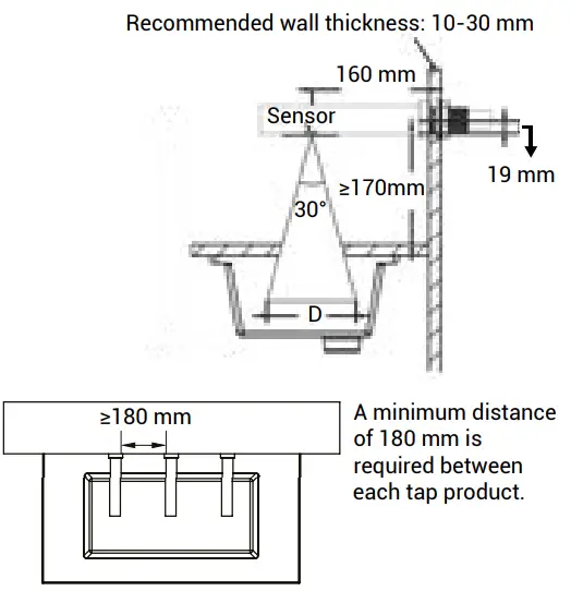
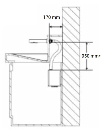 * Standard measures for 1200 mm Flexi hose
IMPORTANT!
- Ensure easy access to maintenance and cleaning of the unit.
- Add extra space (+30 mm) at the air inlet if a HEPA filter should be fitted.
- It is recommended to install a power switch to the hand dryer to ensure easy disconnection of the electricity supply before cleaning and maintenance.
- Do not turn or bend the flex hose too sharply. This will reduce the air velocity and thus increase the drying time.
- Ensure the unit is installed on a solid and stable background.
- If in doubt, contact DAN DRYER
INSTALLATION HEIGHT
PRODUCT APPLICATION
- Shake excess water from hands
- Place hands under the dryer to turn it on
- Place your hands approx. 10-15 cm under the unit
- Move your hands slowly through the airflow from your wrists to fingertips to make the water roll off your hands
- The dryer stops automatically when hands are moved away
LIGHT INDICATOR
| Standby | Solid red light |
| Active | Light changes from blue to red |
RECOMMENDATION:
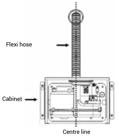
Tolerance for the position of Flexi hose from center line ±2 cm. If tolerance, for any reason, deviates more than ±2 cm on the determined installation position, it must be ensured that the hose is not bent or curved.
A bent or curved hose can cause reduced air velocity and air volume.
CLEANING AND MAINTENANCE
Routine cleaning and maintenance are recommended every 12 months. This may be required more frequently depending on the local conditions.
Carbon brushes are wearing parts and need to be checked more often to prevent damage to the motor.
CLEANING AND MAINTENANCE OF CABINET/MOTOR
- Cut the power
- Unscrew (2) bottom security screws
- Remove cabinet front
- Clean the cabinet inside and remove dust/dirt. Compressed air can be used
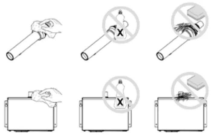
- Do not rinse with running water
- Use a damp cloth and mild cleaning solution. Never use cleaning detergents with an abrasive effect
- Replace the cabinet front and tighten the screws. Ensure not to overtighten screws
CLEANING AND MAINTENANCE OF TAP/SENSOR
- Do not rinse with running water
- Use a damp cloth and mild cleaning solution. Never use cleaning detergents with an abrasive effect
- Clean sensor for dust and dirt to prevent unintentional activation

TIMER SETTINGS
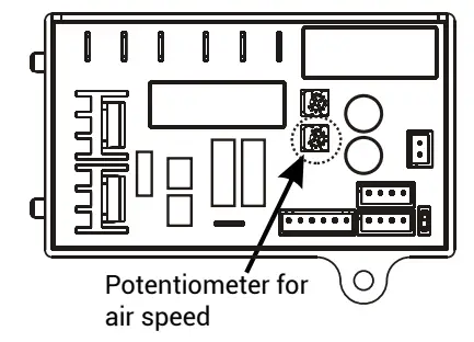
AIRSPEED ADJUSTMENT
- Switch off the power and remove the front cover
- Airspeed is adjusted on the potentiometer
- Use a Phillips screwdriver or flat notch
- Turn clockwise to increase airspeed (+)
- Turn counterclockwise to decrease airspeed (-)
- Be careful not to overturn the adjustment screw
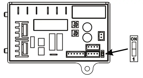
SWITCH FOR HEATING ELEMENT
- Switch off the power and remove the front cover
- The switch for the heating element is placed on a timer.
Use a flat notch to activate/deactivate - Move the switch to ”ON” –> heating element active
- Move the switch to ”1” –> heating element not active
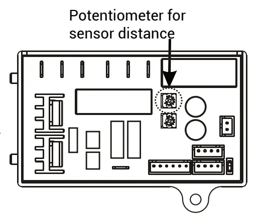
SENSOR RANGE ADJUSTMENT
- Switch off the power and remove the front cover
- Use a Phillips screwdriver or flat notch
- Adjust the sensor activation range on the potentiometer
- The sensor range can be adjusted between 100 mm and 230 mm.
Standard range: 130 mm ± 20 mm - Turn clockwise: Increasing sensor activation range (+)
- Turn counterclockwise: Decreasing sensor activation range (-)
- Sensor activation is affected by the ambient environment, e.g. light and distance to the bottom of the sink
- Be careful not to overturn the adjustment screw
- To ensure the hand dryer functions uninterrupted the activation distance should as a minimum be set at the recommended standard range
TROUBLESHOOTING AND CORRECTIVE ACTIONS
| SYMPTOM | CORRECTIVE ACTION: NEW HAND DRYER |
| The hand dryer does not start | • Check the power supply to the product and ensure the connections at the terminal block are made properly. |
| The hand dryer cycles by itself and runs constantly | • Make sure nothing is obstructing the IR-sensor activation area. • If the problem persists, check the recommended installation height. |
| The hand dryer is very loud and does not run for a complete cycle | • Ensure the power supply is correct • If the timer is damaged, replace both the timer and the sensor. |
| The hand dryer runs randomly and stops before the cycle is finished | • Check the timer and sensor. Replace if required. |
| The hand dryer runs, but the airspeed is low | • Ensure the voltage is correct. • Check the setting of the potentiometer for air speed adjustment (see page 12). |
| SYMPTOM | CORRECTIVE ACTION: USED HAND DRYER |
| The hand dryer does not start | • Check the power supply to the product and ensure the connections at the terminal block are made properly. |
| IR-sensor only detects motion when hands are placed really close to the hand dryer | • Make sure nothing is obstructing the IR sensor. Clean sensor. If the problem persists, disconnect the power and remove the cabinet, taking suitable precautions to avoid shock hazards. • Carefully adjust the sensor range (see paragraph on this subject). • If the problem persists, replace the sensor and timer. |
| The hand dryer blows only cold air during a full cycle | • Disconnect the power. • Remove the cabinet and disassemble the blower/fan unit. Test the thermostat for open circuit. • Check the heating element for defects. Replace defective heating element. |
| LED indicator does not work | • Confirm the unit works properly. If yes, replace the LED circuit board. |
| The hand dryer does not run smoothly | • Check carbon brushes. Replace them if they are worn or damaged. If no faults are detected, replace the motor. |
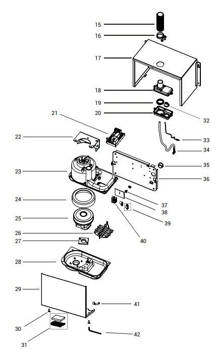
PARTS LIST
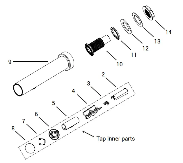
| No. | Description | No. | Description |
| 2 | Sensor housing (upper part) | 23 | Blower housing (upper part) |
| 3 + 4 | Sensor + outlet branch | 24 | Motor rubber (upper part) |
| 5 | Silicone lining | 25 | Motor |
| 6 | Holder for LED circuit board | 26 | Heating element |
| 7 | LED circuit board | 27 | Motor rubber (lower part) |
| 8 | End piece | 28 | Blower housing (lower part) |
| 9 | Tap | 29 | Cabinet (front part) |
| 10 | Threaded bushing | 30 | Hexagonal security screw |
| 11 | Small rubber gasket | 31 F | filter set (filter and holder) |
| 12 | Large rubber gasket | 32 | Rubber bush |
| 13 | Stainless steel disc | 33 | Earthing |
| 14 | Nut | 34 | Sensor cable |
| 15 | Flexi hose (30 cm) | 35 | Nylon bushing |
| 16 | Clamp for flex hose (2 pcs.) | 36 | Backplate |
| 17 | Stainless steel cabinet (back) | 37 | Earthing screw |
| 18 | Mounting cap | 38 | Insulation mylar |
| 19 | Gasket for wire set | 39 | Cable clamp |
| 20 | Mounting cap (lower part) | 40 | Terminal |
| 21 | Timer | 41 | Cable protection |
| 22 | Gasket for mounting cap | 42 | Allen screw |
DAN DRYER A/S
Alsikevej 8
DK – 8920 Randers NV
Tel: +45 8641 5711
Email: [email protected]
dandryer.com


