![]() 192-731 Powers Controls Electrical Finish Plate Installation Template
192-731 Powers Controls Electrical Finish Plate Installation Template
Instruction Manual Installation Instructions
Document No. 129-103
March 16, 2022
192-731 Powers Controls Electrical Finish Plate Installation Template
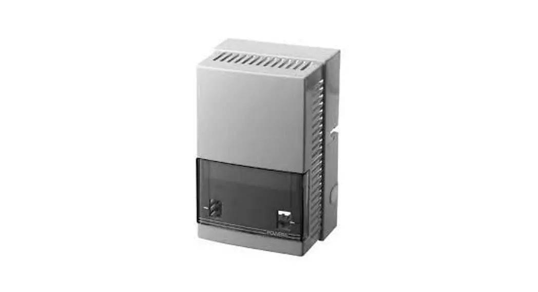
Powers® Controls Electrical Finish Plate
Installation Template for Pneumatic/Electronic Sensors
Product Numbers
| Kit Number | Description | Finish | Electrical Rough-In Box | |
| Size | Reference* | |||
| 192-731 | 1 Sensor | Stainless Steel | 2 Ganq — 2-1/2 inch deep | Appleton M2-250 |
Installation
- Use this wall cutout template (see Page 2) if an electrical wall-box is not required. Refer to and follow local or National Electrical Code requirements.
- Finish plates may be installed using one of the following three methods:
a. Electrical rough-in box, see Table 1. No other hardware is required (screws are included with finish plate).
b. Plastic anchors for use with No. 6 × 1-1/4 inch flat-head screws (anchors and screws not included with finish plate).
c. Finished drywall mounting clips and screws (mounting clips and screws not included). Order Product Number 182-685 (package of 20 clips each). - After wall cutout is made and tubing/wiring is pulled into position, follow these procedures: a. Remove sensor cover from sensor chassis (not applicable to pneumatic switches or pneumatic thermostats).
b. Mount sensor wallplate to finish wallplate.
c. Mount pneumatic switch to finish wallplate.
d. Wire electrical switch, mount to wallbox or to wall when required.
e. Attach pneumatic tubing to sensor chassis or wallplate plug-in adaptors. (Do not forget the restrictor on applicable sensors).
f. Attach finish plate to wallbox or to wall (plastic anchors or mounting clips), being careful not to bend or kink the pneumatic tubing. - When using an electrical wallbox for pneumatic switches, provide a box with a minimum depth of 3-1/2 inch (89 mm) for clearance of fittings, tubing, and the switch body.
The installation is now complete.
Item Number: 129-103, Rev. EA
Information in this publication is based on current specifications. The company reserves the right to make changes in specifications and models as design improvements are introduced. Powers is a trademark of Siemens Industry, Inc. © 2012-2022 Siemens Industry, Inc.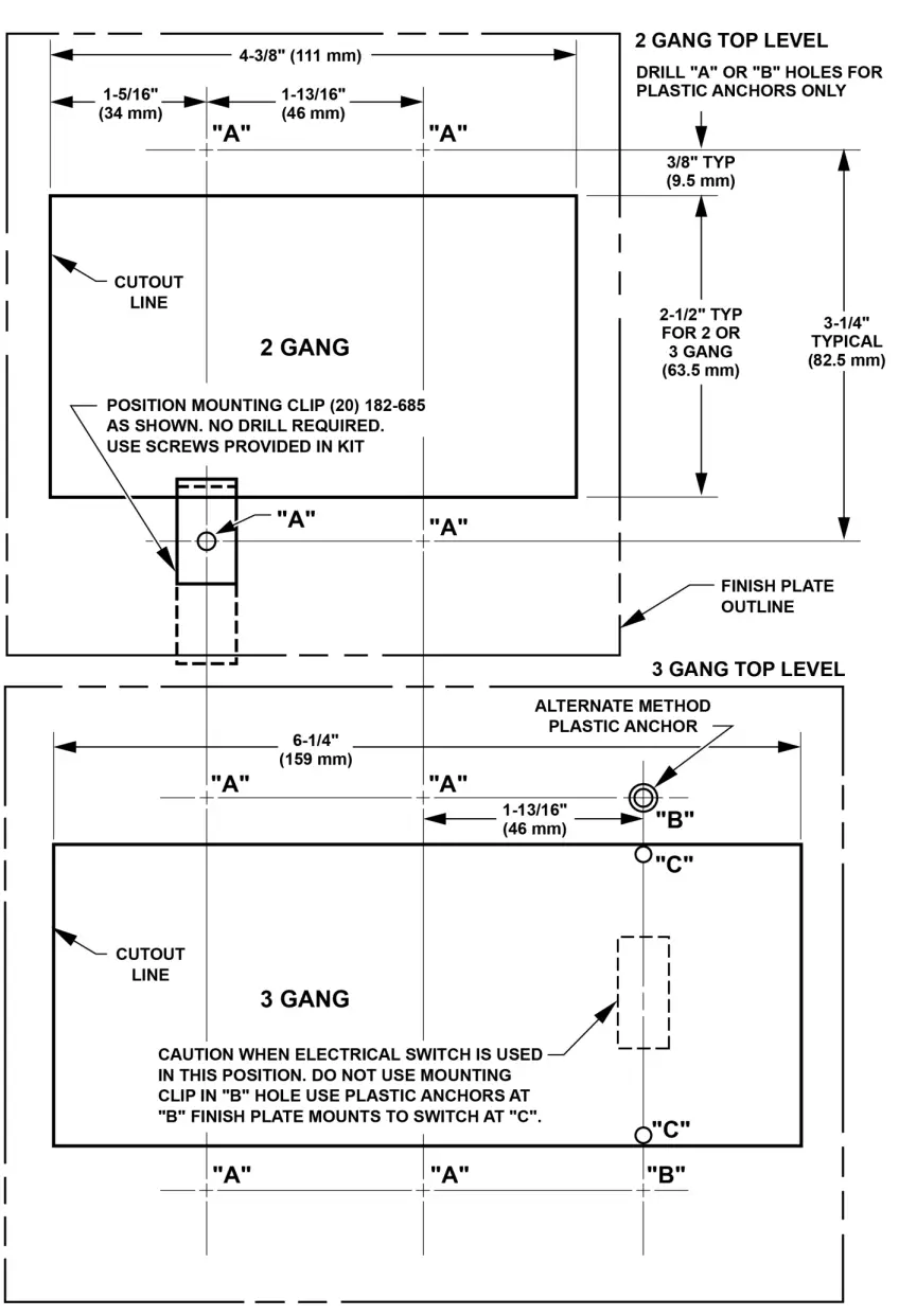
![]() Siemens Industry, Inc.
Siemens Industry, Inc.
Smart Infrastructure 1000 Deerfield Parkway
Buffalo Grove, IL 60089-4513
USA +1 847-215-1000
Your feedback is important to us.
If you have comments about this document
please send them to [email protected]
Document No. 129-103
Printed in the USA


