 HEX3653 FM Radio Receiver
User Manual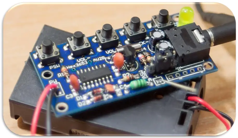
HEX3653 FM Radio Receiver Module D.I.Y. Kit
(for Advanced Users)
Description:
This FM receiver is a D.I.Y. kit that requires soldering through-hole and surface mount components on a double-sided printed circuit board. It is designed for users with advanced soldering tools and skills. You must solder the IC pins on the top surface and the rest of the components’ leads on the bottom side of the board. The assembly process should take anywhere between 30 minutes to an hour. This kit should help you to practice your hands-on skills including your soldering techniques.
The module is based on a HEX3653 IC which is essentially an FM radio chip that can receive modulated FM signals with a frequency range of 76 to 108MHz. The integrated circuit of this module will allow you to increase/decrease the volume, seek channels on the FM band, and use an external antenna if needed. The filters will separate the desired radio frequency signal from all other signals picked up by the antenna. The amplifier is used to increase the power of the signal for the demodulation process of the FM composite signal. For a more in-depth description of how this FM receiver works refer to section 5 (page 5).
Specification:
- Required Input Voltage: 2x AA 1.5V Batteries ( 3V)
Bill of Materials
This package includes 25 components which are listed below along with their labels:
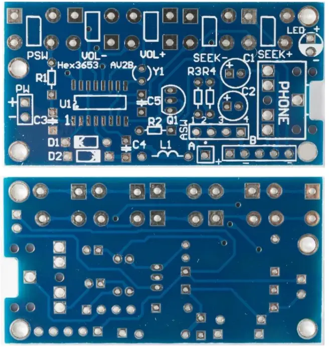 | 1) 1x PCB Printed Circuit Board (doubled-sided, tin-plated, blue solder mask, white silkscreen) |
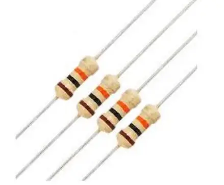 | 2) 4x 10k ¼ Watt Resistors R1, R2, R3, R4 |
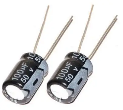 | 3) 2x 100µF 50V Electrolytic Polarized Capacitors C1, C2 |
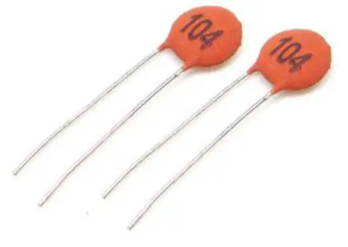 | 4) 2x 100nF Ceramic Capacitors C3, C5 |
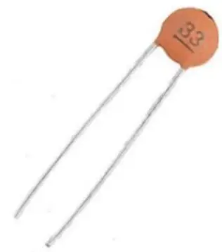 | 5) 1x 33pF Ceramic Capacitors C4 |
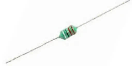 | 6) 1x 10µH Lead Axial Inductor – L1 |
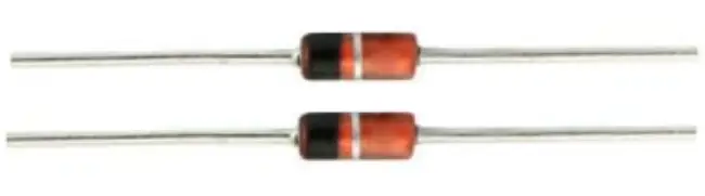 | 7) 2x 1N4148 Switching Signal Diodes D1, D2 |
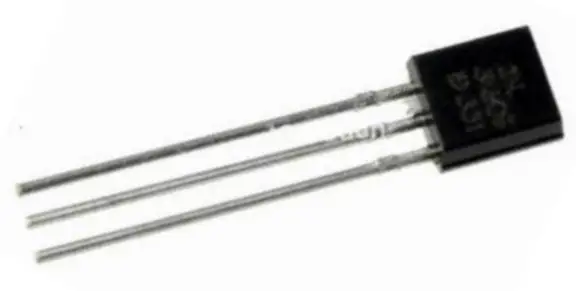 | 8) 1x SS8050 NPN Transistor Q1 |
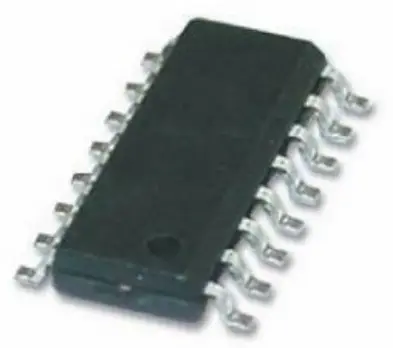 | 9) 1x HEX3653 SOIC IC chip U1 |
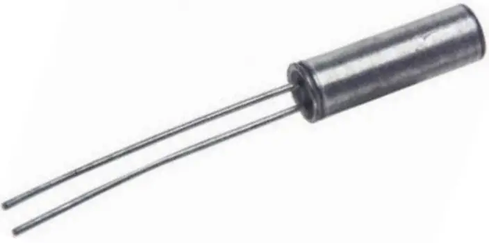 | 10) 1x 32KHz Round Crystal Y1 |
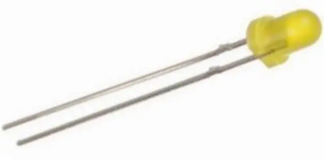 | 11) 1x 3mm Yellow LED LED |
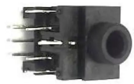 | 12) 1x 3.5mm Stereo Audio Socket PHONE |
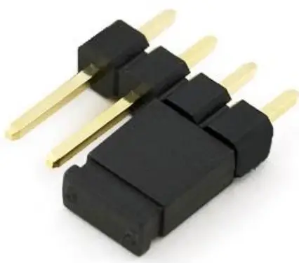 | 13) 1x Single-row 4-pin Header with jumper ASW |
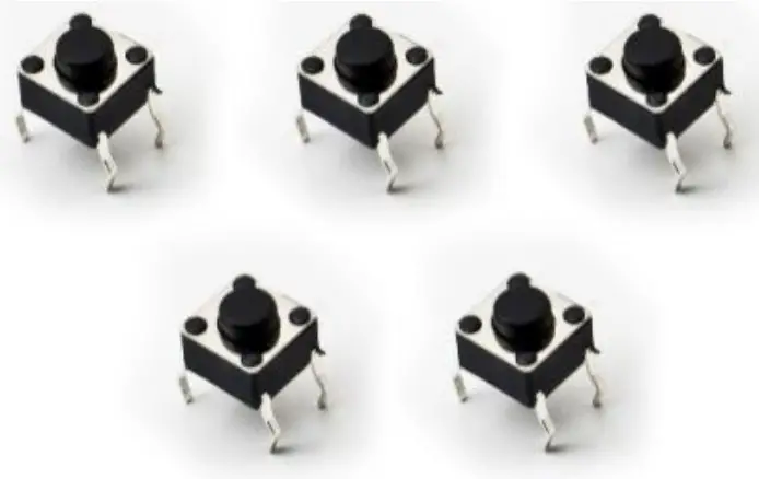 | 14) 5x Mini Push Buttons PSW, VOL-, VOL+, SEEK-, SEEK+ |
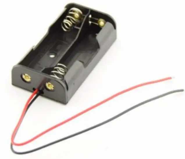 | 15) 1x 2-AA Series Battery Holder NOT LABELED *Batteries are not included* |
Circuit Diagram:
The following figure represents how the HEX3653 FM Receiver circuit is constructed: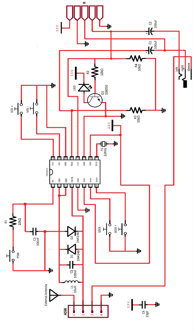
How It Works:
The kit that you’ve purchased is essentially a stereo auto-scanning FM receiver based on a single HEX3653 chip that uses push buttons to adjust the volume, scan FM channels, and power ON/OFF. It requires two AA 1.5V batteries to power up; therefore, the operating voltage is around 3V in case an external power supply is used.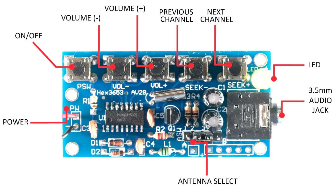 The circuit provides audio filters using capacitors and resistors (RC filters) to provide a clear and high-quality sound when receiving a strong FM signal. The ASW (Antenna Switch) header is used to choose the antenna. As radio waves are intercepted by the antenna, electrons in the antenna begin to vibrate up and down. The antenna signal originates at the header pins. Pin 1 on the header is for the connection of an external antenna. Pin 2 is connected back to the HEX3653 chip. Pin 3 is connected to the 3.5mm audio socket antenna shield which allows the auxiliary cord to serve as an antenna. By adding the jumper sleeve over pins 2 and 3, the auxiliary cord is used as an antenna. Adding the jumper sleeve over pin 1 and pin 2 allows us to use an external antenna. The remaining fourth header pin is connected to the ground. Since our configuration has the jumper sleeve placement on pin 2 and pin 3, the auxiliary cord or headphone cord is acting as the antenna, so the antenna signal is being received at the headers from pin 3 and passed to pin 2.
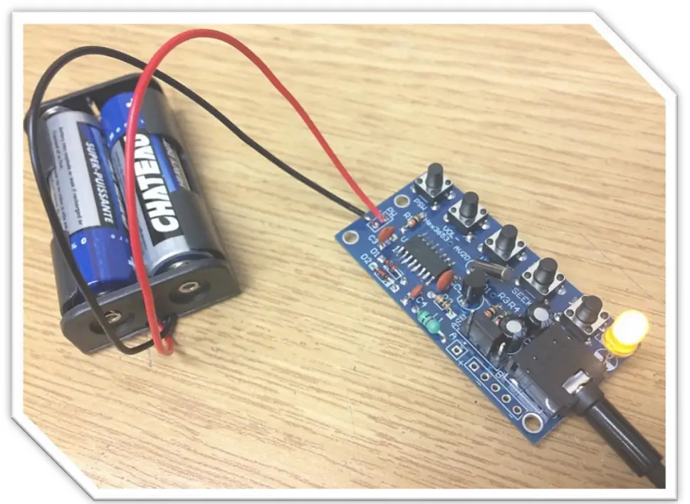 From the second pin of the ASW header, the alternating current passes through the 10µH inductor (L1) and the 33pF capacitor (C4) as well as the 1N4148 diodes (D1 & D2) in order to limit the pin voltage to about 0.3V to protect the chip from damage. This signal enters the HEX3653 chip at pin 4 (FM IN). This incoming signal is then compared to the reference signal received from the onboard antenna which is a 32KHz crystal connected to pin 9 (RCLK).
The RCLK signal is controlled by the SEEK+ and SEEK- push buttons. The tuning, detection, and amplification of the signal is all done inside the HEX chip.
The audio output is at pin 12 (Lout) and 13 (Rout). Both signals are connected to the 10K resistors (R2, R3 and R4) and the DC blocking 100µF electrolytic capacitors (C1 & C2) to prevent any DC signals with 0Hz frequency from passing through and causing distortion. This RC network (resistor-capacitor) also functions as a high-pass filter that only allows the audio signal to pass through and removes any unwanted noise.
The DC bias of the left and right signals (Lout & Rout) is fed to the Q1 transistor to turn the LED on when the FM receiver is in use. The left and right signals (Lout & Rout) are terminated at the 3.5mm audio socket where you can plug in your small speakers or a headphone. These audio signals are also connected to the through-hole connectors (labeled “B”) on the circuit board so you can essentially integrate this module into other applications.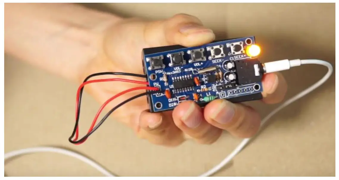
Assembly:
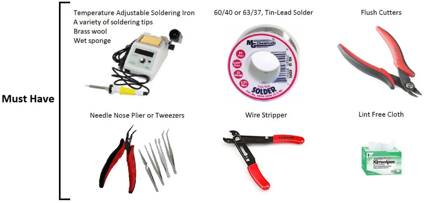
- In order to assemble the module, you need the following tools:
 *It is recommended to have some isopropyl alcohol and a fine soldering brush handy to clean off the excess flux on the circuit board when soldering.
 *ATTENTION* DO NOT USE RUBBING ALCOHOL, IT WILL DAMAGE THE COMPONENTS.
 - Open the package and verify the components. (refer to section
- Bill of Materials on pages 3-4 for this step) 3) Lay down the IC, resistors, capacitors, push buttons, audio sockets, and other components in a safe spot on your workbench and proceed to the next step. *ATTENTION* SURFACE MOUNT COMPONENTS ARE VERY SMALL. DO NOT LOSE THEM. IT IS RECOMMENDED TO USE YOUR PLIERS WHEN YOU ARE HANDLING THEM.
- *OPTIONAL* It is best practice to check component values using proper equipment (i.e. using a Digital Multimeter to verify the ohmic value of the resistors) before proceeding to the next step. You can also verify that the LED is functional before soldering it onto the board.
- Prepare your soldering tools.
a) Use an appropriate tip for the application (through-hole, surface mount, etc.). Also, make sure the soldering tip is clean. Gently use brass wool or a brush to clean the tip when needed. Another way of cleaning the soldering tip is to use a wet sponge. *ATTENTION* IT IS RECOMMENDED TO USE A FLATHEAD TIP TO SOLDER SMD IC CHIPS. SIMPLY ADD SOLDER TO THE FLAT SURFACE AREA ON THE TIP AND SOLDER 3-4 PINS AT A TIME. USE A MEDIUM TIP TO SOLDER THE REST OF THE COMPONENTS.
b) The soldering iron temperature depends on the type of solder used. If you are using a typical 60/40 lead solder, the temperature should be set depending on the thickness anywhere between 370 to 500 °F (187 to 260 °C). If you are using a lead-free solder, increase the above temperatures by 40 to 70 °F (5 to 20 °C). *ATTENTION* HIGHER TEMPERATURES WILL DAMAGE THE COMPONENTS ALONG WITH THE CIRCUIT BOARD. *ATTENTION* DO NOT TOUCH THE SOLDERING IRON TIP WHEN IT IS HOT.
c) It is recommended that you clean the board with a brush, isopropyl alcohol, and lint-free cloth to get rid of any residue, glue or dirt. This way the solder will create a better joint with the copper pads.
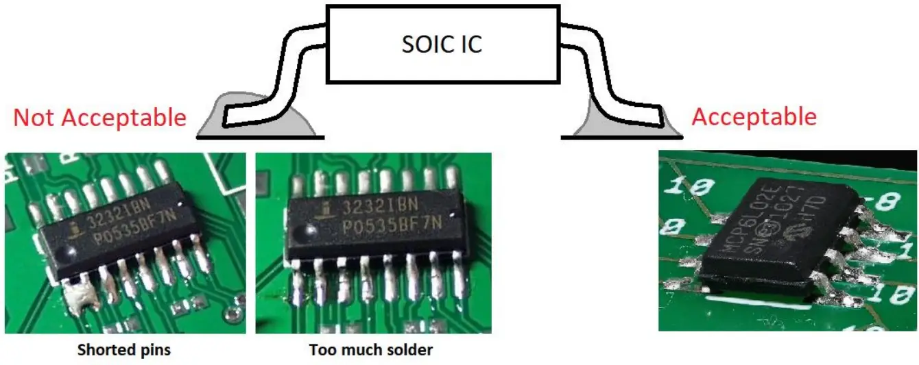
d) Have your flush cutter, needle nose plier or tweezers handy. e) Having a roll of paper tape helps you to keep the components in place when soldering on the bottom side of the board. *ONLY FOR THROUGH-HOLE COMPONENTS* f) Have a rosin flux pen or paste handy. Adding flux to the pads before soldering the component makes the process easier by letting the melted solder to flow better on the pad and create a better joint. *ATTENTION* SOLDERING SHOULD BE DONE IN A VENTILATED AREA. BREATHING SOLDER FUMES WILL HARM YOU. - Start the assembly by soldering the SMD HEX3653 chip (U1). Depending on your level of comfort and skills, you can add an appropriate amount of solder to all sixteen pads then place the chip on the board and heat up the pins onto the previously added solder until the IC chip leads and the solder fuse together.
Otherwise, add some solder to the pads on one side of the chip, place the chip on the board and heat up the pins onto the solder. Once the chip is secured, solder the rest of the pins on the opposite side using your flathead tip. Remember to use your set of pliers or tweezers to place an SMD component in its designated location on the PCB. Refer to the guide below as a reference to inspect the quality of your soldered joints.
- Once the HEX3653 chip is soldered on the PCB, place the resistors (R1, R2, R3 & R4), the ceramic capacitors (C3, C4 & C5), the inductor (L1) and the diodes (D1 & D2) on the board and solder them from the bottom side. You can solder these through-hole components one by one or all at once.

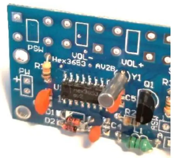
- Place the transistor (Q1) and the crystal (Y1) on the board and solder them from the bottom side.

- Insert the LED and the electrolytic (polarized) capacitors (C1 & C2) on the board and solder them from the bottom side.

- Next, insert the push buttons (PWR, Vol-, VOL+, SEEK- & SEEK+) onto the board and solder them from the bottom side.

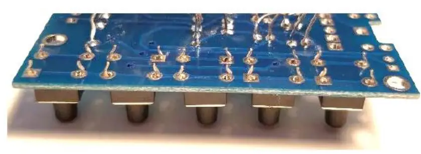
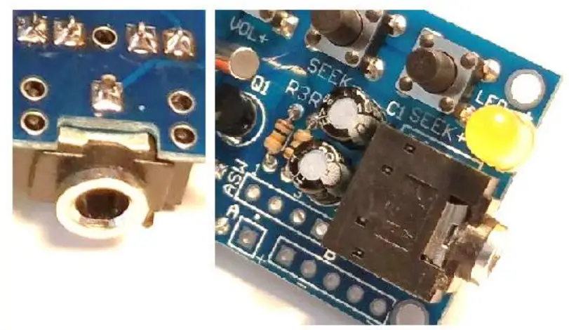
- Insert the 3.5mm audio socket (PHONE) onto the board and solder the pins that are inserted in the square-shaped pads. There are five of them.

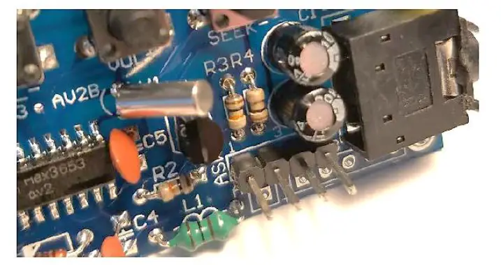
- Finally, place the single-row 4-pin header (ASW) on the board and solder it from the bottom side. Remember that the longer leads should be on the top as seen in the picture.

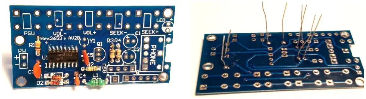
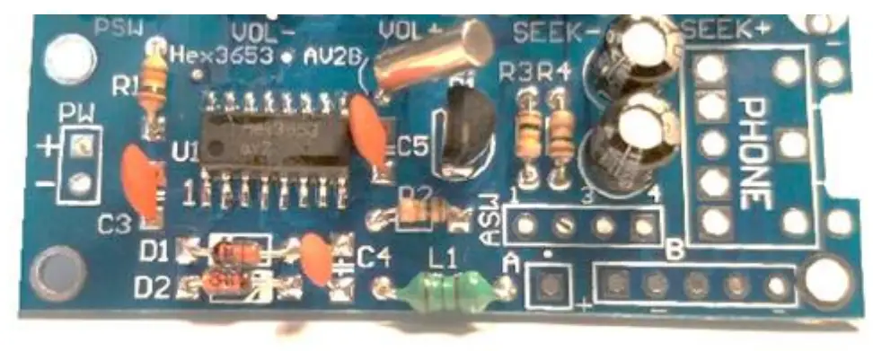
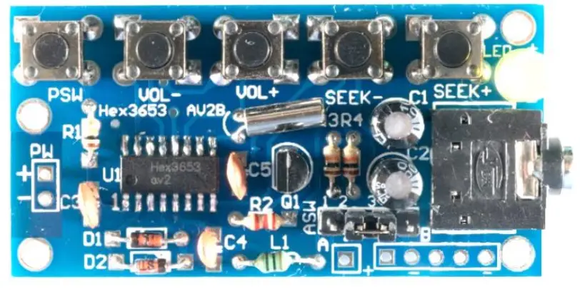
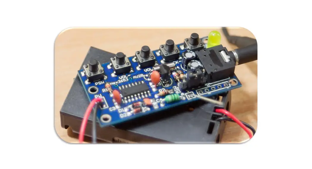
- Your circuit board should look like this if you have proceeded up to step 12.

- Using your brush, isopropyl alcohol, and lint-free cloth, clean the board thoroughly and make sure no flux residue is left.
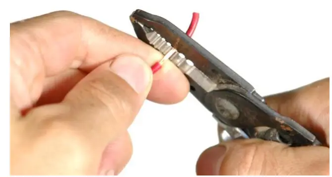
- Using a wire stripper, strip the positive (red) and the negative (black) wires of the AA battery holder

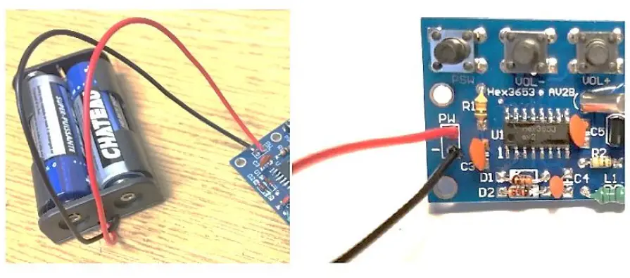
- Insert the positive and the negative wires of the battery holder in the appropriate hole on the board (PW) and solder them from the bottom side. Insert two AA 1.5V batteries

- Place the header jumper between pin 2 and 3 on ASW. Plug in your headphone/earphones and turn ON the FM receiver by pressing the PSW push button once
- You have completed the assembly of your module.

 *It is recommended to have some isopropyl alcohol and a fine soldering brush handy to clean off the excess flux on the circuit board when soldering.
 *ATTENTION* DO NOT USE RUBBING ALCOHOL, IT WILL DAMAGE THE COMPONENTS.
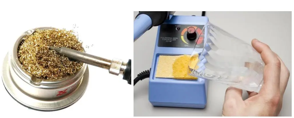 *ATTENTION* IT IS RECOMMENDED TO USE A FLATHEAD TIP TO SOLDER SMD IC CHIPS. SIMPLY ADD SOLDER TO THE FLAT SURFACE AREA ON THE TIP AND SOLDER 3-4 PINS AT A TIME. USE A MEDIUM TIP TO SOLDER THE REST OF THE COMPONENTS.
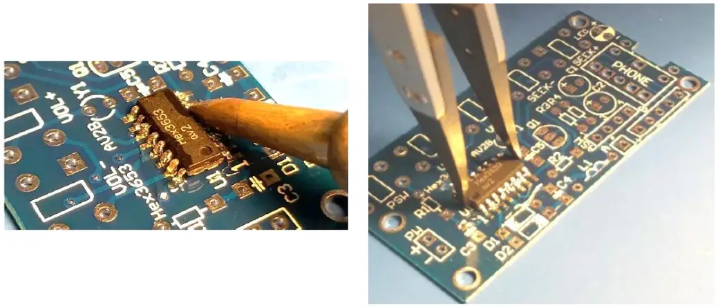 Refer to the guide below as a reference to inspect the quality of your soldered joints.