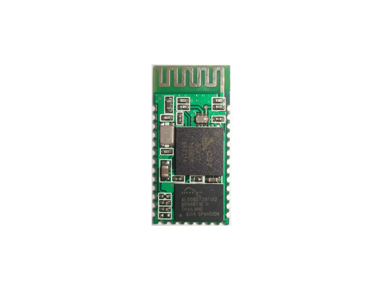
Banggood HC-05
Overview
This module supports UART, USB, SPI, PCM, SPDIF and other interfaces, and supports SPP Bluetooth serial port protocol, which has the advantages of low cost, small size, low power consumption, high sensitivity of sending and receiving.
Feature
- Bluetooth V2.0+EDR
- Bluetooth Class 2
- Built-in PCB RF antenna
- Built-in 8Mbit Flash
- Support SPI programming interface
- Support UART, USB, SPI, PCM and other interfaces
- Support master and slave
- Support software control master-slave module
- 3.3V power supply
- Passed REACH, ROHS certification
Application areas
- Bluetooth car handsfree
- Bluetooth GPS
- Bluetooth PCMCIA, USB Dongle
- Bluetooth wireless data transmission;
- Industrial remote control, telemetry;
- POS system, wireless keyboard, mouse;
- Traffic, underground positioning, alarm;
- Automated data acquisition system;
- Wireless data transmission; banking system;
- Wireless data collection;
- Building automation, security, wireless monitoring of equipment room, access control system;
- Smart home, industrial control;
- Vehicle inspection equipment;
- Interactive program voting equipment for television stations;
- Government street lamp energy saving equipment
- Wireless LED display system
- Bluetooth joystick, Bluetooth gamepad
- Bluetooth printer
- Bluetooth remote control toy
Physical characteristics
| Operating Frequency Band | 2.4GHz ISM band |
| Bluetooth Specification | V2.0+EDR |
| Output Power Class | Class 2 |
| Operating Voltage | 3.3V |
| Host Interface | USB 1.1/2.0 or UART |
| Audio Interface | PCM interface |
| Flash Memory Size | 8Mbit |
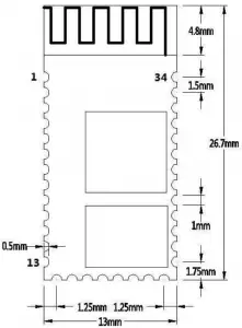
| Dimension | 27mm (L) x 13 (W) mm x 2mm (H) |
Electrical characteristics
| Absolute Maximum Ratings | ||
| Rating | Min | Max |
| Storage temperature | -40℃ | +150℃ |
| Supply voltage: VBAT | -0.4V | 5.6V |
| Other terminal voltages | VSS-0.4V | VDD+0.4V |
| Recommended Operating Conditions | ||
| Operating Condition | Min | Max |
| Operating temperature range | -40℃ | +150℃ |
| Guaranteed RF performance range(a) | -40℃ | +150℃ |
| Supply voltage: VBAT | 2.2V | 4.2V(b) |
Power consumption
| Operation Mode | Connection Type | UART Rate(kbps) | Average | Unit |
| Page scan | – | 115.2 | 0.42 | mA |
| ACL No traffic | Master | 115.2 | 4.60 | mA |
| ACL With file transfer | Master | 115.2 | 10.3 | mA |
| ACL 1.28s sniff | Master | 38.4 | 0.37 | mA |
| ACL 1.28s sniff | Slave | 38.4 | 0.42 | mA |
| SCO HV3 30ms sniff | Master | 38.4 | 19.8 | mA |
| SCO HV3 30ms sniff | Slave | 38.4 | 19.0 | mA |
| Standby Host connection | – | 38.4 | 40 | µA |
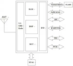
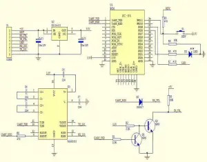
Functional block diagram
Application circuit diagram
Pin function description
| PIN | NAME | TYPE | Function |
| 1 | UART-TX | CMOS output | Serial data output |
| 2 | UART-RX | CMOS input | Serial data input |
| 3 | UART-CTS | CMOS input | Serial port clear send |
| 4 | UART-RTS | CMOS output | Serial port request to send |
| 5 | PCM-CLK | Two way | PCM clock |
| 6 | PCM-OUT | CMOS output | PCM data output |
| 7 | PCM-IN | CMOS input | PCM data input |
| 8 | PCM-SYNC | Two way | PCM data synchronization |
| 9 | AIO(0) | Two way | Programmable analog input and output |
| 10 | AIO(1) | Two way | Programmable analog input and output |
| 11 | RESETB | CMOS input | Reset/reset button |
| 12 | 3.3V | power input | +3.3V power supply |
| 13 | GND | Ground | Ground |
| 14 | NC | Output | NC (please hang) |
| 15 | USB-DN | Two way | USB data negative |
| 16 | SPI-CSB | CMOS input | SPI chip select |
| 17 | SPI-MOSI | CMOS input | SPI data input |
| 18 | SPI-MISO | CMOS output | SPI data output |
| 19 | SPI-CLK | CMOS input | SPI clock port |
| 20 | USB-DP | Two way | USB data is positive |
| 21 | GND | Ground | Ground |
| 22 | GND | Ground | Ground |
| 23 | PIO(0) | Two way | Programmable input/output port (0) |
| 24 | PIO(1) | Two way | Programmable input/output port (1) |
| 25 | PIO(2) | Two way | Programmable input/output port (2) |
| 26 | PIO(3) | Two way | Programmable input/output port (3) |
| 27 | PIO(4) | Two way | Programmable input/output port (4) |
| 28 | PIO(5) | Two way | Programmable input/output port (5) |
| 29 | PIO(6) | Two way | Programmable input/output port (6) |
| 30 | PIO(7) | Two way | Programmable input/output port (7) |
| 31 | PIO(8) | Output | Status indicator LED port 1 |
| 32 | PIO(9) | Output | Status indicator LED port 2 |
| 33 | PIO(10) | Two way | Programmable input/output port (10) |
| 34 | PIO(11) | Input | Module state switching pin, High level -> AT command responds to working status; Low level or floating -> Bluetooth normal working status. |
Dimensions
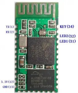
Serial port module pin definition
- PIO(8) connects to the LED to indicate the working status of the module. The module flashes after power-on, and the different states flash differently.
- PIO (9) is connected to the LED to indicate that the module is successfully
connected. After the Bluetooth serial port is successfully connected, the LED is on. - PIO (11) module state switching pin, high level –> AT command response working state, low level or floating –> Bluetooth normal working state.
- The reset circuit is already on the module and reset when the power is turned back on. 12.
Steps to set the master mode
- PIO (11) is set high.
- Upon power-on, the module enters the AT command response state.
- HyperTerminal or other serial port tool, set baud rate 38400, data bit 8 bits, stop bit 1 bit, no parity bit, No flow control.
- The serial port sends the character “AT+ROLE=1\r\n” and successfully returns “OK\r\n”, where \r\n is a carriage return line feed.
- PIO (11) is de-asserted, re-powered, the module is the main module, and the slave module is automatically searched to establish a connection.
LAYOUT considerations
- BLK-MD-HC-05 Bluetooth module serial port level needs 3.3V, if you connect with5V level system, you need to add level conversion chip.
- Bluetooth signals are greatly affected by the surrounding, such as trees, metal, walls and other obstacles will absorb or shield the Bluetooth signal, so it is not recommended to install in the metal casing.
- Since the metal will weaken the antenna function, it is recommended that when the module is given to the Lay board, the ground under the module antenna should not be laid and routed. It is best to hollow out.
AT instruction set
The BLK-MD-HC-05 embedded Bluetooth serial communication module has two working modes: command response working mode and automatic connection working mode. In the automatic connection working mode, the module can be divided into master, slave and loopback three working roles. When the module is in the automatic connection working mode, it will automatically transfer data according to the preset setting; when the module is in the command response working mode, it can execute all the AT commands described below, and the user can send various AT commands to the module as modules. Set control parameters or issue control commands. The dynamic conversion of the module’s operating state can be achieved by controlling the input level of the module’s external pin (PIO11).
The pin definition used by the serial port module:
- PIO8 is connected to the LED to indicate the working status of the module. The module flashes after power-on, and the different states flash differently.
- PIO9 is connected to the LED to indicate that the module is successfully connected. After the Bluetooth serial port is successfully connected, the LED is on.
- PIO11 module status switching pin, high level –> AT command response working status, low level or floating –> Bluetooth routine State.
- The reset circuit is already on the module and reset when the power is turned back on.
Steps to set up as the main module:
- PIO11 is set high.
- Upon power-on, the module enters the AT command response state.
- HyperTerminal or other serial port tool, set baud rate 38400, data bit 8 bits, stop bit 1 bit, no parity bit, No flow control.
- The serial port sends the character “AT+ROLE=1\r\n” and successfully returns “OK\r\n”, where \r\n is a carriage return line feed.
- PIO is set low, power is turned back on, the module is the main module, and the slave module is automatically searched to establish a connection.
Detailed instructions
(AT commands are not case sensitive and end with carriage return, newline characters: \r\n)
- Test instructions:
Command
Response Parameter AT OK /
- Module reset (restart):
Command
Response Parameter AT+RESET OK /
- Obtain the software version number:
Command
Response Parameter
AT+VERSION?
+VERSION:<Param>
OKParam: Software version
numberfor example:
At+version?\r\n
+VERSION:2.0-20100601
OK - Restore default state:
Command
Response Parameter AT+ORGL OK /
Factory default state:
1. Equipment class: 0
2. Search code: 0x009e8b33
3. Module Job Role: Slave Mode
4. Connection mode: Specify the dedicated Bluetooth device connection mode
5. Serial Port Parameter: Baud Rate – 38400bits/s; Stop Bit: 1 bit; Check Digit:
/
6. Pairing code: “1234”
7. Equipment name: “H-C-2010-06-01 - Get module Bluetooth address:
Command
Response Parameter AT+ADDR? +ADDR:<Param> OK
Param: Bluetooth address
Bluetooth address representation method: NAP: UAP: LAP (hexadecimal)
for example:
The module Bluetooth device address is: 12:34:56:ab:cd:ef
At+addr?\r\n
+ADDR:1234:56:abcdef
OK - Set/query device name:
Command
Response Parameter AT+NAME=<Param> OK Param: Bluetooth device name Default name:”HC-05″
AT+NAME?
1. +NAME:<Param> OK——Success
2. FAIL——FailureE.g:
AT+NAME=HC-05\r\n ——Set the module device name: “HC-05”
OK
AT+NAME=”HC-05″\r\n – Set the module device name to “HC-05”
OK
At+name=Beijin\r\n ——Set the module device name: “Beijin”
OK
At+name=”Beijin”\r\n – Set the module device name to “Beijin”
OK
At+name?\r\n
+NAME: Bei jin
OK - Get the remote Bluetooth device name:
Command
Response Parameter AT+RNAME? <Param1> 1. +NAME:<Param2> OK——Success
2. FAIL——FailureParam1: Remote Bluetooth device address
Param2: Remote Bluetooth
device addressBluetooth address representation method: NAP: UAP: LAP (hexadecimal)
E.g:
The module Bluetooth device address is: 00:02:72:od:22:24, the device name is:
Bluetooth
At+rname? 0002,72,od2224\r\n
+RNAME: Bluetooth
OK - Setup / Query – Module Role:
Command
Response Parameter AT+ROLE=<Param>
OK Param: Parameter takes the
following values:
AT+ ROLE?
+ ROLE:<Param>
OK 0 – from the role (Slave) 1 – Master role (Master) 2 – Loopback role (Slave-Loop)
Default: 0
Module role description:
Slave – passive connection;
Slave-Loop – passive connection, receiving remote Bluetooth master data and returning the data to the remote Bluetooth master as it is;
Master – Query the surrounding SPP Bluetooth slaves and initiate a connection to establish a transparent data transmission channel between the master and slave
Bluetooth devices. - Settings / Query – Device Class:
Command
Response Parameter AT+CLASS=<Param> OK Param: Parameter takes the following values:
Param: Equipment class The Bluetooth device class is actually a 32 bit Parameter, the Parameter is used to indicate the device class
Type, and the type of service supported.
Default: 0AT+ CLASS?
1. + CLASS:<Param> OK——Success
2. FAIL——FailureIn order to effectively filter the surrounding Bluetooth devices, quickly query or query the custom Bluetooth device, the user can set the module to a non standard Bluetooth device class, such as: 0x1f1f (hexadecimal).
- Device / Query – Query Access Code:
Command
Response Parameter AT+IAC=<Param> 1. OK——Success
2. FAIL——FailureParam: Query access code Default: 9e8b33
See Appendix 2 for specific settings: Query Access Code
DescriptionAT+ IAC?
+IAC:<Param>
OKThe access code is set to GIAC (General Inquire Access Code: 0x9e8b33) general query access code, which can be used
Discovered or found all Bluetooth devices around; in order to efficiently query or be queried in many Bluetooth devices around Customize the Bluetooth device, the user can set the module query access code to a number other than GIAC and LIAC, such as: 9e8b3f.
Example:
AT+IAC=9e8b3f\r\n
OK
AT+IAC?\r\n
+IAC: 9e8b3f
OK - Settings / Query – Query Access Mode:
Command
Response Parameter AT+INQM=<Param>,<Param2>, <Param3>
1. OK——Success
2. FAIL——FailureParam: Query mode
0—inquiry_mode_standard
1——inquiry_mode_rssi
Param2: Maximum number of Bluetooth device Responses
Param3: Maximum query timeout
Timeout range: 1 to 48
(recombination time: 1.28 seconds to 61.44 seconds) Default: 1, 1, 48AT+ INQM?
+INQM:<Param>,<Param2>,<Param3> OK
Example:
AT+INQM=1,9,48\r\n——Query mode setting: with RSSI signal strength indication, more than 9 Bluetooth devices Response
To terminate the query, set the timeout to 48xl. 28=61.44 seconds. OK
AT+INQM\r\n
+INQM: 1, 9, 9, 48
OK - Settings / Query – Pairing Code:
Command
Response Parameter AT+PSWD <Param> OK Param: Pairing code Default name:”1234″
AT+ PSWD?
+ PSWD :<Param>
OK - Setup / Query – Serial Parameters:
Command Response Parameter
AT+UART=<Param>,<Param2>,<Param3>
OK
Param1: baud rate
(bits/s)
The values are as follows (decimal):
4800
9600
19200
38400
57600
115200
23400
460800
921600
1382400
Param2: stop
bit
0 – 1 bit
1 – 2 digits
Param3: check
digit
0——None
1 – Odd
2——Even
Default
setting:
9600, 0, 0AT+ UART?
+UART=<Param>,<Param2>,
<Param3>
OKExample: Set the serial port baud rate: 115200, 2 stop bits, Even check
AT+UART=115200,1,2,\r\n
OK
AT+UART?
+UART: 115200, 1, 2
OK - Settings / Query – Connection Mode:
Command
Response Parameter AT+CMODE=<Param> OK Param:
0 – specify the Bluetooth address connection mode
(Specify the Bluetooth address set by the binding Command)
1——any Bluetooth address connection mode
(not bound by the address set by the bound Command)
2 – Loopback role (Slave-Loop)
Default connection mode: 0AT+ CMODE?
+ CMODE:<Param> OK
- Set / Query – Bind Bluetooth Address:
Bluetooth address representation method: NAP: UAP: LAP (hexadecimal)Command
Response Parameter AT+BIND=<Param>
OK Param – Bind Bluetooth address AT+ BIND? + BIND:<Param>
OK Default binding Bluetooth address: 00:00:00:00:00:00
Bluetooth address representation method: NAP: UAP: LAP (hexadecimal)
Binding Command is only valid when the Bluetooth address connection mode is specified!
for example:
In the specified Bluetooth address connection mode, bind the Bluetooth device
address: 12:34:56:ab:cd:ef
The command and Response are as follows:
AT+BIND=1234,56,abcdef\r\n
OK
AT+BIND?\r\n
+BIND:1234:56:abcdef
OK - Setup / Query – LED indicates drive and connection status output polarity:
Command
Response Parameter AT+POLAR=<Param1>,
<Param1>OK Param1: The value is as follows
0——PI08 output low level
LED
1——PI08 output high level
LED
Param2: The value is as
follows
0——PI09 output low level indicates connection Success 1——PI09 output high level indicates connection Success Default setting: 1,1AT+ BIND?
+ POLAR=<Param1>,
<Param1>
OKHC-05 Bluetooth module definition: PI08 output drive LED indicates working status;
PI09 output indicates connection status. for example:
PI08 output low level LED, PI09 output high level indicates connection Success. The command and Response are as follows:
AT+POLAR=0,1\r\n
OK
AT+POLAR?\r\n
+POLAR=0,1
OK - Set PIO single port output:
Command
Response Parameter
AT+PIO=<Param1>,
<Param2>OK Param1: PIO port number (decimal number)
Param2: PIO port output status 0——low level
1 – high levelThe HC-05 Bluetooth module provides users with PIO port resources: PI00~PI07 and PI010, which users can use to expand the input. Output port. for example:
1. PI010 port output high level
AT+PI0=10,1\r\n
OK
2. PI010 port output high level
AT+PI0=10,0\r\n
OK - Set PIO multiport output:
Command
Response Parameter AT+MPIO <Param> OK Param: PIO port serial number mask combination (decimal number)
The HC-05 Bluetooth module provides users with PIO port resources: PI00~PI07 and
PI010, which can be used by the user to expand the input. Output port. PIO port number mask = (1<< port number)
PIO port number mask combination = (PIO port number mask 1 | PIO port number
mask 2 | ⋯ ⋯ )
Such as:
PI02 port mask = (1<<2) =0x004
PI010 port mask = (1<<10)=0x400
PI02 and PI010 port mask combination = (0x004|0x400) = 0x404
for example:
1. PI010 and PI02 port output high level
AT+MPI0=404\r\n
OK
2. PI04 port output high level
AT+PI0=004\r\n
OK
3. PI010 port output high level
AT+PI0=400\r\n
OK
4. All ports output low level
AT+MPI0=0\r\n
OK - Query PIO port input:
Command
Response Parameter AT+MPIO? +MPIO:<Param> OK Param – PIO port value (16bits) Param[0]=PI00 Param[1]=PI01 Param[2]=PI02
⋯ ⋯
Param[10]=PI010
Param[11]=PI011The HC-05 Bluetooth module provides users with PIO port resources: PI00~PI07 and PI010~PI011, which can be used by the user to expand the input and output ports.
- Settings / Query – Page Scan, Query Scan Parameters:
Command
Response Parameter AT+IPSCAN=<Param1>,<Param2>,<Param3>,<Param4> AT+IPSCAN? OK
+IPSCAN: <Param1>,<Param2>,
<Param3>,<Param4> OKParam1: Query interval
Param2: Query duration
Param3: paging interval
Param4: paging duration The above Parameters are all decimal numbers.
Default: 1024, 512, 1024, 512for example:
At+ipscan=1234,500,1200,250\r\n
OK
At+ipscan?
+IPSCAN: 1234, 500, 1200, 250 - Settings / Query – SHIFF energy saving parameters:
Command
Response
Parameter
AT+SNIFF=<Param1>,<Param2>,<Param3>,<Param4> OK Param1: maximum time
Param2: minimum time
Param3: Try time
Param4: Timeout
The above Parameters are all
decimal numbers.
Default: 0,0,0,0AT+IPSCAN?
+SNIFF: <Param1> ,<Param2> ,<Param3>,<Param4>
- Set/Query Security and Encryption Mode:
Command
Response Parameter AT+SENM=<Param>,<Param2>, 1. OK——Success
2. FAIL——FailureParam: Safe mode, the values are
as follows:AT+ SENM?
+
SENM:<Param>,<Para
m2>,
OK0–sec_mode0+off
1–sec_mode1+non_secure
2–sec_mode2_service
3–sec_mode3_link
4–sec_mode_unknown
Param2 encryption mode, the
values are as follows:
0–hci_enc_mode_off
1–hci_enc_mode_pt_to_pt
2–hci_enc_mode_pt_to_pt_and_b cast - Remove the specified authentication device from the Bluetooth pairing list:
Command
Response Parameter AT+PMSAD=<Param> OK Param: Bluetooth device address
for example:
Remove the device with the Bluetooth address: 12:34:56:ab:cd:ef from the pairing list
At+rmsad=1234,56,abcdef\r\n
OK – delete Success
or
At+rmsad=1234,56,abcdef\r\n
FAIL – 12:34:56:ab:cd:ef Bluetooth device does not exist in the pairing list - Remove all Authenticated Devices from the Bluetooth pairing list:
Command
Response Parameter AT+RMAAD OK /
for example:
Remove all Bluetooth devices from the pairing list
At+rmaad\r\n
OK - Find the specified authentication device from the Bluetooth pairing list:
Command
Response Parameter AT+FSAD=<Param> 1. OK——Success
2. FAIL——FailureParam: Bluetooth device address
for example:
Find Bluetooth devices from the pairing list: 12:34:56:ab:cd:ef
At+fsad=1234,56,abcdef\r\n
OK – There is a 12:34:56:ab:cd:ef Bluetooth device in the pairing list. At+fsad=1234,56,abcde0\r\n
FAIL – There is no 12:34:56:ab:cd:e0 Bluetooth device in the pairing list. - Obtain the number of authenticated devices in the Bluetooth pairing list:
Command
Response Parameter AT+ADCN? +ADCN:<Param>
OKParam: Number of Bluetooth devices in the pairing list
for example:
At+adcn?
+ADCN: 0 – no Bluetooth device in the pairing trust list
OK - Obtain the most recently used Authenticated Device:
Command
Response Parameter AT+MRAD? + MRAD :<Param> OK Param: Recently used Bluetooth device address
for example:
At+mrad?
+MRAD: 0:0:0 – no trusted Bluetooth devices have been used recently
OK - Get the working status of the Bluetooth module:
Command
Response Parameter AT+STATE? + STATE:<Param> OK Param: module working status The return value is as follows: “INITIALIZED”–initial state “READY” – ready state “PAIRABLE” – pairable status “PAIRED” – pairing status “INQUIRING” – query status “CONNECTING” – the connection status “CONNECTED” – connection status “DISCONNECTED” – disconnected state “NUKNOW” – unknown state
for example:
At+state?
+STATE:INITIALIZED – Initialization state
OK - Initialize the SPP specification library:
Command
Response Parameter AT+INIT 1. OK——Success
2. FAIL——Failure/
- Query Bluetooth devices:
Command
Response Parameter AT+INQ +INQ: <Param1>, <Param2>,
<Param3>,
⋯⋯
OKParam1: Bluetooth address Param2: device class
Param3: RSSI signal strengthExample 1:
At+init\r\n – Initialize the SPP library (cannot be initialized repeatedly)
OK
At+iac=9e8b33\r\n – Query the Bluetooth device of any access code
OK
At+class=0\r\n – query various Bluetooth device classes
At+inqm=1,9,48\r\n ——Query mode: with RSSI signal strength indication, more than
9 Bluetooth devices Response will terminate the query, set the super
The time is 48×1.28=61.44 seconds. At+inq\r\n – Query peripheral Bluetooth devices
+INQ: 2:72:D2224,3E0104,FFBC
+INQ: 1234:56:0,1F1F,FFC1
+INQ:1234:56:0,1F1F,FFC0
+INQ: 1234:56:0,1F1F,FFC1
+INQ: 2:72:D2224,3F0104,FFAD
+INQ: 1234:56:0,1F1F, FFBE
+INQ: 1234:56:0,1F1F, FFC2
+INQ: 1234:56:0,1F1F, FFBE
+INQ: 2:72:D2224,3F0104,FFBC
OK
Example 2:
At+iac=9e8b33\r\n – Query the Bluetooth device of any access code
OK
At+class=1f1f\r\n – Query the Bluetooth device with device class 0x1f1f
OK
At+inqm=1,9,48\r\n ——Query mode: with RSSI signal strength indication, more than
9 Bluetooth devices Response will terminate the query, set the super
The time is 48×1.28=61.44 seconds. At+inq\r\n – Filter. Query peripheral Bluetooth devices
+INQ: 1234:56:0,1F1F, FFC2
+INQ: 1234:56:0,1F1F,FFC1
+INQ: 1234:56:0,1F1F,FFC1
+INQ: 1234:56:0,1F1F,FFC1
+INQ: 1234:56:0,1F1F, FFC2
+INQ: 1234:56:0,1F1F,FFC1
+INQ: 1234:56:0,1F1F,FFC1
+INQ:1234:56:0,1F1F,FFC0
+INQ: 1234:56:0,1F1F, FFC2
OK
Example 3:
At+iac=9e8b3f\r\n ——Query the Bluetooth device with access code 0x9e8b3f
OK
At+class=1f1f\r\n – Query the Bluetooth device with device class 0x1f1f
OK
At+inqm=1,1,20\r\n ——Query mode: with RSSI signal strength indication, more than
1 Bluetooth device Response will terminate the query, set the super
The time is 20×1.28=25.6 seconds. At+inq\r\n – Filter. Query peripheral Bluetooth devices
+INQ:1234:56:ABCDEF,1F1F,FFC2
OK - Cancel the inquiry of Bluetooth devices:
Command
Response Parameter AT+INQC OK /
- Device pairing:
Command
Response Parameter AT+PAIR=<Param1>,<Param2> 1. OK——Success
2. FAIL——FailureParam1: Remote device Bluetooth address
Param2: Connection timeout (seconds)for example:
Paired with a remote Bluetooth device: 12:34:56:ab:cd:ef, the maximum pairing
timeout is 20 seconds. At+pai=1234,56,abcdef,20\r\n
OK - Equipment connection:
Command
Response Parameter AT+LINK=<Param> 1. OK——Success
2. FAIL——FailureParam: Remote device Bluetooth address
for example:
Establish a connection with the remote Bluetooth device: 12:34:56:ab:cd:ef
At+fsad=1234,56,abcdef\r\n——Query whether the Bluetooth device
12:34:56:ab:cd:ef is in the pairing list
OK
At+link=1234,56,abcdef\r\n——Query the Bluetooth device 12:34:56:ab:cd:ef in the
pairing list, you can connect directly without query. OK - Disconnect:
Command
Response Parameter AT+DISC
1. +DISC:SUCCESS – Disconnect Success
OK
2. +DISC: LINK_LOSS – connection lost
OK
3. +DISC: NO_SLC – no SLC connection
OK
4. +DISC: TIMEOUT – disconnect timeout
OK
5. +DISC:ERROR – disconnect error
OK/
- Enter the energy saving mode:
Command
Response Parameter AT+ENSNIFF=<Param> OK Param: Device Bluetooth address
- Exit the energy saving mode:
Command
Response Parameter
AT+EXSNIFF=<Param> OK Param: Device Bluetooth address
Appendix 1: ATCommand Error Code Description
Error code return form – ERROR: (error_code)
error_code (hexadecimal number) | Comment |
0 | AT command error |
1 | Command result is the default value |
2 | PSKEY write error |
3 | Device name is too long (more than 32 bytes) |
4 | Device name length is zero |
5 | Bluetooth address: NAP is too long |
6 | Bluetooth address: UAP is too long |
| 7 | Bluetooth address: LAP is too long |
8 | PIO sequence number mask length is zero |
9 | Countless PIO serial numbers |
| A | Device class length is zero |
B | Device class number is too long |
C | Query access code length is zero |
D | The query access code number is too long |
E | Invalid query access code |
| F | Pairing code length is zero |
10 | Pairing code is too long (more than 16 bytes) |
11 | Module role is invalid |
12 | Invalid baud rate |
13 | Invalid stop bit |
| 14 | Check digit is invalid |
| 15 | No authentication device exists in the pairing list |
| 16 | SPP library is not initialized |
17 | SPP library repeated initialization |
18 | Invalid query mode |
| 19 | Query timeout too large |
1A | Bluetooth address is zero |
1B | Invalid security mode |
| 1C | Invalid encryption mode |
Appendix 2: Device Class Description
The Class of Device/Service(COD)is a 32 bifs number that of 3 field specifies the service supported by the device. Another field specifies the minor device class, which describes the device type in more detail
The Class of Device /Service (CoD) field has a variable format. The format is
indicated using the ’within the CoD .The length of the Format Type field is variable and ends with two bits different from’11’.The version field starts at the least significant bit of the CoD and may extend upwards. In the ’format#1’ of the CoD (format Type field =00), 11 bits are assigned as a bit –mask(multiple bits can be set) each bit corresponding to a high level generic category of service class. Currently 7 categories are defined. These are primarily of a’ public service’ nature. The remaining 11 bits are used to indicate device type category and other device-specific characteristics. Any reserved but otherwise unassigned bits, such as in the Major Service Class field, should be to 0.
Figure 1.2: The Class of Device/Service field (format type). Please note the krder in which the octets are sent on the air and stored in memory. Bit number 0 is sent first on the air .
- MAJOR SERVICE CLASSES
Bit no Major Service Class
13 Limited Discoverable Mode [Ref #1]
14 (reserved)
15 (reserved)
16 Positioning(Location identification)
17 Networking (LAN,Ad hoc, ⋯ )
18 Rendering (Printing ,Speaker,⋯ 19 Capturing (Scanner,Misrophone,⋯ 20 0bject Transfer (v-Inbox, v-Folder,⋯ 21 Audio (Speaker,Microphone,Headset service,⋯ 22 Telephony (Cordless telephony, Modem, Headset service,⋯ 23 Imformation (WEB-server, WAP- server,⋯
TABLE 1.2:MAJOR SERVICE CLASSES
[Ref #1 As defined in See Generic Access Profile,Bluetooth SIG] - MAJOR DEVICE CLASSES
The Major Class segment is the highest level of granularity for defining a Bluetooth Device. The main function of a device is used to determine the major Class grouping. There are 32 different possible major classes. The assignment of this Major Class field is defined in Table1.3.
1 2 1 1 1 0 9 8 Major Device Class
0 0 0 0 0 Miscel laneous [Ref #2]
0 0 0 0 1 Computer (desktop, notebook,PDA, organizers,⋯ 0 0 0 1 0 Phone (cellular ,cordless ,payphone,modem,⋯ 0 0 0 1 1 LAN/Network Access point
0 0 1 0 0 Audio/Video (headset,speaker,stereo, video display, vcr ⋯ 0 0 1 0 1 Periphereal (mouse, joystick, keyboards.⋯ 0 0 1 1 0 Imaging (printing, scanner, camera, display,⋯ 1 1 1 1 1 Uncategorized, specific device code not specified
X X X X All other values reserved
TABLE 1.3: MAJOE DEVICE CLASSES
[Ref #2:Used where a more specific Major Device Class is not suited (but only as specified as in this document) .Devices that do not have a major class assigned can use the all-1 code until’ classified’] - THE MINOR DEVICE CLASS FIELD
The’ Minor Device Class field’ (bits 7 to 2 in the CoD ), are to be interpreted only in the context of the Major Device Class (but interpreted of the Service Class field). Thus the meaning of the bits may change, depending on the value of the ’ Major Device Class field’. When the Minor Device Class field indicates a device class ,then the primary device class should be reported, e. g . a cellular phone that can work as a cordless handset should - MINOR DEVICE CLASS FIELD–COMPUTER MAJOR CLASS
Minor Device Class
7 6 5 4 3 2 bit no of CoD
0 0 0 0 0 0 Uncategorized,code for device nof assigned
0 0 0 0 0 1 Desktop workstation
0 0 0 0 1 0 Server-class computer
0 0 0 0 1 1 Laptop
0 0 0 1 0 0 Handheld PC/PDA(clam shell)
0 0 0 1 0 1 Palm sized PC/PDA
0 0 0 1 1 0 Wearable computer (Watch sized)
X X X X X X All other values reserved
TABLE 1.4: SUB DEVICE CLASS FIELD FOR THE’ COMPUTER ’MAJOR CLASS - MINOR DEVICE CLASS FIELD – PHONE MAJOR CLASS
Minor Device Class
7 6 5 4 3 2 bit no of CoD
0 0 0 0 0 0 Uncategorized, code for device not assigned
000001 Cellular
0 0 0 0 1 0 Cordless
0 0 0 0 1 1 Smart phone
0 0 0 1 0 0 Wired modem or voice gateway
0 0 0 1 0 1 Common ISDN Access
0 0 0 1 1 0 Sim Card Reader
X X X X X X All other values reserved
TABLE1.5: SUB DEVICE CLASSES FOR THE’PHONE’ MAJOR CLASS - MINOR DEVICE CLASS FIELD –LAN/NETWORK ACCESS POINE MAJOR CLASS
Minor Device Class
7 6 5 bit no of CoD
0 0 0 Fully available
0 0 1 1 – 17% utilized
0 1 0 1 7 – 33% utilized
0 1 1 3 3 – 50% utilized
1 0 0 5 0 – 67% utilized
1 0 1 6 7 – 83% utilized
1 1 0 8 3 – 99% utilized
1 1 1 No service available [REF #3]
XXX All other values reserved
TABLE1.6: THE LAN/NETWORK ACCESS POINE LOAD FACTOR FIELD
[Ref #3:”Device is fully utilized and cannot accept additional connections at this time, please retry later”]
The exact loading formula is not standardized. It is up to each LAN/Network Access
Point implementation to determine what internal conditions to report as a
utilization of communication requirement is that the box .As a recommendation, a client that locates multiple LAN/Network Access Points should attempt to connect to the one reporting the lowest load. Minor Device Class
4 3 2 bit no of CoD
0 0 0 Uncategorized (use this value if no other apply )
XXX All other values reserved
TABLE1.7:RESERVED SUB-FIELD FOR THE LAN/NETWORK ACCESS POINE - MINOR DEVICE CLASS FIELD – AUDIO/VIDEO MAJOR CLASS
Minor Device Class
7 6 5 4 3 2 bit no of CoD
0 0 0 0 0 0 Uncategorized, code not assigned
0 0 0 0 0 1 Device conforms to the Headset profile
000010 Hands-free
0 0 0 0 1 1 (Reserved )
0 0 0 1 0 0 Microphone
0 0 0 1 0 1 Loudspeaker
0 0 0 1 1 0 Headphones
0 0 0 1 1 1 Portable Audio
0 0 1 0 0 0 Car audio
0 0 1 0 0 1 Set-top box
0 0 1 0 1 0 HiFi Audio Device
001011 VCR
0 0 1 1 0 1 Camcorder
0 0 1 1 1 0 Video Monitor
0 0 1 1 1 1 Video Display and Loudspeaker
0 1 0 0 0 0 Video Conferencing
0 1 0 0 0 1 (Reserved)
0 1 0 0 1 0 Gaming/Toy [Ref #4]
X X X X X X All other values reserved
[Ret #4: Only to be used with a Gaming/Toy device that makes audio/video
capabilities
available via Bluetooth]
TABLE 1.8: SUB DEVICES FOR THE ’AUDIO/VIOEO’MAJOR CLASS - MINOR DEVICE CLASS FIELD – PERIPHERAL MAJOR CLASS
Minor Device Class
7 6 bit no of CoD
0 1 Keyboard
1 0 Pointing device
1 1 Combo keyboard /pointing device
X X X All other values reserved
TABLE1.9: THE PERIPHERAL MAJOR CLASS KEYBOARD/POINTING DEVICE FIELD
Bits 6 and 7 independently specify mouse, keyboard or combo mouse/keyboard devices.
These may be combined with the lower bits in a multifunctional device. Minor Device Class
5 4 3 2 bit no of CoD
0 0 0 0 Uncategorized device
0 0 0 1 Gamepad
0 0 1 1 Remote control
0 1 0 0 Sensing device
0 1 0 1 Digitizer tablet
X X X X All other values reserved
TABLE1.10: RESERVED SUB-FIELD FOR THE DEVICE TYPE - MINOR DEVICE CLASS FIELD – IMAGING MAJOR CLASS
Minor Device Class
7 6 5 4 bit no of CoD
X X X 1 Display
X X 1 X Camera
X 1 X X Scanner
1 X X X Printer
X X X X All other values reserved
TABLE 1.11: THE TMAGING MAJOR CLASS BITS 7 TO 7
Bits 4 to 7 independent ly specify bi splay, camera, scanner or printer. These may be combined in a multifunctional device.
Minor Device Class
3 2 bit no of CoD
0 0 Uncategorized, default
X X All other values reserved
TABLE 1. 12: THE IMAGING MAJOR CLASS BITS 2 AND 3
Bits 2 and 3 are reserved
Appendix 3: The Inquiry Access Codes
The General-and Device-Specific Inquiry Access Codes (DIACs)
The Inquiry Access Code is the first level of filtering when finding Bluetooth
The main purpose of defining multiple IACs is to limit the number of
Reply that are received when scanning devices within range. 0. 0x9E8B33 — General/Unlimited Inquiry Access Code (GIAC)
- 0x9E8B00 – Limited Dedicated Inquiry Access Code (LIAC)
- 0x9E8B01 ~ 0x9E8B32 RESERVED FOR FUTURE USE
- 0x9E8B34 ~ 0x9E8B3F RESERVED FOR FUTURE USE
The Limited Inquiry Access Code(LIAC)is only intended to be used for limited time Periods in scenarios where both are have been explicitly caused to enter this state, Usually by user action. For further explanation of the use of the LIAC, please refer To the Generic Access Profile.
In contrast it is allowed to be continuously scanning for the General Inquiry Access Code (GIAC) and respond whenever inquired
Banggood HC-05 User Manual – Download [optimized]
Banggood HC-05 User Manual – Download


