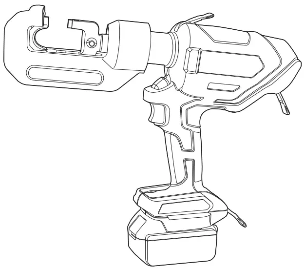
ABB TBM6PCR-LI Hydraulic Compression Tool
 Important
Read and understand all instructions and safety information in this manual before operating or servicing this tool. Be aware of proper usage and potential hazards.
![]() CAUTION:
CAUTION:
- Installations should be performed by a qualified electrician in accordance with national and local electrical codes.
 WARNING:
 - Risk of shock, disconnect power before installation.
- Never attempt to make a compression on a “HOT” Line.
- Never assume the power is OFF! Determine beforehand if any electrical hazards could exist when making a connection to line or wire.
- Tools are NOT insulated for use on or near conductors. Use of these tools near energized conductors may lead to electrical shock, causing severe injury or death. DO NOT use these tools near energized conductors.
 CAUTION:
 - Wear safety glasses and any other required PPE.
 WARNING:
 - Pinch points, keep hands and other body parts away from the crimping head when crimping. Compression dies at high force can cause severe personal injury. Failure to observe this warning could result in severe injury or death
General Information
![]() DANGER:
DANGER:
Safety rules:
- Keep work area clean and well lighted. Poor lighting and cluttered areas invite accidents.
- Maintain tool with care. Keep tool in good condition at all times. Keep it clean to help ensure best and safest performance.
- Don’t over-reach. Keep proper footing and balance at all times.
- Do not operate power tools in explosive atmospheres, such as in the presence of flammable liquids, gases or dust.
- Keep bystanders out of the work area while operating a power tool.
![]() CAUTION:
CAUTION:
Personal Safety:
- Do not use a tool while tired or under the influence of drugs, alcohol or medication.
- Use all required personal protection equipment
![]() WARNING:
WARNING:
Tool Use and Care
• Perform regular tool maintenance to help ensure trouble free service.
• Store tool in a cool dry area.
• After each use, wipe tool with clean cloth to remove any residue, especially close to the movable parts.
• Regularly lubricate moving parts.
• Clean plastic housing with a soft soaped cloth.
• Follow battery and charger use and care instructions.
• Do not force the tool.
• Discontinue use if on/off switch does not function properly. Contact tool services for repairs.
• Disconnect the battery pack from the tool before making any adjustments, changing accessories (including dies), or storing.
• When not in use, store tools out of the reach of children and unauthorized personnel.
• Regularly inspect tool for for misalignment or binding of moving parts, breakage of parts and any other condition that may affect the tool’s operation. Repair any damaged tool before use.
![]() CAUTION:
CAUTION:
Battery and Charger Use and Care
- Read all instructions and cautionary markings on battery charger, battery pack, and product using battery pack.
- To reduce the risk of injury, charge only MAKITA LXT 18V battery packs.*
- Do not expose charger and/or battery pack to precipitation, submerge in water.
- To reduce risk of damaging the electric plug and cord, Do not pull cord when disconnecting charger
- Protect cord from being stepped on, tripped over, or otherwise subjected to damage or stress.
- Do not disassemble charger or battery pack, contact Tool Service Center at 1-800-284-TOOL (8665) when service or repair is required.
- Do not store the tool and battery pack in damp or wet locations or where the temperature may reach or exceed 50°C (122°F) (such as a metal tool shed, or a car in the summer), which can lead to deterioration of battery’s ability to hold a charge.
- Do not pierce or open battery casing.
- Do not charge battery pack when the temperature is below 0°C (32°F) or above 40°C (104°F).
- The charger is designed to operate on standard 120V AC electrical power only. Do not use it on any other voltage.
- Charge the battery pack in a well-ventilated location.
- Only use battery and charger with accessories designed for ABB Model +TBM6PCR-LI.
- Do not use recycled or secondary market accessories or batteries.
- Do not short the battery pack or allow metal objects to touch the terminals.
- After removing the battery pack from the tool or the charger, always re-attach the pack cover.
- Replace damaged or deteriorated battery p
Features
- Fully automatic, self-contained power tool.
- Removable battery cartridge – simply change the cartridge for continuous use.
- One handed operation – control ram advancement and retraction with one hand.
- Protective rubber boot on “C” Head.
- Accepts Burndy “W” Dies.
Specifications
Hydraulic Compression Tool – TBM6PCR-LI:
- Drive Unit: 18V DC motor
- Dimensions: 10.6″L x 3.3″W x 13.7″H
- Weight: 8.3 lbs.
- Capacities: #8-600 kcmil CU or #8-400 Aluminum
- Jaw Opening: 1.8″
Battery (BAT-MK): - Battery type: MAKITA LXT Lithium Ion*
- Voltage: 18V DC
- Capacities: 5.0Ah
- Weight: 1.4 lbs.
- Charging time: 45 min. 100% Capacity
Charger (CHR-MK): - Input voltage: 120V 50-60 HZ AC Single Phase
- Weight: 1.7 lbs
Parts and Accessories
- Hydraulic Compression Tool (TBM6PCR-LI)
- Battery (BAT-MK)
- Charger (CHR-MK)
- Tool Hand Bag
Operating Instructions
Charging the battery
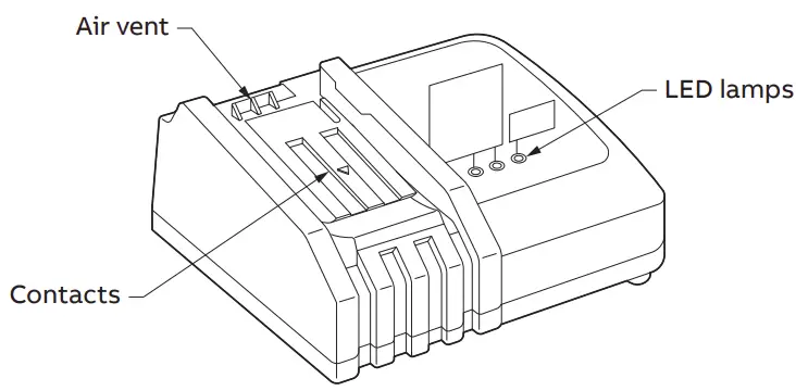
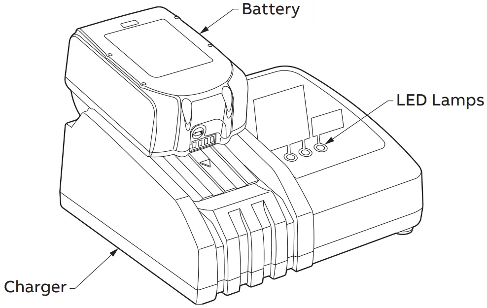
- Connect the battery charger BAT-MK to 120V AC. Charging light will repeatedly flash green.
- Insert the Battery firmly into the charger. The LED Lamp lights in red [CHARGING] and a brief preset melody will play. NOTE: If one or more lights flash red [HIGH TEMPERATURE], allow battery to remain in charger until cool before charging can initiate. NOTE: Do not place any foreign objects in the Charger.
- Full charge (100%) achieved in approximately 45 minutes. LED lamp lights green and melody or beep will indicate completion.
- When the battery will no longer charge or hold a charge, the LED Lamp blinks alternately from green to red [IMPOSSIBLE TO CHARGE].
- When the charger is out of order, the LED Lamp does not light up even if AC power is supplied. NOTE: Do not power the Charger with a portable generator or any other power source other than 120V AC.
Attaching & Detaching the battery pack
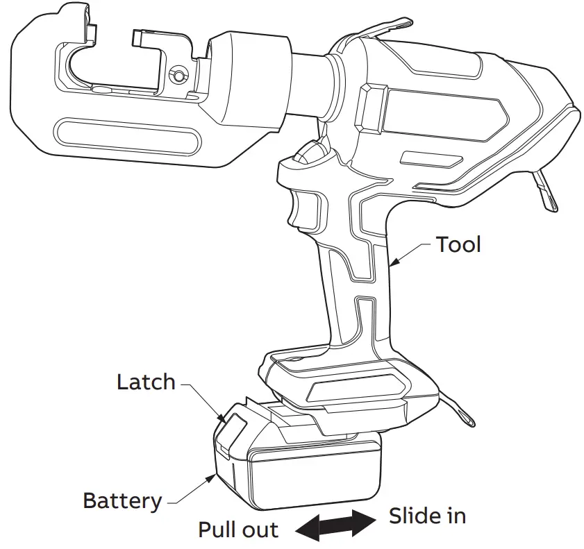
- Slide Battery into the base of the Tool until it stops and the latches engage.
- Gently pull Battery without pressing the latches.
- To detach, pull out the Battery while pressing the latches.
Compression cycles
This guide indicates the number of compression cycles that the TBM6PCR-LI can be expected to perform when the battery is fully charged. These figures are approximate and will vary according to the charging and other operating conditions, such as temperature, humidity, and battery condition
| Conductor | Average compressions per charge BAT-MK |
| 4/0 – 4/0 H-Tap | 600 |
| 500 kcmil | 550 |
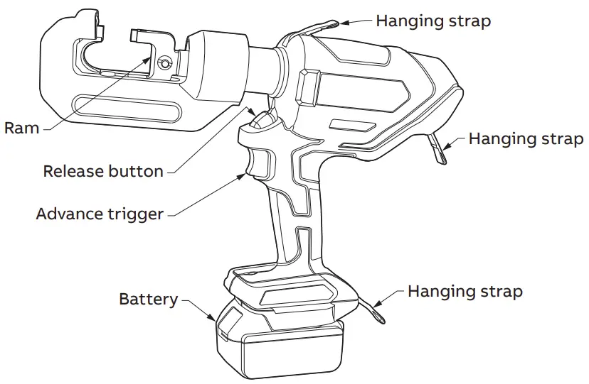
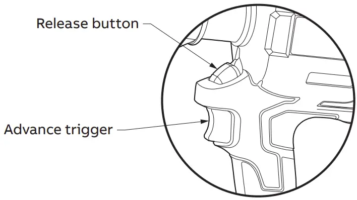
Switch operation
- The ram advances when the Trigger is depressed and stops when the Trigger is released.
- To retract the ram, depress the Release button. The ram continues to retract while the Release button is depressed. If the auto-retract feature is activated, the ram will automatically retract after the crimp is completed. See “Compression operation” section, page 4 for instructions on enabling and disabling the auto-retract function.
Compression operation
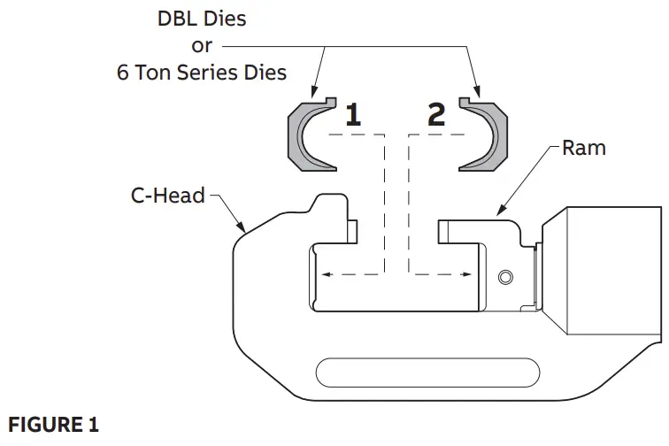
- Select the appropriate size dies for the connector being used.
- Insert one die half into the C-head. Insert the other half of the die into the Ram (Figure 1).
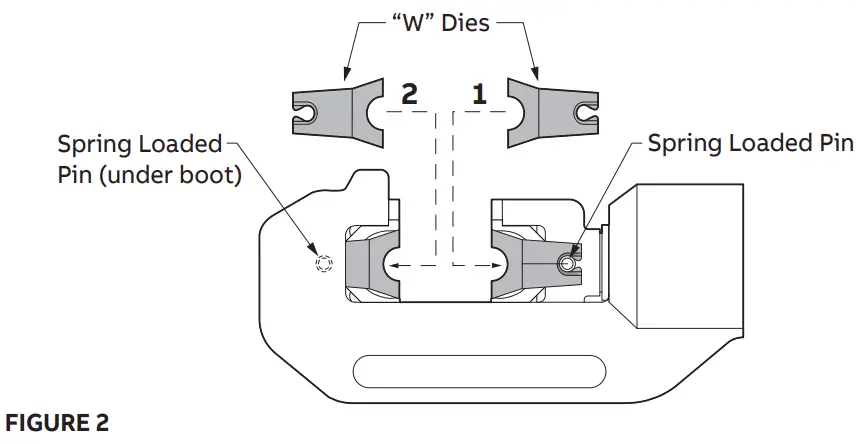
- The tool also accepts Burndy “W” type dies. Use of Burndy “W” dies requires that the die set DBL be installed first according to step 2. The “W” dies are then installed over the DBL dies and are secured in place by the spring loaded pins (Figure 2).
- Place connector between the dies. Press the trigger and advance the Ram (Switch operation, page 4) so the connector is held lightly between the dies. Do not deform the connector.
- Insert the conductor into the connector.
- Press the trigger until the compression is complete. A series of clicks will be heard followed by a release in the pressure when compression is complete. The LED indicator will display green followed by an audible beep when a complete compression is made. During an incomplete compression cycle, the LED indicator will flash red followed by a series of multiple audible beeps due to early release of the trigger or a low battery. The battery level can be checked by observing the gauge directly on the battery.
- Press the release button (Switch operation, page 4) to retract the ram. The ram continues to retract while the release button is pressed. The ram stops when it is fully retracted.
- Remove the compressed connector from the tool.
Auto retract
The auto retract feature can be toggled on or off depending on user preference or specific job requirement. To turn auto retraction off, remove rubber grommet and use a flat blade screwdriver to rotate the indicator 90 degrees to either position as shown below: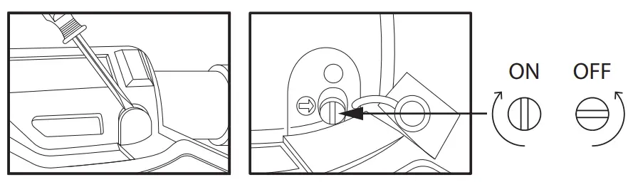
Troubleshooting guide
Before you begin
- Make sure that the battery is charged. Recheck the battery after several minutes to make sure the battery is holding its charge.
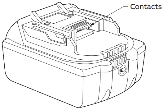
- Use a nonflammable contact cleaner or pencil eraser to clean the electrical contacts on the battery and tool.
- Reinstall the battery and check the tool again.
| Problem | Cause | Solution |
| Motor runs but the tool jaws will not advance | Insufficient hydraulic oil | Contact Tool Service Center for repair service |
| Air block in hydraulic system | Invert tool to allow air to rise towards the top of the oil bladder | |
| Defective hydraulic circuit | Contact Tool Service Center for repair service | |
| Motor runs, tool jaws advance, but will not build pressure | Insufficient hydraulic oil | Contact Tool Service Center for repair service |
| Defective suction valve or bypass cartridge | Contact Tool Service Center for repair service | |
| Motor will not run at all | Defective battery | Charge or replace battery |
| Bad contact or loose battery connections | Check all connections and wires | |
| Misaligned switch | Check to make sure that switch is properly aligned with trigger | |
| Contact Tool Service Center for repair service | ||
| Tool jaws will not release | Tool did not complete a full cycle and bypass | Press trigger and allow tool to bypass, then release tool jaws |
| Connector is jammed in tool jaws | Press and hold release trigger while prying tool jaws apart | |
| Release trigger is bent or misaligned | Contact Tool Service Center for repair service |
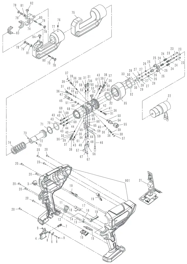
Parts list: TBM6PCR-LI
| No. | Description | Code | Qty |
| 901 | Housing L&R | MKHS-6REC | 1 |
| 3 | Cover | 758-02 | 1 |
| 4 | Switch Knob | 758-05 | 1 |
| 5 | Ratchet | 751-06 | 1 |
| 6 | Pin (280) | 751-08 | 1 |
| 7 | Spring (599) | R150-09 | 1 |
| 8 | Spring (720) | 751-09 | 1 |
| 9 | JE-3 Snap Ring | 51-39 | 2 |
| 10 | Terminal | 7ND-04 | 1 |
| 11 | Release Knob | 751-10 | 1 |
| 12 | Support Plate | 751-11 | 1 |
| 13 | Spring (719) | 751-12 | 1 |
| 14 | 3 x 22 Parallel Pin | ROB-121 | 1 |
| 15 | Indication Plate | 7ND-03 | 1 |
| 16 | M4x35 Parallel pin | 7ND-05 | 1 |
| 17 | On/Off switch pin | 751-13 | 1 |
| 18 | 3 x 10 Drive Pin (AW) | 32-12 | 1 |
| 19 | Hanging Strap | 558-07A | 3 |
| 20 | M4 x 10 Screw | ROB-159 | 9 |
| 21 | Switch Unit (24)S | 758-03 | 1 |
| 22 | Power Unit | MKREC-PCB | 1 |
| 23 | Pump Piston | 751-16 | 4 |
| 24 | Spring (699) | LI200-04 | 4 |
| 25 | Cylinder Insert | LI200-05 | 4 |
| 26 | P-5 Back-Up Ring (E.L.) | LI200-06 | 4 |
| 27 | P-5 O-ring (U565) | LI200-07 | 4 |
| 28 | M5 X 5 Screw (F.P.) | 510A-05 | 2 |
| 29 | Bush | R14A-19 | 1 |
| 30 | 5/32″ Ball | 22-21 | 8 |
| 31 | Plug | 751-17 | 4 |
| 32 | G35 O-Ring | 658-11 | 2 |
| 33 | Plug | SLND-12 | 1 |
| 35 | Oil Reservoir (43) | 658-01 | 1 |
| 36 | P-3 O-Ring (U801) | EZ-21 | 8 |
| 37 | SI-9 Ring | 751-19 | 4 |
| 38 | Filter | 751-20 | 4 |
| 39 | Suction Plug | 751-21 | 4 |
| 40 | Spring (688) | EZ-22 | 4 |
| 41 | Spring (718) | 751-22 | 1 |
| 42 | 7/32″ Ball | 16-26 | 1 |
| 43 | Valve Screw | EZ-27 | 6 |
| 44 | Spring (686) | EZ-26 | 4 |
| 45 | Valve Cartridge | 751-23B | 1 |
| 46 | Ground Wire | 758-06 | 1 |
| 47 | KK Stem | 751-24 | 1 |
| 48 | Stem (1) | 751-25 | 2 |
| 49 | Lever Retainer | 751-26 | 1 |
| 50 | P-5 O-Ring (B) | 610F-18 | 2 |
| 51 | S-7 O-Ring | 150A-05 | 1 |
| 52 | Screw | 751-27 | 1 |
| 53 | 9/64″ Ball | 751-30 | 2 |
| 54 | Pressure sensor | 758-07 | 1 |
| 55 | Set screw | 758-08 | 1 |
| 56 | Cam Lever | 751-28 | 1 |
| 57 | Release Lever | 758-04 | 1 |
| 58 | Spring (689) | EZ-23 | 1 |
| 59 | G4x12 Dowel Pin | 658-10 | 2 |
| 60 | Spring (77) | 16-37 | 1 |
| 61 | Spring (68) | 26-21 | 2 |
| 62 | P-2 Back-Up Ring (B.C.) | RCP-37 | 1 |
| 63 | P-2 O-Ring | RCP-38 | 1 |
| 64 | P-3 O-Ring | 16-36 | 2 |
| 65 | M3 X 5 Screw (F.P.) | UC-37A | 2 |
| 66 | Retainer | SLND-14 | 2 |
| 67 | M3x10 Screw | 658-08 | 2 |
| 68 | Body | 751-34 | 1 |
| 69 | 3/16″ Ball | 16-49 | 4 |
| 70 | P-29 O-Ring | 16-23 | 1 |
| 71 | P-29 Back-Up Ring (B.C.) | 16-22 | 1 |
| 72 | Ram | CN7-01 | 1 |
| 73 | M4 X 5 Screw (C.P.) | 55A-24 | 2 |
| 74 | Ram Spring (446) | 20-76 | 1 |
| 75 | Head Insulation (1) | RC58-03 | 1 |
| 76 | M5 X 8 Screw (C.P.) | P55A-02 | 1 |
| 77 | Head | RC58-02 | 1 |
| 78 | Retaining Screw | 58-01 | 4 |
| 79 | Push Pin | 58-02 | 4 |
| 80 | Spring (5) | 58-03 | 2 |
| 81 | Collar | 58-04 | 2 |
| 82 | Die Retaining Screw | C58-02 | 1 |
| 83 | D3 Saddle Die | C58-03 | 2 |
Exploded assembly
We reserve the right to make technical changes or modify the contents of this document without prior notice. With regard to purchase orders, the agreed particulars shall prevail. ABB does not accept any responsibility whatsoever for potential errors or possible lack of information in this document.
We reserve all rights in this document and in the subject matter and illustrations contained therein. Any reproduction – in whole or in part
- is forbidden without prior written consent of ABB. © 2021 ABB Installation Products Inc. and/or its related companies. All Rights Reserved.
tnb.abb.com (US/Latin America)
tnb.ca.abb.com (Canada)abb.com
Warranty: www-public.tnb.com/warranty/
ta04790-tb2.pdf
Registration: tnb.abb.com/toolregistration