![]()
DeatschWerks
Universal DW200/300 Fuel Pump Installation Guide
9-201/301-1000
Universal 1980-2000 DW200/300 Fuel
Pump Installation Guide
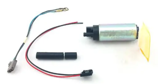
Parts List:
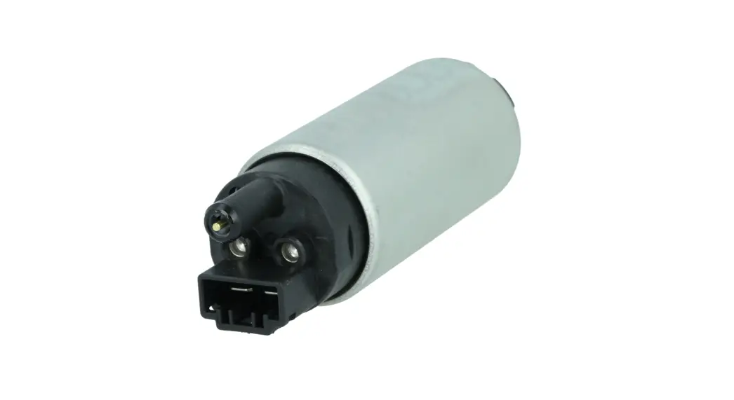
- DW200/300
- Fuel Sock w/ Retainer Clip
- 3” Submersible Fuel Injection Hose
- 5/16” Hose Clamps (x2)
- Electrical Connector w/ Leads
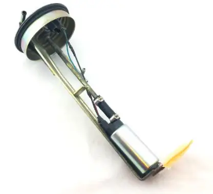
Universal Metal Hanger DW200/300 Fuel Pump Install
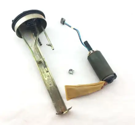
PLEASE READ – this guide is intended to aid in the installation of our products. It is recommended that factory manuals or instructions are followed to remove the fuel pump assembly from the vehicle. Instructions in this guide are generic and are intended to aid in the installation of a DW200/300 pump in the typical 1980-2000 metal fuel pump hanger. The factory manual should supersede any contradiction. Below is a picture of suggested tools that will make the installation process easier.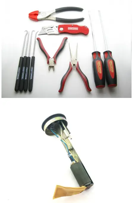
- – separate the pump from the assembly, use caution when removing connectors and clips and inspect the wiring and soft components condition for consideration of reuse.

- – prep the DW pump with components from the universal installation kit and reusable OE components.

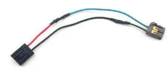
- – if applicable, splice the OE connector with the electrical connector from the installation kit.
NOTE: in this example, the connector was soldered together and covered with fuel resistant tape. Covered (fuel safe) connectors can also be used.
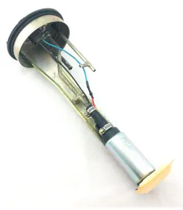
- – install the DW pump and plug in the connector


- – reinstall the assembly into the fuel tank and attach a length of hose to the outlet of the pump assembly allowing it to drain into a fuel safe container and prime the fuel pump assembly
- – cycle the key to the on position as many times as required to prime the pump assembly and evacuate the air introduced during the pump installation process
- – attach supply line to the outlet of the pump assembly