
Carrier 30RBY Air-Cooled Ducted Liquid Chillers
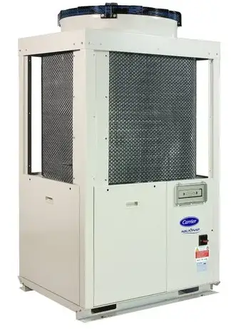
Nominal cooling capacity 30RBY: 16-32 kW
The Aquasnap liquid chiller/heat pump range was designed for commercial applications such as the air conditioning of offices and hotels etc. The new Aquasnap units integrate the latest technological innovations:
- Ozone-friendly refrigerant R410A
- Scroll compressors
- Low-noise fans
- Auto-adaptive microprocessor control
The Aquasnap units are equipped with a hydraulic module integrated into the unit chassis, limiting the installation to straightforward operations like connection of the power supply and the water supply and return piping.
FEATURES
Quiet operation
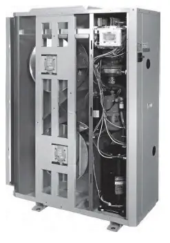
- Compressors
- Low-noise scroll compressors with low vibration levels
- The compressor assembly is supported by anti-vibration mountings
- Air heat exchanger section
- Vertical air heat exchanger coils
- The latest-generation low-noise fans are now even quieter and do not generate intrusive low-frequency noise
Access panels, 30RBY 017-021
Easy and fast installation
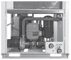
- Integrated hydraulic module
- Fixed speed circulator
- Water filter protecting the water pump against circulating debris
- High-capacity membrane expansion tank ensures pressurisation of the water circuit
- Overpressure valve, set to 4 bar Automatic purge valve positioned at the highest point of the hydraulic module to remove air from the system.
- Thermal insulation and frost protection down to -10°C, using an electric resistance heater and pump cycling. Integrated water fill system to ensure correct water pressure (option)
- Physical features
- With its small footprint the unit blends in with any architectural styles.
- The unit is enclosed by easily removable panels, covering all components (except air heat exchanger and fans).
- Simplified electrical connections
- A single power supply point (power supply without neutral available as an option and in standard for units size 40kW)
- Main disconnect switch with high trip capacity Transformer for safe 24 V control circuit supply included
- Fast commissioning
- Systematic factory operation test before shipment
- Quick-test function for step-by-step verification of the instruments, electrical components and motors.
- Easy duct connection (30RBY version only)
- Rectangular discharge air connection.
- Fan with 80 Pa available pressure. Centrifugal fan for sizes 017 and 021, and axial fan for sizes 026 and 033.
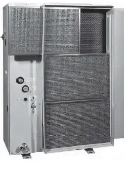
- Rectangular suction and filter connection option (sizes 017 and 021 only).
Inlet filters, RBY 017-021
FEATURES
Economical operation
- Increased energy efficiency at part load
- Specific Free Defrost algorithm is present to optimise performance and comfort even during defrost period.
- Reduced maintenance costs
- Maintenance-free scroll compressors
- Fast diagnosis of possible incidents and their history via the Pro-Dialog+ control
- R410A refrigerant is easier to use than other refrigerant blends
Environmental care
- Ozone-friendly R410A refrigerant
- Chlorine-free refrigerant of the HFC group with zero ozone depletion potential
- Very efficient – gives an increased energy efficiency ratio (EER)
- Leak-tight refrigerant circuit
- Brazed refrigerant connections for increased leak tightness
- Verification of pressure transducers and temperature sensors without transferring refrigerant charge
Hydraulic module, sizes 026-040
Superior reliability
- State-of-the-art concept
- Cooperation with specialist laboratories and use of limit simulation tools (finite element calculations) for the design of the critical components, e.g. motor supports suction/discharge piping etc.
- Auto-adaptive control
- Control algorithm prevents excessive compressor cycling and permits reduction of the water quantity in the hydraulic circuit (Carrier patent)
- Exceptional endurance tests
- Corrosion resistance tests in salt mist in the laboratory
- Accelerated ageing test on components that are submitted to continuous operation: compressor piping, fan supports
- Transport simulation test in the laboratory on a vibrating table.
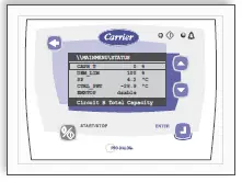
Pro-Dialog+ control
Pro-Dialog+ combines intelligence with operating simplicity. The control constantly monitors all machine parameters and precisely manages the operation of compressors, expansion devices, fans and of the water heat exchanger water pump for optimum energy efficiency.
Pro-Dialog+ interface
- Energy management
- Seven-day internal time schedule clock: Permits unit on/ off control and operation at a second set point
- Set point reset based on the outside air temperature or the return water temperature or on the water heat exchanger delta
- Master/slave control of two units operating in parallel with operating time equalisation and automatic change- over in case of a unit fault.
- Change-over based on the outside air temperature
- Integrated features
Night mode: Capacity and fan speed limitation for reduced noise level - Ease-of-use
- The new backlighted LCD interface includes a manual control potentiometer to ensure legibility under any lighting conditions.
- The information is displayed clearly in English, French German, Italian and Spanish (for other languages please consult Carrier)
- The Pro-Dialog+ navigation uses intuitive tree-structure menus, similar to the Internet navigators. They are user friendly and permit quick access to the principal operating parameters: number of compressors operating, suction/ discharge pressure, compressor operating hours, set point, air temperature, entering/leaving water temperature.
Remote operating mode with volt-free contacts (standard)
A simple two-wire communication bus between the RS485 port of the Aquasnap and the Carrier Comfort Network offers multiple remote control, monitoring and diagnostic possibilities. Carrier offers a vast choice of control products, specially designed to control, manage and supervise the operation of an air conditioning system. Please consult your Carrier representative for more information on these products,
- Start/stop: Opening of this contact will shut down the unit
- Dual set point: Closing of this contact activates a second set point (example: Unoccupied mode)
- Alert indication: This volt-free contact indicates the presence of a minor fault
- Alarm indication: This volt-free contact indicates the presence of a major fault that has led to the shut-down of the unit
- User safety: This contact can be used for any customer safety loop, closing of the contact generates a specific alarm
- Out of service: This signal indicates that the unit is completely out of service
- Unit capacity: This analogue output (0-10 V) gives an immediate indication of the unit capacity
- Compressor operation: This contact signals that the compressor is in operation
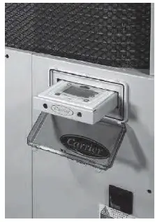
Remote interface (option)
This interface allows access to the same menus as the unit interface and can be installed up to 300m away. It includes a box that can be mounted inside the building. The power supply is provided via a 220 V/24V transformer supplied.
Interface access, sizes 026-040
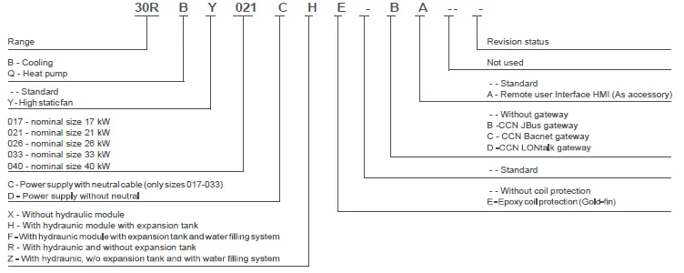
TYPE KEY
PHYSICAL DATA, 30RBY UNITS
| 30RBY | 017 | 021 | 026 | 033 | |||
| Cooling | |||||||
| Standard unit Full load performances* | CA1 | Nominal capacity | kW | 15,7 | 20,3 | 27,0 | 32,3 |
| EER | kW/kW | 2,65 | 2,60 | 2,88 | 3,05 | ||
| Eurovent class | B | B | A | A | |||
| CA2 | Nominal capacity | kW | 19,9 | 24,8 | 36,1 | 42,3 | |
| EER | kW/kW | 3,07 | 2,85 | 3,49 | 3,67 | ||
| Eurovent class | E | E | B | ||||
| Standard unit | SEPR -2/-8°C Process medium temp.*** kWh/kWh | 2,61 | 2,64 | 2,62 | 2,61 | ||
| SEPR 12/7°C | kWh/kWh | 4,17 | 4,03 | 4,29 | 4,06 | ||
| SEER 12/7°C | kWh/kWh | 2,76 | 2,72 | 2,86 | 3,08 | ||
| SEER 23/18°C | kWh/kWh | 3,10 | 3,05 | 3,28 | 3,52 | ||
| Integrated Part Load Value | kW/kW | 3,340 | 3,300 | 3,490 | 3,690 | ||
| Operating weight(1) | |||||||
| Standard unit, with hydraulic module | kg | 209 | 228 | 255 | 280 | ||
| Standard unit, without hydraulic module | kg | 193 | 213 | 237 | 262 | ||
| Sound pressure level(2) | dB(A) | 50 | 50 | 53 | 53 | ||
| Sound power level radiated from the unit(3) | dB(A) | 82 | 82 | 85 | 85 | ||
| Sound power level at unit discharge(3) | dB(A) | 80 | 80 | 91 | 91 | ||
| Dimensions | |||||||
| Length | mm | 1135 | 1135 | 1002 | 1002 | ||
| mm | 584 | 584 | 824 | 824 | |||
| Height | mm | 1608 | 1608 | 1829 | 1829 | ||
| Compressor | One hermetic scroll compressor | ||||||
| Refrigerant charge R-410A | kg | 5,5 | 6,4 | 5,8 | 8,6 | ||
| teqCO2 | 11,5 | 13,4 | 12,1 | 18,0 | |||
| Control | |||||||
| Fans | Two 2-speed centrifugal fans, 5 backward-curved | One 2-speed axial fan, 7 blades | |||||
| mm | 454 | 454 | 630 | 630 | |||
| Number of blades | 5 | 5 | 7 | 7 | |||
| Available static pressure | Pa | 80 | 80 | 80 | 80 | ||
| l/s | 1640 | 1640 | 3472 | 3472 | |||
| Speed | r/s | 20,5 | 20,5 | 21,5 | 21,5 | ||
| Water heat exchanger | One plate heat exchanger | ||||||
| Water volume | l | 1,52 | 1,90 | 2,28 | 2,85 | ||
| Maximum operating pressure | kPa | 1000 | 1000 | 1000 | 1000 | ||
PHYSICAL DATA, 30RBY UNITS
| 30RBY | 017 | 021 | 026 | 033 | |
| Air heat exchanger | |||||
| Pipe diameter | in | 3/8 | 3/8 | 3/8 | 3/8 |
| Number of rows | 2 | 2 | 2 | 3 | |
| Number of pipes per row | 60 | 60 | 60 | 60 | |
| Fin spacing | mm | 1,69 | 1,69 | 1,69 | 1,69 |
| Standard unit | |||||
| Water connections (MPT gas) | in | 1 | 1 | 1-1/4 | 1-1/4 |
| Unit with hydraulic module |
pressure gauge, automatic air purge valve, relief valve, water circuit drain valve | ||||
| Pump | One single-speed pump, maximum water-side operating pressure 400 kPa | ||||
| Expansion tank capacity | l | 5 | 5 | 8 | 8 |
| Entering water connection | in | 1-1/4 | 1-1/4 | 1-1/4 | 1-1/4 |
| Leaving water connection | in | 1 | 1 | 1-1/4 | 1-1/4 |
| Chassis paint colour | Colour code: RAL 7035 | ||||
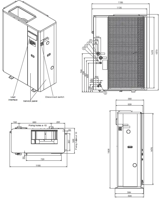
DIMENSIONS/CLEARANCES
30RBY 017-021 – standard units
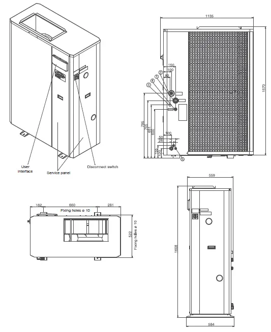
Legend
All dimensions are in mm
- Water inlet
- Water outlet
- Water fill kit connection (option)
- Relief valve
- Power connections
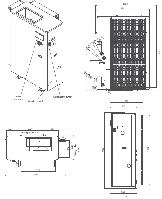
30RBY 017-021 – units with return air ducts
Legend
All dimensions are in mm
- Water inlet
- Water outlet
- Water fill kit connection (option)
- Relief valve
- Power connections
30RBY 017-021 – units with filter frame on the return air side
Legend
All dimensions are in mn
- Water inlet
- Water outlet
- Water fill kit connection (option)
- Relief valve
- Power connections
30RBY 026-033
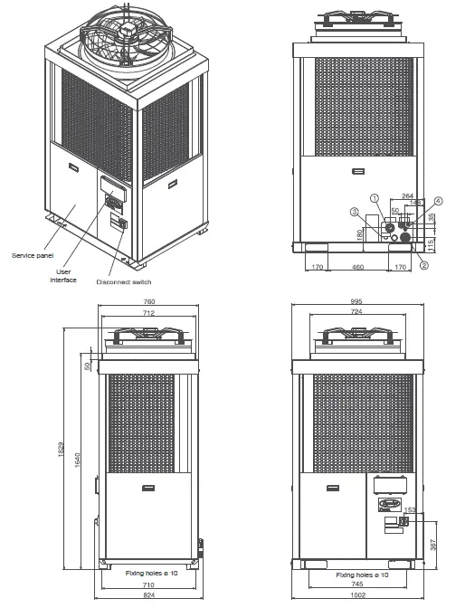
Legend
All dimensions are in mn
- Water inlet
- Water outlet
- Water fill kit connection (option)
- Relief valve
- Power connections


 User Manual")


