![]() CT6Y Ebike Display Cash Counter
CT6Y Ebike Display Cash Counter
Owner’s Manual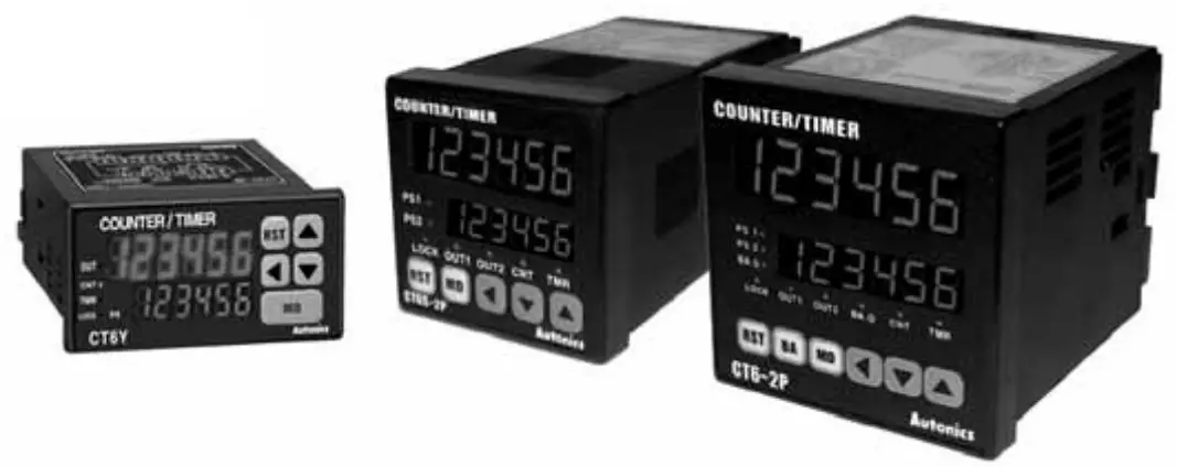
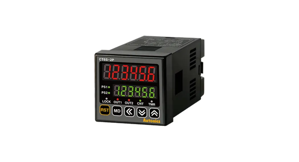
CT6Y Ebike Display Cash Counter
DIN W 72 x H 36 mm, W 48 x H 48 mm, W 72 x H 72 mm Counter/Timer
Touch Type Counter/Timer
(A) Counter
(B) Timer
(C) Temp. controller
(D) Power controller
(E) Panel meter
(F) Tacho/Speed/Pulse meter
(G) Display unit
(H) Sensor controller
(I) Switching power supply
(J) Proximity sensor
(K) Photo electric sensor
(L) Pressure sensor
(M) Rotary encoder
(N) Stepping motor & Driver & Controller
(O) Graphic panel
(P) Field network device
(Q) Production stoppage models & replacement
Features
- Selectable Counter or Timer function
- Multi—functional Counter/Timer (Includes 829,728 functions)
- Prescale function
- High speed counting of 10keps
- Batch counter function for CT6, CT6—2P only
- Selectable Voltage input (PNP) or No voltage input (NPN)
- Able to set ON/OFF time individually in Flicker (FLK) mode
- Key Lock function
![]() Please read “Caution for your safety” in operation manual before using.
Please read “Caution for your safety” in operation manual before using.
![]()
Ordering information
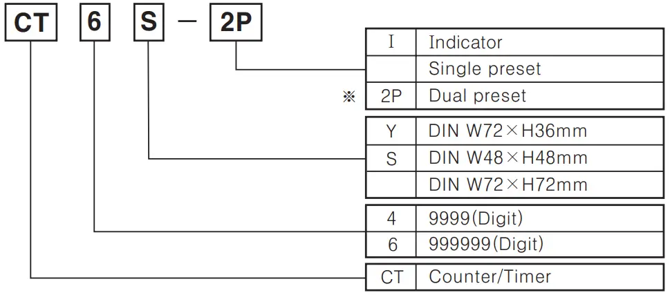
![]() When using dual preset as a timer, setting time is limited to one time
When using dual preset as a timer, setting time is limited to one time
Specifications
| Model | Single preset | CT6Y | CT4S | CT6S | CT6 | ||
| Dual preset | CT6Y-2P | CT4S-2P | CT6S-2P | CT6-2P | |||
| Indicator | CT6Y-1 | — | CT6S-I | CT6-I | |||
| Digit | 6 | 4 | 6 | (3 | |||
| Digit size | PV: W4.5 x Hl0 mm SV: W3.5 x H7mm | PV: W7 x H1 lmm SV: W 5 x H8 mm | PV: W 4.5 x H10 mm SV: W 3.5x H7 mm | PV: W 7 x H 13mm SV: W 5 x H 9mm | |||
| Power supply | AC | 100-240VAC 50/60Hz | |||||
| AC/DC | 24VAC 50/60Hz/24-60VDC (Option) | ||||||
| Allowable voltage range | 90 ∼ 110% of rated voltage(AC power) | ||||||
| Power consumption | AC | CT6Y-I: Approx. 5VA, CT6Y: Approx. 6.5VA, CT6Y-2P: Approx. 7VA (240VAC 50/60Hz) | CT4S: Approx. 4.6VA, CT4S-2P: Approx. 5.5 VA (240VAC 50/60Hz) | CT6S-I: Approx. 4.3 VA, CT6S: Approx. 5.2 VA, CT6S-2P: Approx. 6VA (240VAC 50/60Hz) | CT6-I: Approx. 9VA, CT6: Approx. 10VA, CT6-2P: Approx. 10VA (240VAC 50/60Hz) | ||
| AC/DC | CT6Y-I: Approx. 3W, CT6Y: Approx. 4W, CT6Y-2P: Approx. 4W(24VDC) CT6Y-I: Approx. 6VA, CT6Y: Approx. 7VA, CT6Y-2P: Approx. 7VA (24VAC 50/60Hz) | CT4S: Approx. 3W, CT4S-2P: Approx. 3.5W (24VDC) CT4S: Approx. 6VA, CT4S-2P: Approx. 7VA (24VAC 50/60Hz) | CT6S-I: Approx. 2.7W, CT6S: Approx. 3.4W, CT6S-2P: Accrox 4W(24 VIDC) CT6S-I: Approx. 5.4 VA, CT6S: Approx. 6.8VA, CT6S-2P: Approx. 7VA (24VAC 50/60Hz) | CT6-I: Approx. 5W, CT6: Approx. 5W, CT6-2P: Approx. 6W(24 VDC) CT6-I: Approx. 9VA, CT6: Approx. 10VA, CT6-2P: Approx. 10VA (24VAC 50/60Hz) | |||
| Counting speed of INA. INB | Selectable 1 / 30 / 1k / 5k / 10kcps | ||||||
| Min. input signal width | Counter | Reset input : Selectable lms or 20ms | |||||
| Timer | INA, INHIBIT, RESET : Selectable lms or 20ms | INA, RESET, INHIBIT, BATCH RESET(Except CT6-0 Selectable lms or 20ms | |||||
| Input | Selectable voltage input or No-voltage input [Voltage input] Input impedance: 5.41a2, “H” level : 5-30VDC, “L” level : 0-2VDC [No-voltage input] Short-circuit impedance : Max. 1k52, Residual voltage : Max. 2VDC, Open-circuit impedance : Min. 1001a2 | ||||||
| One-shot output | 10 / 50 / 100 / 200 / 500 / 1000 / 2000 / 5000ms | ||||||
| Control output | Contact | Type | Single preset type: SPDT(1c) Dual preset type SPST(1a) for first output SPDT(1c) for second output | Single preset type : SPDT(1c), Dual preset type : SPST (1a) for first/second output | Single preset type: SPDT (1c) Dual preset type SPST(la) for first output SPDT(1c) for second output | ||
| Capacity | NO contact: 250VAC 3A resistive load, NC contact : 250VAC 2A at resistive load | ||||||
| Control output | Solid- state | Type | Single preset type: 1 NPN open collector Dual preset type : 1 NPN open collector | Single preset type: 2 NPN open collectors Dual preset type: 3 NPN open collectors | |||
| Capacity | Max. 30VDC, Max. 100mA | ||||||
| Memory protection | 10 years(When using non—volatile semiconductor memory) | ||||||
| External power | 12VDC ± 10%, Max. 100mA | ||||||
| Timer accuracy | Repeat error | Power ON start : Max. ±0.01% ±-0.05 sec Signal start : Max. ±0.01% ±-0.03sec | |||||
| Set error | |||||||
| Voltage error | |||||||
| Temperature error | |||||||
| Insulation resistance | Min. 100MQ (at 500 VDC megger) | ||||||
| Dielectric strength | 2000 VAC 50/60Hz for 1 minute | ||||||
| Noise strength | ±2kV the square wave noise (pulse width:lμs) by the noise simulator | ||||||
| Vibration | Mechanical | 0.75mm amplitude at frequency of 10 — 55Hz in each of X, Y, Z directions for 1 hour | |||||
| Malfunction | 0.5mm amplitude at frequency of 10 — 55Hz in each of X, Y, Z directions for 10 minutes | ||||||
| Shock | Mechanical | 300m/s² (Approx. 30G) in X,Y,Z directions for 3 times | |||||
| Malfunction | 100m/s² (Approx. 10G) in X,Y,Z directions for 3 times | ||||||
| Relay life cycle | Mechanical | Min. 10,000,000 times | |||||
| Electrical | Min. 100,000 times(NO : 250VAC 3A at resistive load, NC : 250VAC 2A at resistive load) | ||||||
| Protection | IP65 (Front panel only) | ||||||
| Ambient temperature | —10 ∼ +55°C (at non—freezing status) | ||||||
| Storage temperature | —25 ∼ +65°C (at non—freezing status) | ||||||
| Ambient humidity | 35 — 85%RH | ||||||
| Unit weight | AC power | CT6Y: Approx. 160g CT6Y-2P: Approx. 163g CT6Y—I: Approx. 127g | CT4S: Approx. 155g, CT4S-2P: Approx. 162g | CT6S: Approx. 155g CT6S-2P: Approx. 162g CT6S—I: Approx. 136g | CT6: Approx. 264g CT6-2P: Approx. 271g CT6—I: Approx. 244g | ||
| AD/DC power | CT6Y: Approx. 164g CT6Y-2P: Approx. 167g CT6Y—I: Approx. 130g | CT4S: Approx. 152g CT4S-2P: Approx. 159g | CT6S: Approx. 152g CT6S-2P: Approx. 159g CT6S—I: Approx. 133g CT6-2P: Approx. 270g | CT6: Approx. 263g CT6—L: Approx. 243g | |||
| Approval | |||||||
Connections
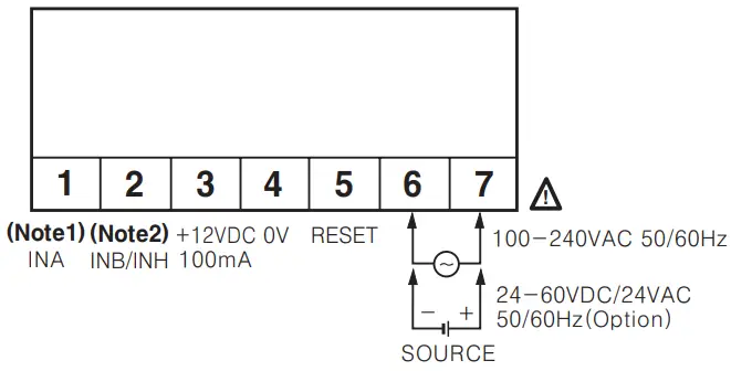
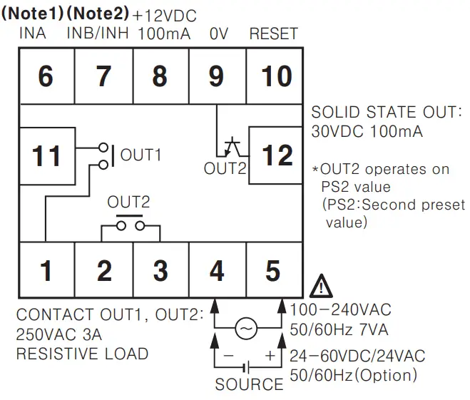
- CT6Y

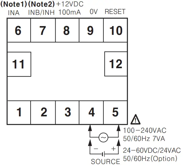
- CT6Y-1

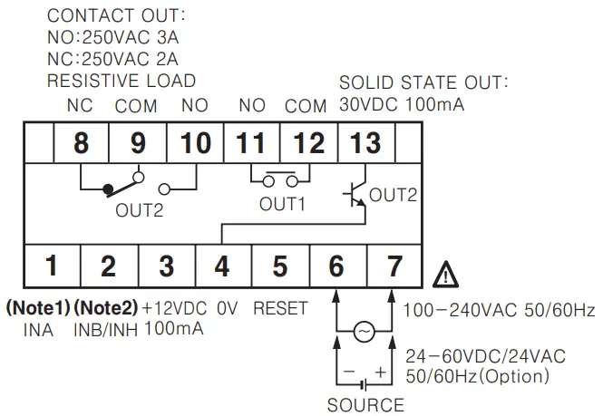
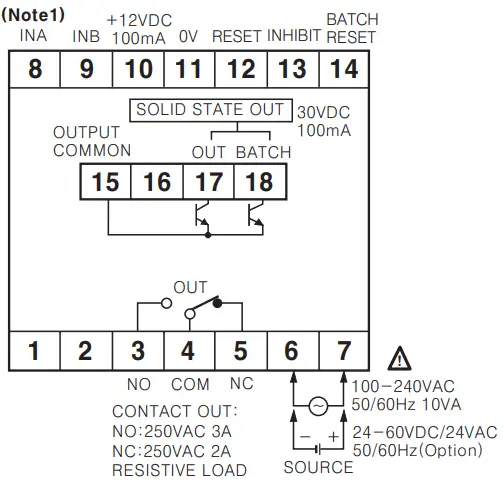
- CT6Y-2P

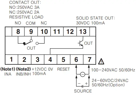
 (Note 1) INA terminal
• Counter mode Used for “count” or “inhibition” signal input
• Timer mode: Used for “START” signal input(Note 2) INB/INH terminal
• Counter mode: Used for INB signal input terminal
• Timer mode: Used for INH signal input terminal
If the signal is applied to INH terminal, the processing time is stopped. (Time hold) Connection of relay contact input when voltage input (PNP) is selected Connection of relay contact input when No-voltage input(NPN) is selected
- CT4S, CT6S
 (Note 1) INA terminal
• Counter mode: Used for “count” or “inhibition” signal input
• Timer mode: Used for “START” signal input(Note 2) INB/INH terminal
• Counter mode: Used for INB signal input terminal
• Timer mode: Used for INH signal input terminal
If the signal is applied to INH terminal, the processing time is stopped. (Time hold) - CT 6

- CT6-1

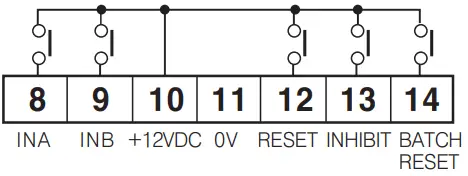
- CT4S-2P, CT6S-2P

- CT6S-1
 • Connection of relay contact input when voltage input (PNP) is selected
 • Connection of relay contact input when No—voltage input (NPN) is selected
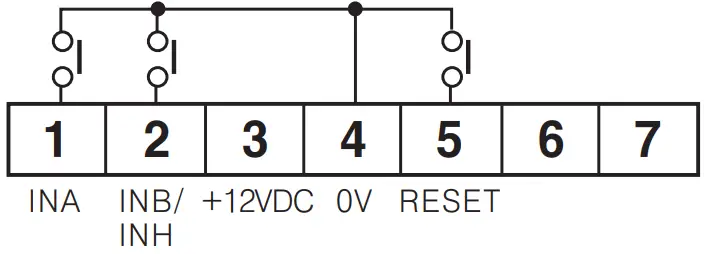
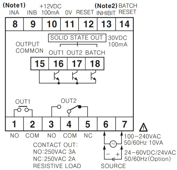
- CT6-2P
 (Note 1) INA terminal
• Counter mode: Used for “count” or ‘inhibition” signal input
• Timer mode: Used for “START” signal input (Note 2) INHIBIT signal
• If the signal is applied to INH terminal, the processing time is stopped (Time hold) Solid state output is insulated from inner circuit by photo coupler.
(Power supply: 5-30VDC Max.)
• Connection of relay contact input when voltage input (PNP) is selected • Connection of relay contact input when No—voltage input(NPN) is selected
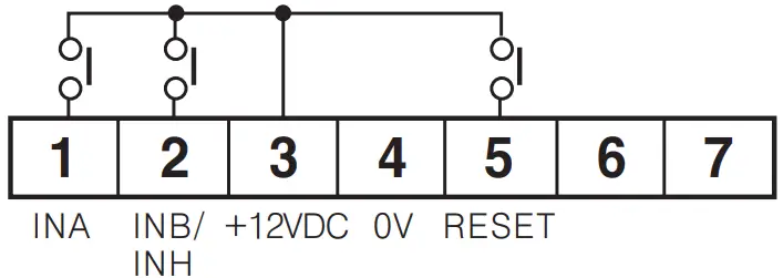


 • Connection of relay contact input when voltage input (PNP) is selected
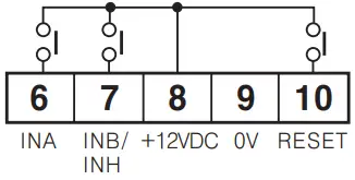 • Connection of relay contact input when No—voltage input (NPN) is selected
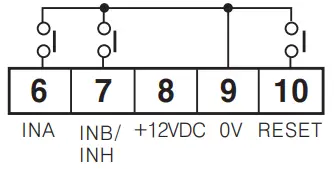
 • Connection of relay contact input when No—voltage input(NPN) is selected
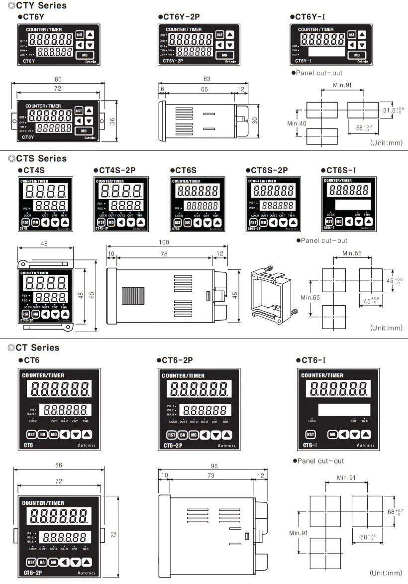
Dimensions
Front panel identification
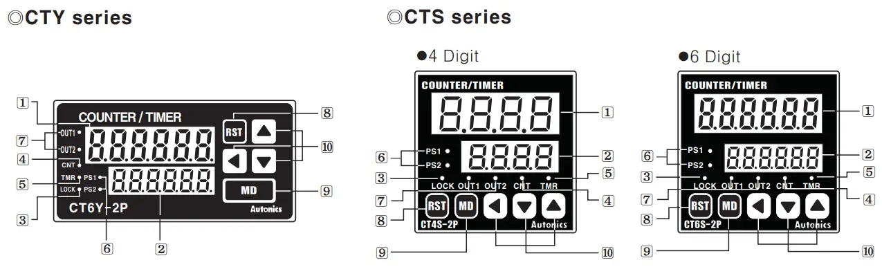
- Display for process value(Red LED)
Count value(Counter)/Process time(Timer)/Setting symbols LED height: 11mm for 4 digit, 10mm for 6 digit - Display for setting value(Yellow—Green LED)
Setting value(Counter)/Preset time(Timer) and setting symbols LED height: 8mm for 4 digit, 7mm for 6 digit - LOCK: Key Lock indication
– Lock OFF: Light OFF
– Lock ON: Light ON - CNT: Indicates operation as a counter
- TMR: Indicates operation as a timer
– LED flashes when timer operates
– LED turns on when the time stop operating - PST, PS2 : Indicates that preset is being displayed or changed
- OUT1, OUT2 : Indicating the operation of output
 : Reset key
 : Mode key
 : Set key
![]() There is no (6), (7) LED in CT6Y-I, CT6S-1
There is no (6), (7) LED in CT6Y-I, CT6S-1![]() In CT4S, CT6S. CT6Y, PS2 will be changed to PS and OUT 2 is OUT and there is no PS1, OUT1 LED.
In CT4S, CT6S. CT6Y, PS2 will be changed to PS and OUT 2 is OUT and there is no PS1, OUT1 LED.
![]() In CT6, PS2 will be changed to PS and OUT2 to OUT, since there is no PS1, OUT1 LED.
In CT6, PS2 will be changed to PS and OUT2 to OUT, since there is no PS1, OUT1 LED.![]() There are no PS1, PS2, BA.S, OUT1, OUT2, BA.O LED in CT6—I.
There are no PS1, PS2, BA.S, OUT1, OUT2, BA.O LED in CT6—I.![]() There is no e key in CT6—I.
There is no e key in CT6—I.
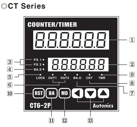
- Display for process value(Red LED)
Count value(Counter)/Process time(Timer)/Setting symbols LED height: 13mm - Display for setting value(Yellow—Green LED)
Setting value(Counter)/Setting time(Timer) and setting symbols LED height: 9mm - PS1, PS2: Indicates which setting value(Single, Dual) is being displayed or changed
- BA.S: Set a batch setting value and display the change
—Use BA.S: Turn ON
—Not use BA.S: Turn OFF - LOCK: Display Key Lock operation
—Use Lock: Turn ON
—Not use Lock: Turn OFF - OUT1, OUT2 : Preset the operation of output(Single & Dual)
- BA.O : Indicates operation as BATCH output
- CNT : Indicates operation as counter
- TMR : Indicates operation as timer
—LED flashes when the timer is operating
—LED turns on when the timer stops operating - : Reset key
- : Batch key
- : Mode key : Set key
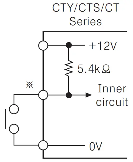
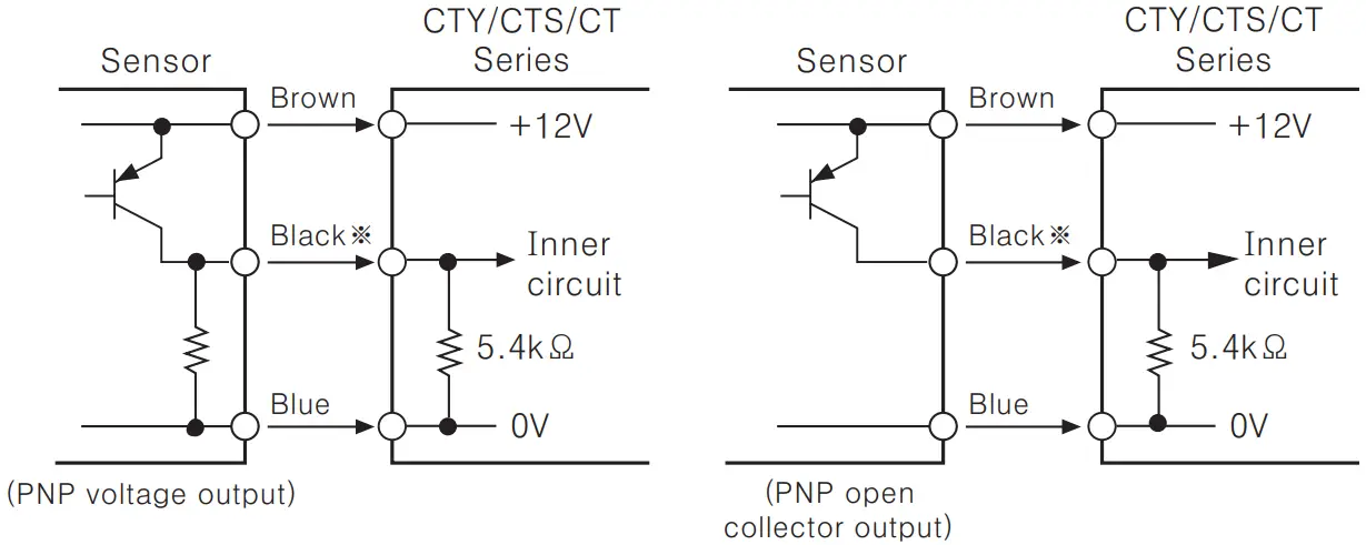
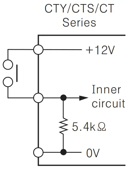
Input connections
![]() No-voltage input(NPN)
No-voltage input(NPN)
- Solid—state input(Standard sensor: NPN output type sensor)
 INPUT circuit of INA, INB, INH(INHIBIT), BATCH RESET, RESET are the same. INA is input terminal when it is used for Counter and can be START signal input terminal when it is used for Timer.
 - Contact input
 Please select the counting speed as 1 cps or 30 cps when it is used for counter.
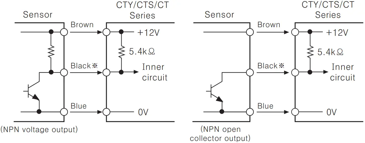
![]() Voltage input(PNP)
Voltage input(PNP)
- Solid—state input(Standard sensor: PNP output type sensor)
 INPUT circuit of INA, INB, INH(INHIBIT), BATCH RESET, RESET are the same. INA is input terminal when it is used for Counter and can be START signal input terminal when it is used for Timer.
 - Contact input

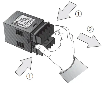
Input logic selection
![]() CTY/CTS Series
CTY/CTS Series
- The power must be cut off.
- Detach the case from the body.
 * Case detachment
Squeeze toward ① and pull toward ② as shown in picture Please check if the power is cut off.
 - Select input logic by using input logic switch inside Counter/Timer.

- Please assemble opposite way of the case detachment.
- Then apply the power to Counter/Timer.
 * Case detachment
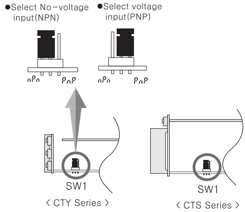
![]() CT Series
CT Series
It is easy to change input logic by switch.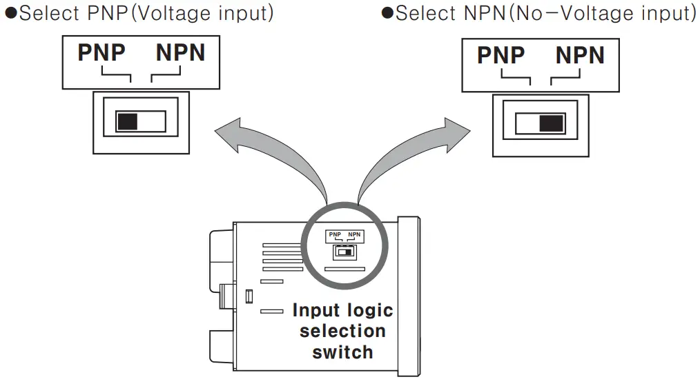
Output connections
![]() Contact output
Contact output
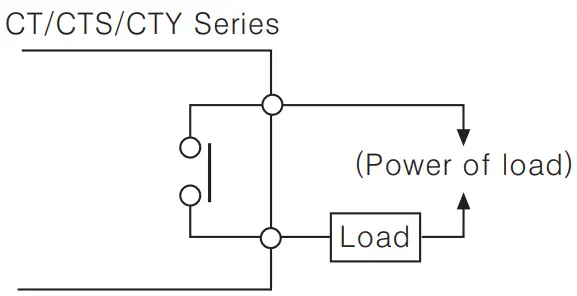
![]() Contact capacity is max 50 VAC 3A. Use proper load not to exceed the capacity.
Contact capacity is max 50 VAC 3A. Use proper load not to exceed the capacity.![]() When use inductive load (Relay, etc), surge absorber (Diode, Varistor etc) should be connected at both—edge of load.
When use inductive load (Relay, etc), surge absorber (Diode, Varistor etc) should be connected at both—edge of load.
![]() Solid—state output
Solid—state output
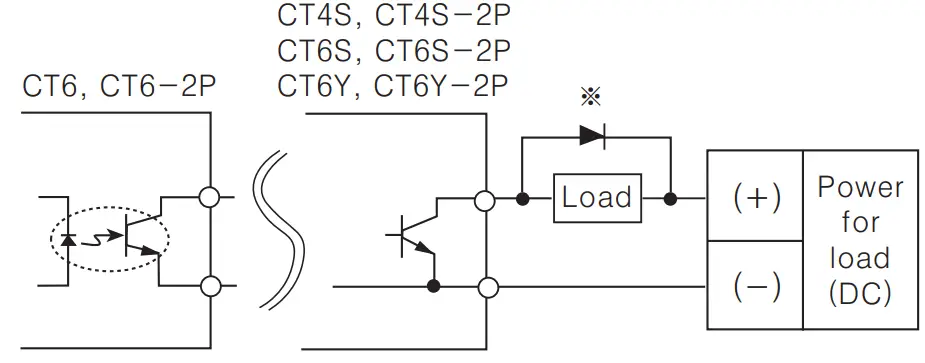
![]() Use proper load and power for load not to exceed ON/OFF capacity (Max. 30VDC 1008A) of solid—state output
Use proper load and power for load not to exceed ON/OFF capacity (Max. 30VDC 1008A) of solid—state output![]() Be careful not to apply reverse polarity of power.
Be careful not to apply reverse polarity of power.
Factory default settings
| Model→ Set item ↓ | CY6—2P CY6S—2P CY4S—2P CY6Y—2P | CY6 CY6S CY4S CY6Y | CY6—I | |
| COUNTER | Input mode | |||
| Max. counting speed | 30 cps | |||
| Output mode | — | |||
| OUT2(OUT) output time | 100 ms | — | ||
| OUT1 output time | Hold | — | ||
| Miת. reset time | 20 ms | |||
| Decimal point | No decimal point | |||
| Prescale value | 6 digit: 1.000, 4 digit: 1.00 | |||
| Memory protection | ||||
| TIMER | Time range | 6 digit: 0.01s ~ 9999.99s 4 digit: 0.01s ~ 99.99s | ||
| Up/Dowת mode | ||||
| Output mode | OND(ON Delay) | — | ||
| Output time | Hold | — | ||
| Input signal mode | 20ms | |||
| Input logic | No—voltage input(NPN) | |||
| Lock key | ||||
| Counter/Timer | Counter | |||
Error display
| Error display | Errors | Output status | How to return |
| CPU error | OFF |
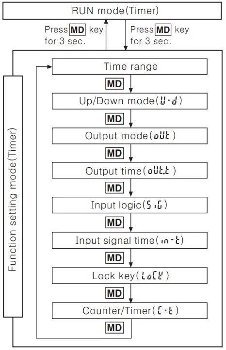
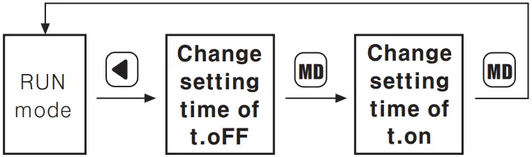
Counter mode![]() Operation mode in Counter
Operation mode in Counter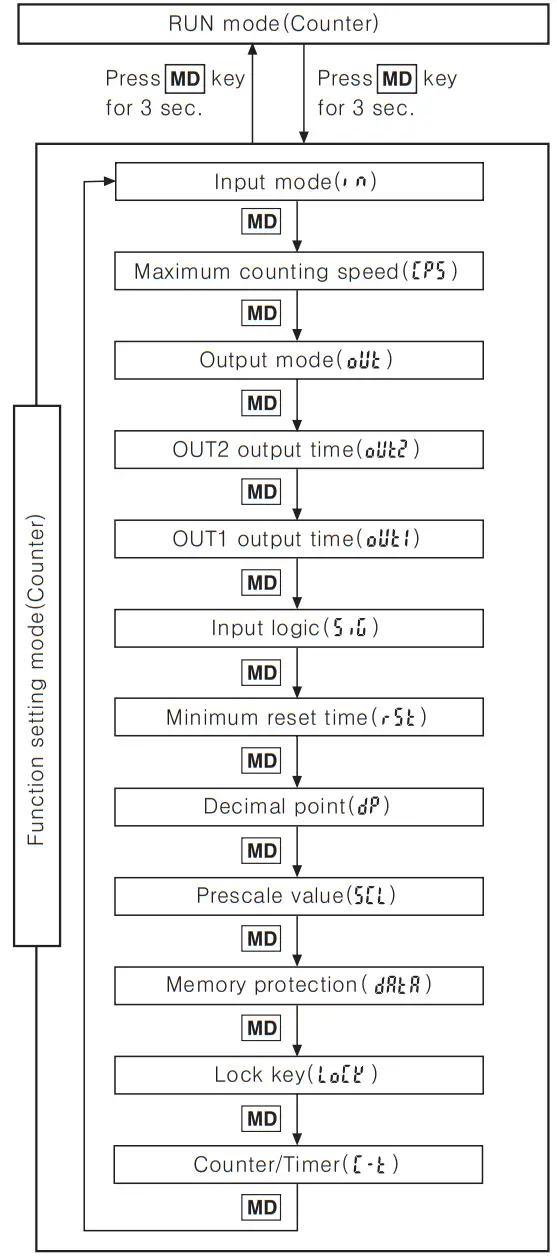
- Press key for over 3 sec., in Counter RUN mode, it advances to Counter function setting mode and press key for over 3 sec in function setting mode, it returns to RUN mode.
(Note) Be careful when it advances to function setting mode during operation, it is reset. - If no keys are touched for over 60sec., it returns to RUN mode.
- When using this unit as a timer, change as timer (
 ) in Counter/Timer setting item of function setting mode and press key for over 3 sec. then, it advances to RUN mode. (See A-21 for the specific description of Timer.)
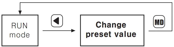
Change of setting value(Counter)![]() Change the setting value in the single preset type
Change the setting value in the single preset type
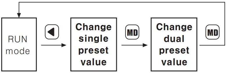
![]() Change the setting value in the dual preset type
Change the setting value in the dual preset type
![]() When register input signal during setting value change, it controls counting and output.
When register input signal during setting value change, it controls counting and output.![]() If no keys are touched for over 60sec., during setting value change, it returns to RUN mode.
If no keys are touched for over 60sec., during setting value change, it returns to RUN mode.![]() After change setting value as “0” , press
After change setting value as “0” , press ![]() or input RESET during RUN mode, output will be maintained as OFF status.
or input RESET during RUN mode, output will be maintained as OFF status.
(When set single setting as “0” in output mode “![]() (T)” it is maintained as ON status.)
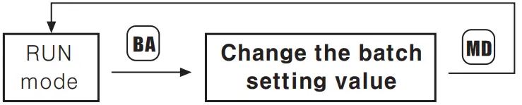
(T)” it is maintained as ON status.)![]() Change of batch setting value
Change of batch setting value
Batch counter function is only available in CT6, CT6-2P type.
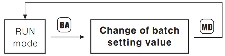
![]() If you press
If you press ![]() key in RUN mode, it will allow you to make change to the batch setting value.
key in RUN mode, it will allow you to make change to the batch setting value.
After change the batch setting value by same method as the method of Counter setting value changes by ![]() keys, it will return to RUN mode by pressing :
keys, it will return to RUN mode by pressing :![]() key.
key.
When it advances to change the batch preset value, the prior value of the batch counting is displayed.![]() Batch setting is limited to single setting mode even in dual setting model.
Batch setting is limited to single setting mode even in dual setting model.
How to set Lock key
Be sure to set the lock mode in order to protect against accidental or unauthorized key operation.![]() (Lock OFF): Cancellation of the lock mode “LOCK” OFF
(Lock OFF): Cancellation of the lock mode “LOCK” OFF![]() (Lock level 1): Lock
(Lock level 1): Lock ![]() key “LOCK” ON
key “LOCK” ON![]() (Lock level 2): Lock
(Lock level 2): Lock ![]() key “LOCK” ON
key “LOCK” ON![]() (Lock level 3): Lock (
(Lock level 3): Lock ( ![]() &
& ![]() key “LOCK” ON
key “LOCK” ON
Functing setting mode(Counter)
( ![]() key: Use the
key: Use the ![]() or
or ![]() key to change the setting)
key to change the setting)
| Setting mode | How to set ( | |
| Input mode ( | ||
| Maximum counting speed ( | ||
| Output mode ( | •Up or Down input mode | |
| OUT2 output time( | ||
| Input logic ( | The input logic is not changed with C and input 0 key, because it is under confirmation state of the prior input logic. | |
| Min. reset time ( | ||
| Decimal point ( | •6 Digit | |
| Prescale value ( | 6Digit : 0.001 — 99.999 4Digit : 0.01 — 9.99 | |
| Memory protection ( | ||
| Lock key ( | ||
| Counter/Timer ( | ||
![]() When selecting the “
When selecting the “![]() ” output mode and if 1 keeps is used, the output may not operate normally because of response time of the contact. In this case,be sure to use the solid state output.
” output mode and if 1 keeps is used, the output may not operate normally because of response time of the contact. In this case,be sure to use the solid state output.![]() In function setting mode, no external input signal will be accepted and the output will stay in the OFF
In function setting mode, no external input signal will be accepted and the output will stay in the OFF![]() There are no output mode and output time setting mode(OUT1, OUT2) of function setting mode in CT6Y~1, CT6S—I, CT6~I models.
There are no output mode and output time setting mode(OUT1, OUT2) of function setting mode in CT6Y~1, CT6S—I, CT6~I models.
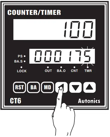
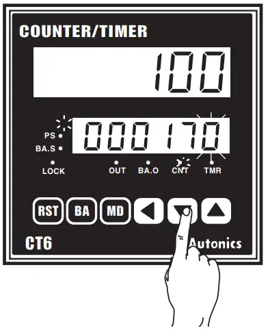
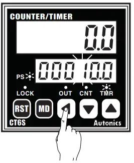
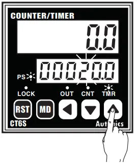
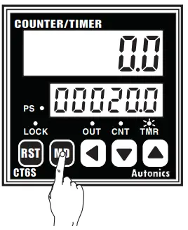
How to change counter setting![]() Change the setting value of single preset type(CT6)
Change the setting value of single preset type(CT6)
• To change the setting value from 175 to 180.
- Press
 key to advance in setting value change mode. Previous setting value is displayed and the first digit 5 flashes. (PS LED ON)
- Change “5” to “0” by press
 key 5 times and shift to the second digit by press key once.
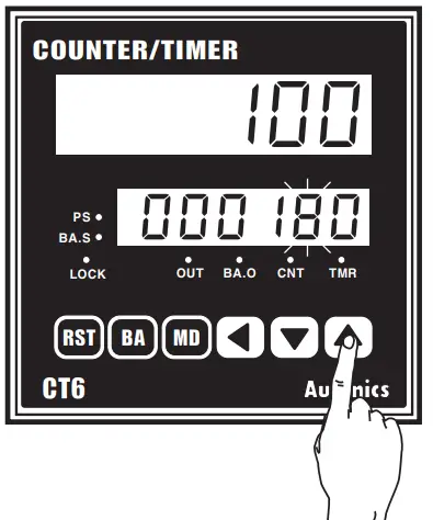
- Change “7” to “8” by pressing
 key once.
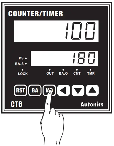
- Press key to complete the change of setting value and it returns to RUN mode. (PS LED OFF)

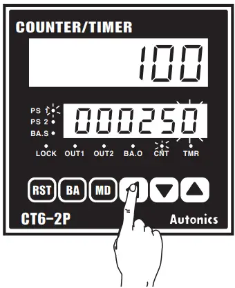
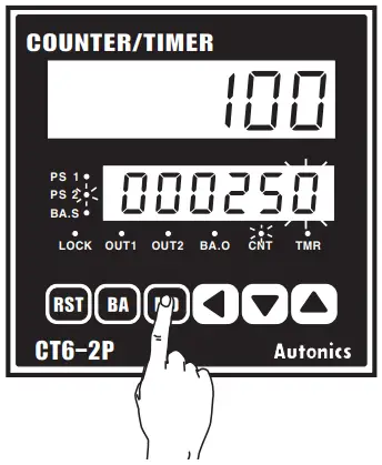
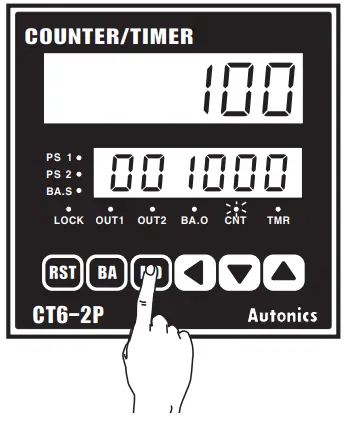
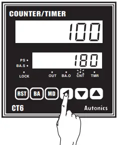
Change the setting value of dual preset type(CT6-2P)
• How to change in the dual preset type To change the dual setting value from 500 to 1000 when the single setting value is 250 and the dual setting value is 500.
- Press key to enter in status of changing setting value. The prior setting value will be displayed and “0” will flash. (PS1 LED ON, PS2 LED OFF)

- The single setting value is not changed. Move to the change of dual setting value by pressing key. The prior dual setting value “500” is displayed and the “0” will flash.

- Change “500” to 1 000″ using keys. (It is same with change of single PRESET counter setting value.)

- Press key to complete the change of setting value and it returns to RUN mode. (PS1 LED OFF, PS2 LED OFF)


![]() If no keys are touched for over 60sec.. during setting value change, it returns to RUN mode.
If no keys are touched for over 60sec.. during setting value change, it returns to RUN mode.![]() After change setting value as “0”, press E) or input RESET during RUN mode, output will be maintained as OFF status.
After change setting value as “0”, press E) or input RESET during RUN mode, output will be maintained as OFF status.
(When set single setting as “0” in dual setting type with output mode “fr (T)” single output is maintained as ON status.)![]() Whenever press 0 key during setting value change, the flashing digit shifts.
Whenever press 0 key during setting value change, the flashing digit shifts.

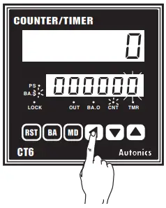
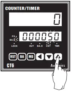
Batch counter function
![]() Change the setting value of Batch counter
Change the setting value of Batch counter
• In case of setting Batch setting value as ’50”
- Press
 key in RUN mode, it advances to Batch setting value mode. (BA.S LED ON)
 Then, the first digit “0′ flashes and others light on.
 - Press key once to advance to the second digit Of Setting display part.

- Change “5 to ‘0” by press key 5 times.

- Press key, it completes to set Batch setting value and returns to RUN mode. (BA.S LED OFF)

 Then, the first digit “0′ flashes and others light on.
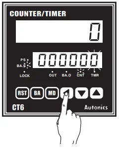
![]() Batch Counter function is only in CT6 and CT6-2P.
Batch Counter function is only in CT6 and CT6-2P.![]() When advance to Batch setting. if no key is touched for 60sec.. it will return to Counter operation mode.
When advance to Batch setting. if no key is touched for 60sec.. it will return to Counter operation mode.
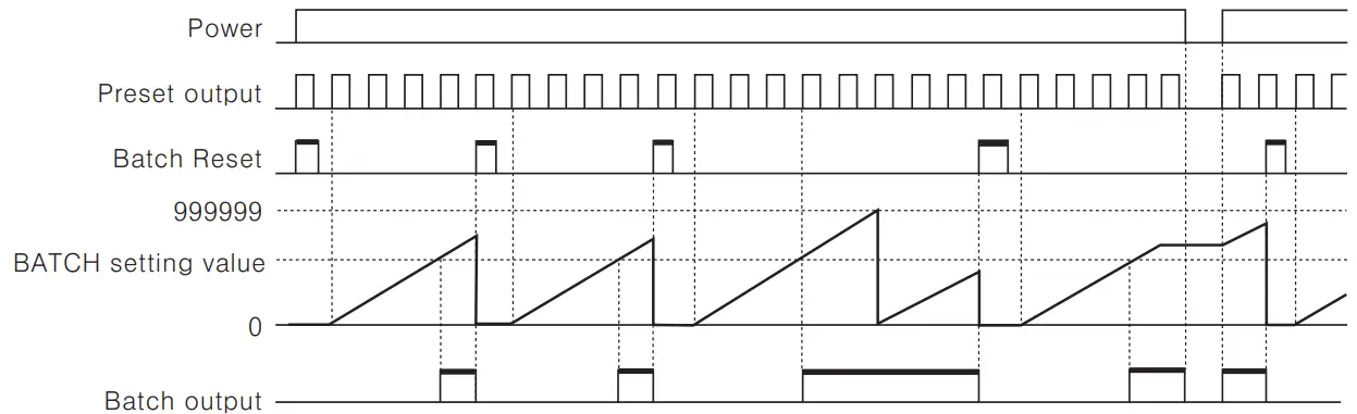
Batch Counter function(CT6)
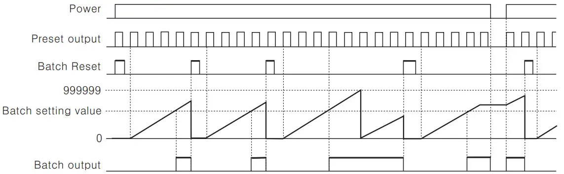
![]() When Batch counting value reaches to Batch setting value. Batch counting value is continuously increased and Batch output remains in the ON state until Batch reset is applied.
When Batch counting value reaches to Batch setting value. Batch counting value is continuously increased and Batch output remains in the ON state until Batch reset is applied.![]() When the Batch output turns on and if the power turns off and then turns on again. the Batch output remains in the ON state until the Batch reset signal is applied.
When the Batch output turns on and if the power turns off and then turns on again. the Batch output remains in the ON state until the Batch reset signal is applied.![]() When the Batch counting value counts over 999999. it resets to “0”. and it counts up again. elf Batch setting value is “0 (ZERO)”. Batch counting value counts up. but output remains in the OFF status.
When the Batch counting value counts over 999999. it resets to “0”. and it counts up again. elf Batch setting value is “0 (ZERO)”. Batch counting value counts up. but output remains in the OFF status.![]() The Batch counting value is not changed by front
The Batch counting value is not changed by front ![]() key or external reset signal.
key or external reset signal.![]() In case of CT6-2P. “Count—up” refers to operation state of output when the counting value is reached to the preset value.
In case of CT6-2P. “Count—up” refers to operation state of output when the counting value is reached to the preset value.![]() Reset the Batch counting value
Reset the Batch counting value
When the external terminal of Batch RESET is short—circuited. the Batch counting value is reset. But the terminal number of Batch Reset is different depending on the input logic.![]() When Voltage input type (PNP) is selected. please make terminal numbers 10 and 14 short—circuited.
When Voltage input type (PNP) is selected. please make terminal numbers 10 and 14 short—circuited.
And when No—voltage input type(NPN) is selected. please make terminal number of 11 and 14 short—circuited.![]() Check the Batch counting value
Check the Batch counting value
In order to check the Batch counting value during the Counter operation. press the ![]() key to display both the Batch counting value and preset value.
key to display both the Batch counting value and preset value.
After checking Batch counting value. it returns to RUN mode by press ![]() key.
key.![]() There is no
There is no ![]() key lock function for Batch function.
key lock function for Batch function.
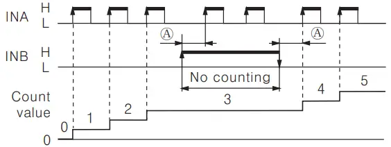
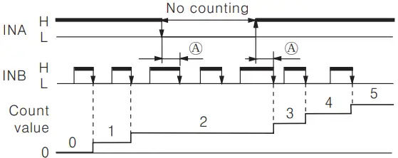
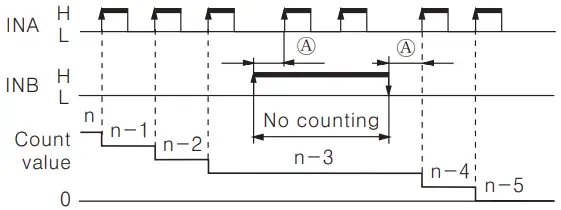
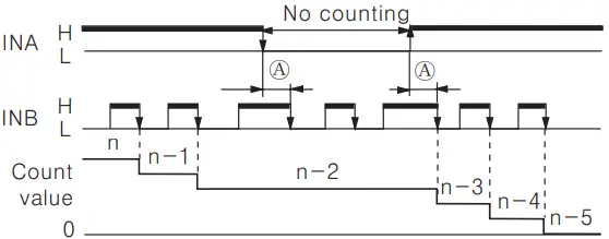
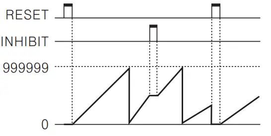
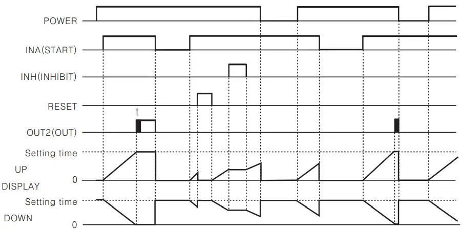
Input operation mode for counter
A: Over Min. signal width,
B: Over 1/2 of Min. signal width
 | Configure the inhibition(INB : “L” →, “H”) or Cancel the inhibition(INB : “H” → “L”) | |
 | Configure the inhibition(INB : “H” → “L”) or Cancel the inhibition(INB : “L” → “H”) | |
 | Configure the inhibition(INB : “L” → “H”) or Cancel the inhibition(INB : “H” →”L”) | |
 | Configure the inhibition (INB : “H” →, “L”) or Cancel the inhibition (INB : ‘L” →”H”) | |
Command input | 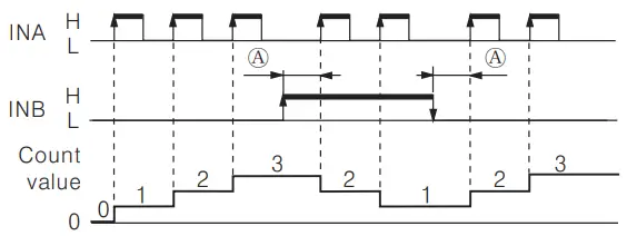 | When INB is H, count decreases. |
Individual input | 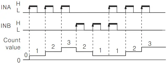 | |
Phase difference input | 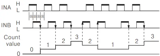 |
![]() A: Over Min. signal width, B: Over 1/2 of Min. signal width.
A: Over Min. signal width, B: Over 1/2 of Min. signal width.
If the signal width of ® or® is less than min. signal width, ± 1 of count error is occurred.![]() “‘H” and “L”
“‘H” and “L”
| Voltage iתput (PNP) | No—woltage iתput (NPN) | |
| H | 5—30VDC | Short circuit |
| L | 0—2VDC | Opeת |
![]() Min. signal width by counting speed
Min. signal width by counting speed
| Counting speed | Min. signal width |
| 1cps | 500ms |
| 30cps | 16.7 ms |
| 1kcps | 0.5 ms |
| 5kcps | 0.1 ms |
| 10kcps | 0.05 ms |
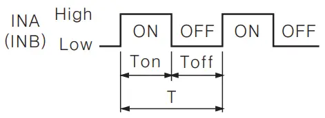
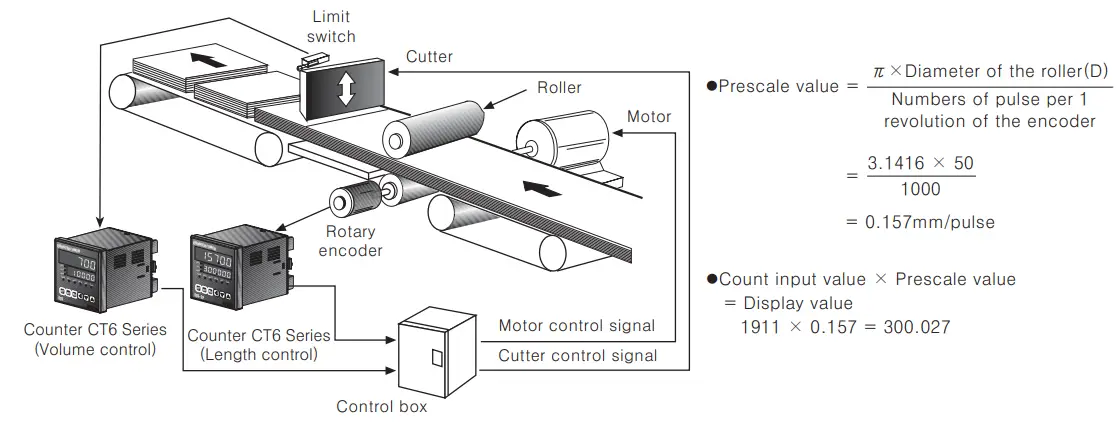
Application of Prescale function
This function is to indicate specific unit or optional multiple multiplying configured scale value by count value.
Ex1) Volume control by Counter and Limit Switch
In order to count 10 sheets of paper is produced when the cutter operates 1 time as below application, inner counter counts whenever the limit switch is operated as 1, 2, 3 times… if preset value is configured as 10 in function setting mode and indicates 10, 20, 30… multiplying scale value depending on count value.
Ex2) Length control by Counter(CT6) and Encoder
In case of cutting paper as 300mm using a 50mm diameter (D) roller connected with Encoder of 1000 pulse.
- Rectify the run—length of roller per 1 pulse, it is 0.157 mm. (Refer to formula of prescale value.)
- Configure the value as a prescale value(
 ) and 300mm of the cutting length as preset value of counter. The decimal point setting(
 ) function is not used.
 - Counter counts as 0.157 mm per 1 pulse, indicates 300mm and outputs when 1,911 pulse is inputted. But when selecting ”
 ” in decimal point setting () mode and set preset value of counter as 300.000 same with decimal point, 300.027 mm is indicated and outputted for inputting 1,911 of pulse. It is available to control accurately depending on decimal point.
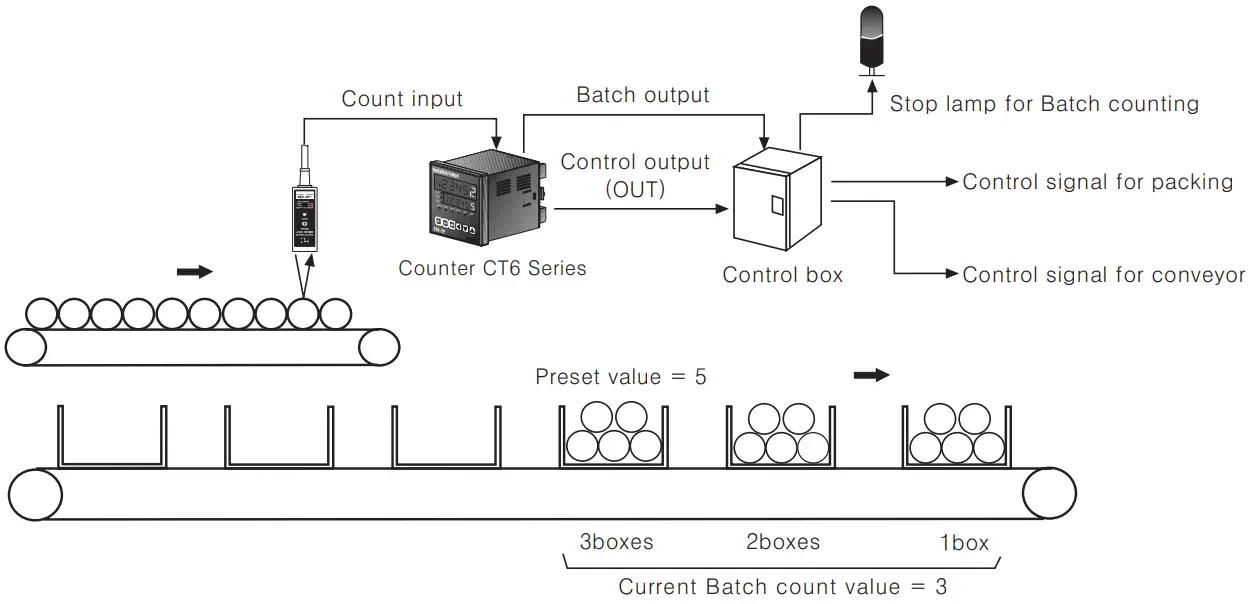
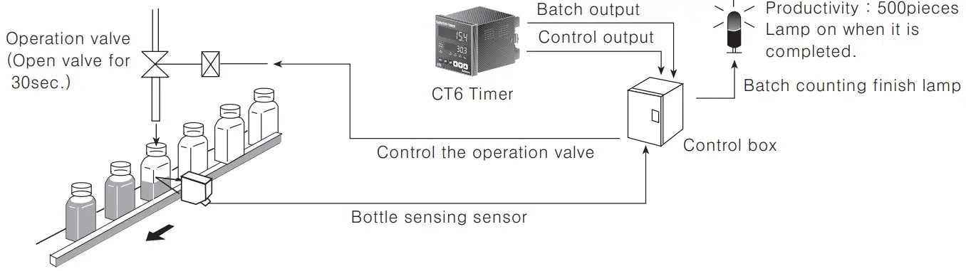
Application of Batch Counter function
In case, put 5 products in a box then pack the boxes when they reaches to 200
- Counter preset value Preset value (setting value)=”5″, Batch setting value = “200”
- When the count value of Counter reaches to the preset value”5″, the count value of Batch Counter will be increased by “1” and the control output(OUT) will be on. When the control box receives the control output (OUT), it moves the full box so the next empty box can be filled.
When the count value of Batch reaches to “200”, Batch output will be ON.
Then the control box stops conveyor and provides a control signal for packing.
Output operation mode(Counter)
![]()
| Output mode | Input mode | |||
| Up | Down Up | Down A,B,C | Operation | |
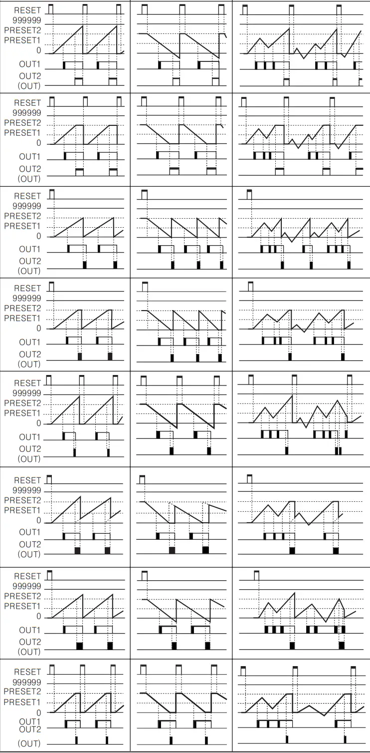 | ||||
![]() The output of single preset type is operating the same as OUT2 of dual preset type.
The output of single preset type is operating the same as OUT2 of dual preset type.![]()
| Output mode | Up/Down — A, B, C | Operation |
 | Display value ≥ Preset 1 Display value ≥ Preset 2 | |
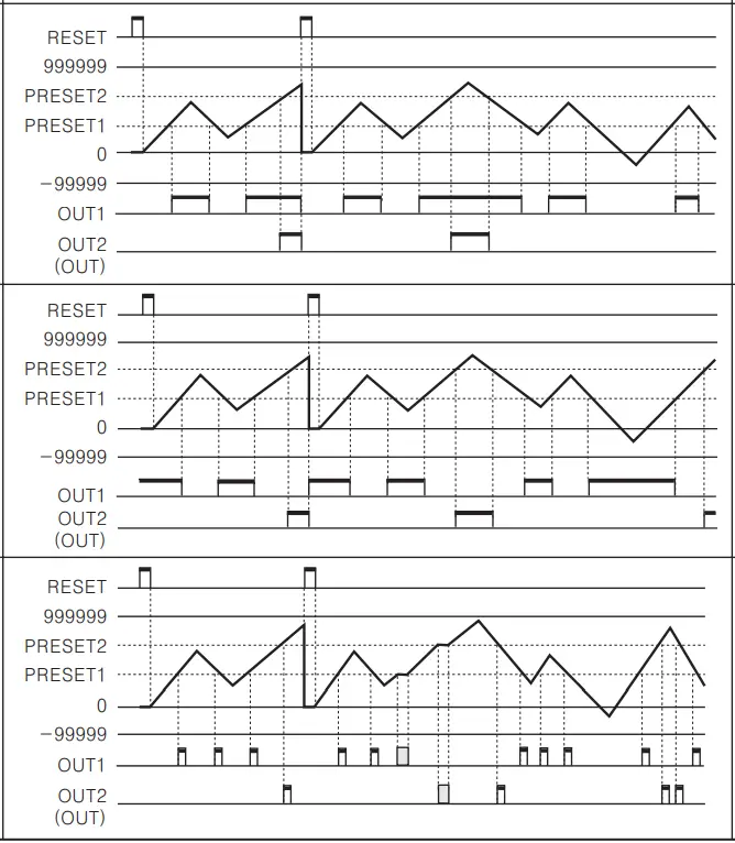
Counter operation of Indication model(CT6Y-I, CT6S-1I, CT6-1)
- In case of input mode is Up(
 )
)
- In case of input mode is Down(
 )
)
- In case of the input mode is Command input(
 ), Individual input (
 ), Phase difference input (
 )
)
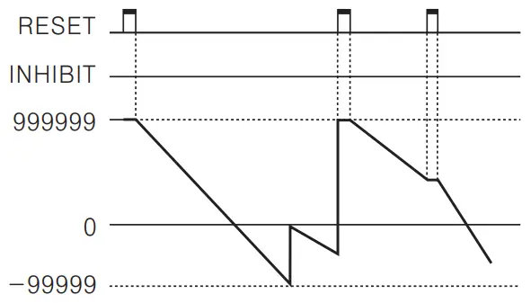
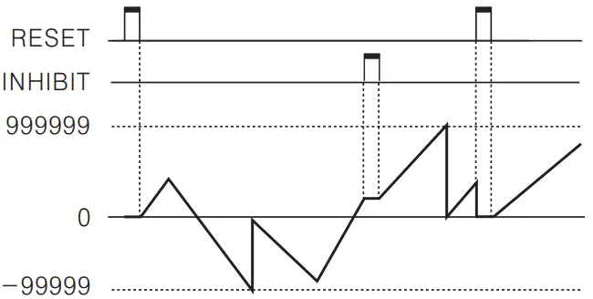
![]() If “
If “![]() ” setting value of function setting mode (count) is “
” setting value of function setting mode (count) is “![]() “, count value is reset or count value is memorized when it is “
“, count value is reset or count value is memorized when it is “![]() “.
“.![]() CT6-I has an INHIBIT terminal only.
CT6-I has an INHIBIT terminal only.
Timer mode![]() Operation mode in Timer
Operation mode in Timer
- Press key for over 3 sec., in Timer RUN mode, it advances to Timer function setting mode and press key for over 3 sec in function setting mode, it returns to RUN mode. (Note) Be careful when it advances to function setting mode during operation, it is reset.
- If no keys are touched for over 60sec., it returns to RUN mode.
- After select counter(
 ) in Counter/Timer setting item of function setting mode and press MD key for over 3 sec. then, it advances to Counter RUN mode.
Change of setting value in Timer operation![]() To change setting value in case of the output is not FLK
To change setting value in case of the output is not FLK
![]() To change setting value in case of the output is not FLK
To change setting value in case of the output is not FLK
 When dual preset type is used for timer, the setting time is limited as one and only OUT 2 is operated.
- If no keys are touched for over 60sec., after advance to setting value change mode, it returns to RUN mode. Be careful not to press key, output is not operated and same result can occur when press key after OFF power and ON again in change mode after advance to change mode, in case, output mode is OND.2, FLK.2.
 When dual preset type is used for timer, the setting time is limited as one and only OUT 2 is operated.
![]() Change the batch setting value
Change the batch setting value
- Press key in RUN mode, it advances to Batch setting value change mode. Press key after change Batch setting value same as counter setting value change by keys, it completes to change Batch setting value and advances to RUN mode. When it advances to Batch setting value change mode, it displays previous Batch count value.
- Press key to return to RUN mode after advance in Batch setting value change mode.
![]() Batch setting is limited to single setting mode even in dual setting model.
Batch setting is limited to single setting mode even in dual setting model.
Time range
- 6 Digit type Time range
Time range Function setting mode Timing display Preset display 0.01s to 9999.99s 

0.1s to 99999.9s 
1s to 999999s 
0.01s to 99m 59.99s 

0.1s to 999m 59.9s 
0.1m to 99999.9m 
1m to 999999m 1s to 99h 59m 59s 

1m to 9999h 59m 
 Model:
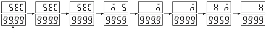
CT6Y—2P, CT6Y, CT6Y 1, CT6S 2P, CT6S, CT6S-1, CT6-2P, CT6, CT6~1 - 4 Digit type Time range
Time range Function setting mode Timing display Preset display 0.01s to 99.99s 
0.1s to 999.9s 
1s to 9999s 
1s to 99m 59s 
0.1m to 999.9m 
1m to 9999m 1m to 99h 59m 1h to 9999h  Model: CT4S—2P, CT4S
Setting function mode (Timer)
| Setting mode | How to set |
| Time range | ※ The time range for 6 digit type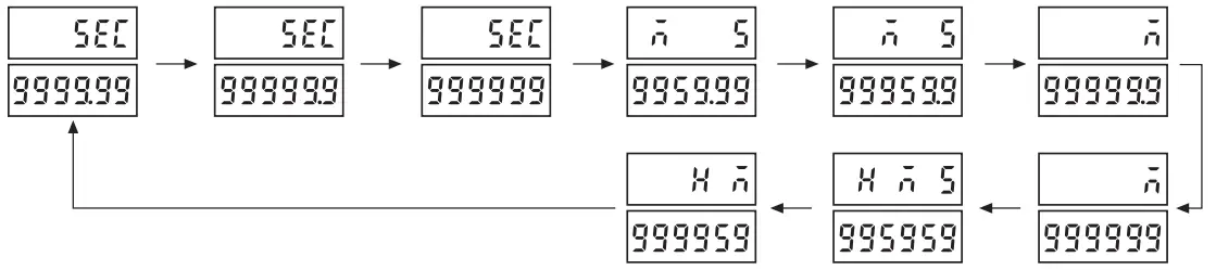 ※ The time range for 4 digit type ※ The time range for 4 digit type
|
| UP/DOWN mode | DOWN: Time proceeds from the setting value to 0 (ZERO). |
| Output mode | |
| Output time | |
| Input logic | ※ The input logic is not changed with |
| Input signal time |
※ CTS series: Min. external INA, INH, RESET signal width |
| Lock key(Lock) | |
| Counter/Timer |
![]() In function setting mode, no external input signal will be accepted and the output will stay in the OFF status.
In function setting mode, no external input signal will be accepted and the output will stay in the OFF status.![]() In case of output mode is FKL, INT, INT 1, OFD, there is no output time setting in the function setting mode.
In case of output mode is FKL, INT, INT 1, OFD, there is no output time setting in the function setting mode.![]() In the indicator type (CT6Y-I, CT6S-I, CT6-I), there are no output modes or output times in the function setting mode.
In the indicator type (CT6Y-I, CT6S-I, CT6-I), there are no output modes or output times in the function setting mode.![]() Control output operates as OUT2 in the dual preset type (CT6Y-2P, CT6S—2P, CT4S-2P, CT6-2P), and OUT1 always remains in “OFF” status. (Time setting is limited to one time.)
Control output operates as OUT2 in the dual preset type (CT6Y-2P, CT6S—2P, CT4S-2P, CT6-2P), and OUT1 always remains in “OFF” status. (Time setting is limited to one time.)![]() If no key is touched for 60 sec., in change status of setting time (PRESET value) the timer will return to RUN mode.
If no key is touched for 60 sec., in change status of setting time (PRESET value) the timer will return to RUN mode.
How to set Lock key
Be sure to set the lock mode in order to protect against accidental or unauthorized key operation.
![]() (Lock OFF): Cancellation of the lock mode “LOCK” OFF
(Lock OFF): Cancellation of the lock mode “LOCK” OFF![]() (Lock level 1): Lock
(Lock level 1): Lock ![]() key “LOCK” ON
key “LOCK” ON![]() (Lock level 2): Lock
(Lock level 2): Lock ![]() key “LOCK” ON
key “LOCK” ON![]() (Lock level 3): Lock (
(Lock level 3): Lock ( ![]() &
& ![]() key “LOCK” ON
key “LOCK” ON
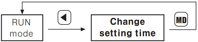
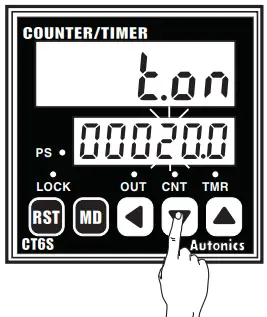
Change of the setting time of Timer![]() Change of setting time in case, the output is FLK(CT6S)
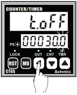
Change of setting time in case, the output is FLK(CT6S)
Change t.oFF time from 30sec. to 50sec., t.on setting from 40sec. to 20sec. (Output mode : FLK, Time range : 99999.9)
- Advance to setting time change mode by press key. Shift the flashing digit to position “3”by press key twice. (PS LED ON)

- Change “3” to I “5” by press key twice.

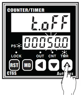
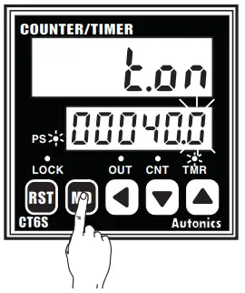
- Press key to complete t.oFF time set and advance to t.on setting time change mode.

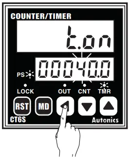
- Shift to the third I position “4” by press key twice.

- Change “5” to I “0” by press key 5 times.

- Press key to complete setting time change and return to RUN mode. (PS LED OFF)

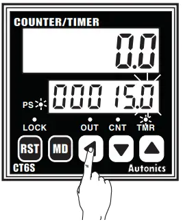
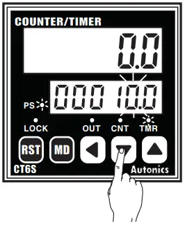
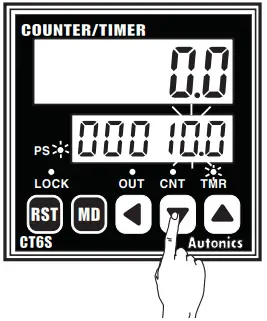
![]() Change of setting time in case of the output is not FLK(CT6S)
Change of setting time in case of the output is not FLK(CT6S)
Change the setting time from 15.0 to 20.0(Output mode : OND, Time range : 99999.9)
- Advance to setting time change mode by press key. Shift the second digit to position “5” by press key once. (PS LED ON)

- Change “5” to “0” by press key 5 times.

- Shift to the third position “1” by press key once.

- Change “1” to “2′ by press key once.

- Press key to complete setting time change and return to timer RUN mode. (PS LED OFF)

![]() When advance to setting time change mode, time will progress continuously.
When advance to setting time change mode, time will progress continuously.![]() If no keys are touched for over 60sec., after advance to setting value change mode, it returns to RUN mode. Be careful not to press key, output is not operated and same result can occur when press
If no keys are touched for over 60sec., after advance to setting value change mode, it returns to RUN mode. Be careful not to press key, output is not operated and same result can occur when press ![]() key after OFF power and ON again in change mode after advance to change mode, in case, output mode is OND.2, FLK.2.
key after OFF power and ON again in change mode after advance to change mode, in case, output mode is OND.2, FLK.2.![]() Whenever press) key during setting value change, the flashing digit shifts.
Whenever press) key during setting value change, the flashing digit shifts.![]() When use CT6Y-2P, CT4S-2P, CT6S-2P, CT6-2P as a timer, there is no dual preset function.
When use CT6Y-2P, CT4S-2P, CT6S-2P, CT6-2P as a timer, there is no dual preset function.

![]() When use CT6Y-2P, CT4S 2P, CT6S-2P, CT6-2P as a timer, there is no dual preset function,
When use CT6Y-2P, CT4S 2P, CT6S-2P, CT6-2P as a timer, there is no dual preset function,
Batch Counter function(Timer)
When it reaches the batch setting value to count the number of Time—up, the batch output will be ON. But when the output mode is “FLK”, the number of Time—ups will be 2 times because it will count both Toff, and Ton time—ups.![]() When time reaches the Toff setting time, Batch count value will be increased.
When time reaches the Toff setting time, Batch count value will be increased.
And when it reaches the Ton time, Batch count value will be increased.![]() How to set the batch setting value
How to set the batch setting value
Batch setting value is not for setting the time, it sets the count value like a counter.
Refer to A-16 for the batch setting value using as a timer, it is same as a counter.![]() Batch Counter function
Batch Counter function
![]() When count value of the number of Time—up of setting value reaches the batch setting value, the batch output is operated and the batch count value is increased until the batch reset signal is applied and the batch output returns to the OFF status.
When count value of the number of Time—up of setting value reaches the batch setting value, the batch output is operated and the batch count value is increased until the batch reset signal is applied and the batch output returns to the OFF status.![]() When the batch output turns on and if the power turns off and then turns on again, the batch output remains in the ON state until the batch reset signal is applied.
When the batch output turns on and if the power turns off and then turns on again, the batch output remains in the ON state until the batch reset signal is applied.![]() If batch setting value is “0 (ZERO)”, the batch count value is increased, but the batch output remains OFF status.
If batch setting value is “0 (ZERO)”, the batch count value is increased, but the batch output remains OFF status.![]() If batch setting value is 0 (ZERO), the batch count value counts up, but the batch output remains OFF state.
If batch setting value is 0 (ZERO), the batch count value counts up, but the batch output remains OFF state.![]() The batch count value is not changed by front
The batch count value is not changed by front ![]() key or external reset signal.
key or external reset signal.![]() Reset the Batch count value
Reset the Batch count value
When the terminal of Batch RESET is externally short—circuited, the BATCH count value will be reset. But the Batch RESET is different dependent on the input logic setting.![]() When Voltage input type (PNP) is selected, please make terminal numbers 10 and 14 short—circuited. And when No—voltage input type (NPN) is selected, please make terminal number of 11 and 14 short—circuited.
When Voltage input type (PNP) is selected, please make terminal numbers 10 and 14 short—circuited. And when No—voltage input type (NPN) is selected, please make terminal number of 11 and 14 short—circuited.![]() Check the Batch count value
Check the Batch count value
In order to check the Batch count value during the Timer operation, press the 0 key to display both the Batch count value and setting value. After check Bach count value, it returns to RUN mode by press ![]() key.
key.![]() There is no
There is no ![]() key lock function for Batch function.
key lock function for Batch function.![]() Application of Batch counter
Application of Batch counter
Fill milk into the bottle for 30 sec.(Setting time), then when 500 bottles are completed, turn Batch counting finish lamp on. (Setting time: 30 sec., Batch setting value: 500)
Output operation mode(Timer)
![]()
| Output mode | Time chart | Operation |
| Signal ON Delay(Power Reset) | 1) Time starts when INA signal turns on. When INA signal turns off, time resets. 2)Time starts when power turns on and when reset turns off during INA signal on. 3) Control output operates as retained or one—shot. 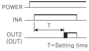 | |
 | ||
| Signal ON Delay 1(Power Reset) | 1) Time starts when INA signal turns on, if INA signal is applied repeatedly, only initial signal is recognized. 2) Time starts when power turns on and when reset turns off during INA signal on. 3) Control output operates as retained or one—shot. 4) The initial signal is effective when input INA repeatedly. 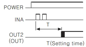 | |
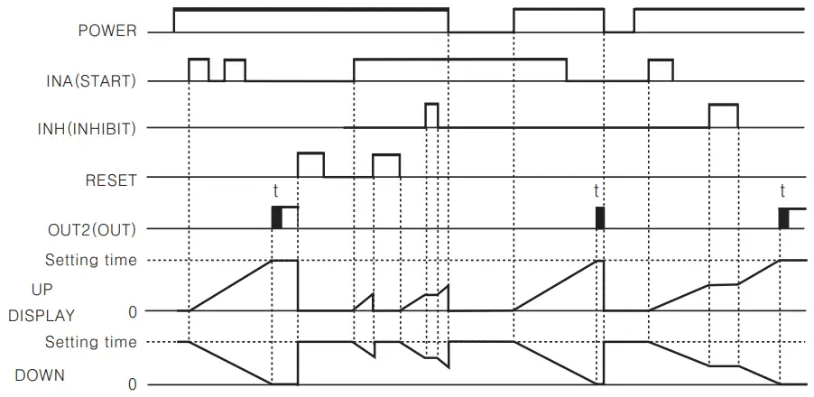 | ||
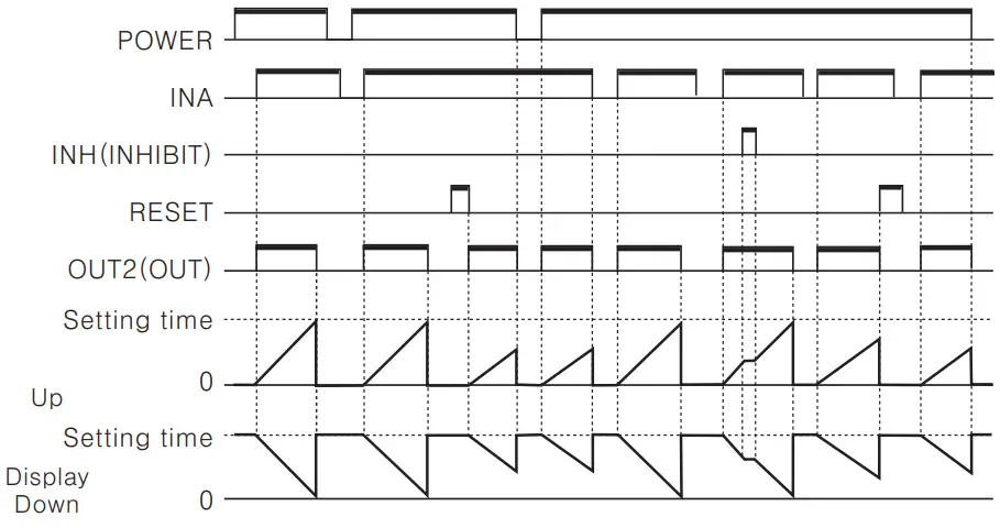
(OND.2) | Power ON Delay(Power Hold) | 1) Time starts when power turns on. (There is no INA function) 2) Time resets when reset turns on. Time starts when reset turns off. 3) Control output operates as remained or one—shot. 4) It memorizes display value at the moment of power off. |
 |
| Output mode | Time chart | Operation |
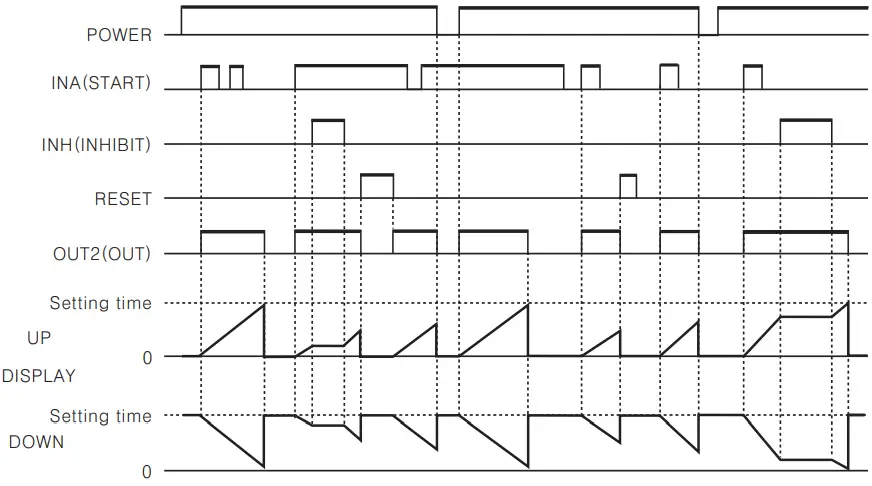
| Flicker(Power Reset) | 1) Time starts when INA signal turns on. If INA signal is applied repeatedly, only initial signal is recognized. 2)Time starts when power turns on and when reset turns off during INA signal on. 3) Control output operates as retained output, output turns off for the Toff time and turns on for the Toll time and turns on for the Ton time repeatedly. Ta+Tb=Toff setting time 4) The Ton time and the Toff time must be set individually. 5) FLK output mode has retained output. 6) In case of using the contact output, min. setting time must be set over 100 ms. 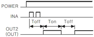 | |
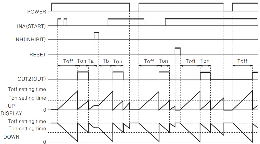 | ||
| Flicker l(Power Reset) | Mime starts when INA signal turns on. II INA signal is applied, repeatedly only initial signal is recognized. 2) Time starts when power turns on and when reset turns off during INA signal on. 3) Control output operates as retained output. In case of using the contact output, min. setting time must be set over 100 ms. 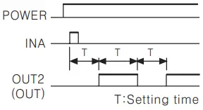 | |
Retained output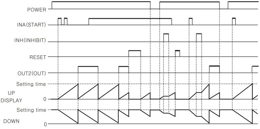 | ||
One-shot output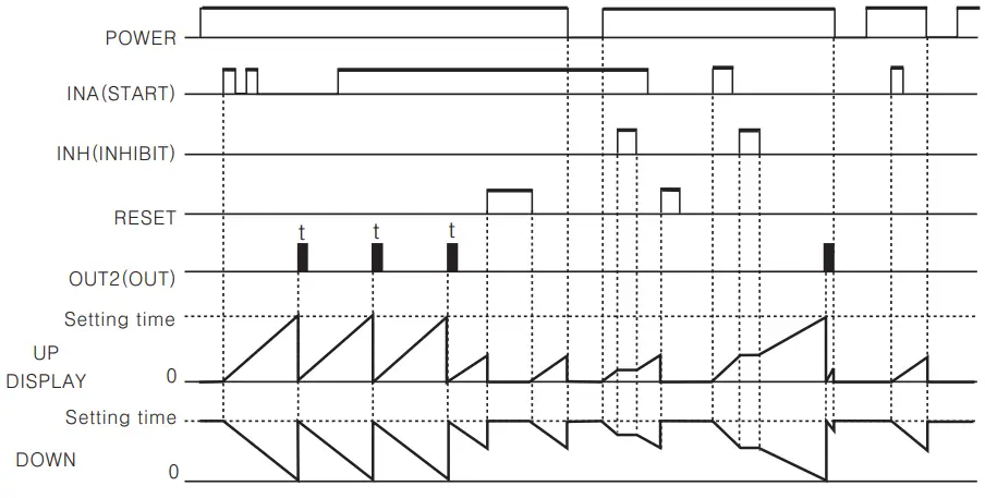 | 1) Time start s when INA signal turns on, if INA signal is applied repeatedly, only initial signal is applied. 2) Time starts when power turns on and when reset turns off during INA signal on. 3) Control output operates as one—shot. In case of using the contact output, min. setting time must be set over 100 ms. 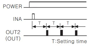 |
| Output mode | Time chart | Operation |
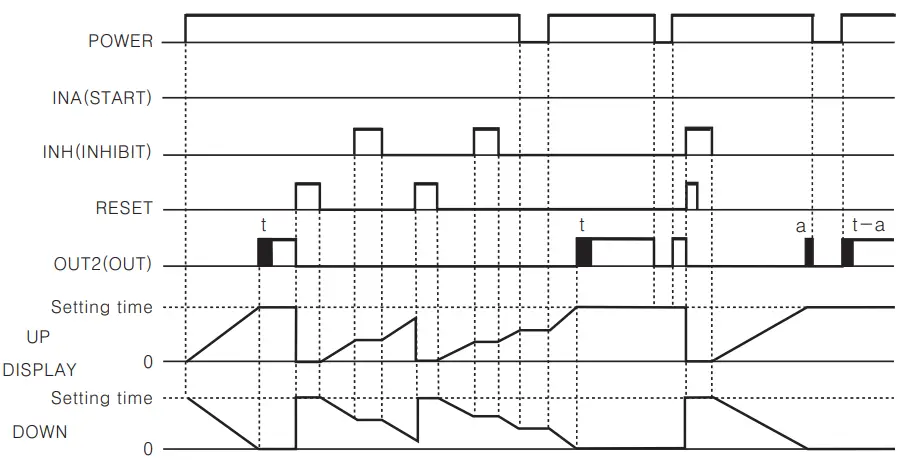
| FLICKER 2(POWER HOLD) | 1) Time starts when INA signal turns ON. If INA signal is applied repeatedly, only initial signal is recognized. 2) Control output operates as retained. 3) Control output will be reversed when it reaches to setting time. (At the initial start, OUT2 control output is OFF.) 4) In case of using the contact output, min. setting time must be set over 100ms. 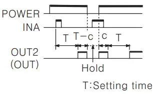 | |
Retained output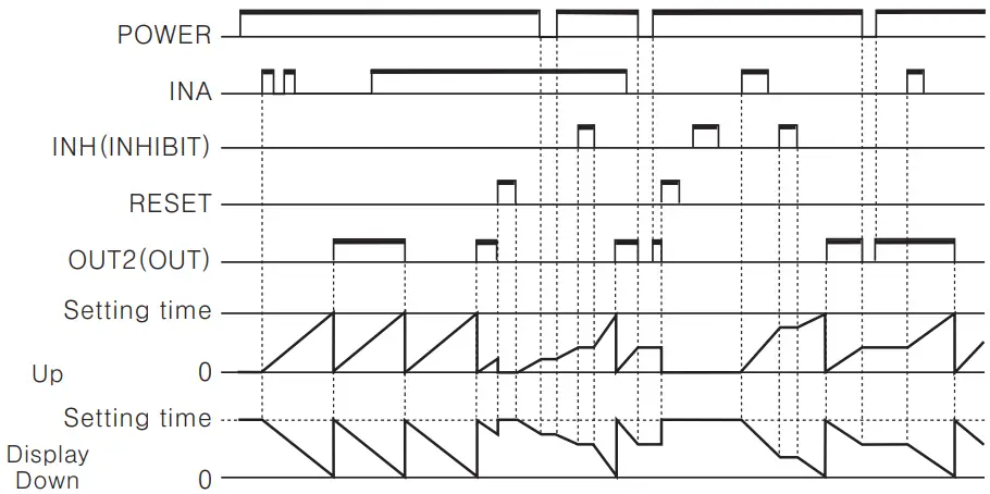 | ||
One-shot output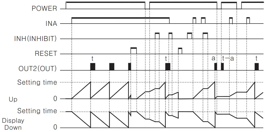 | 1)Time starts when INA signal turns ON. If INA signal is applied repeatedly, only initial signal is recognized. 2)Control output operates as one—shot output when reaches to the setting time. 3)Time starts when power turns ON and when reset turns OFF during INA signal on. 4)In case of using the contact output, min. setting time must be set over 100 ms. 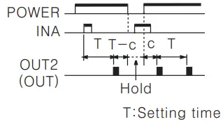 | |
 (INT) (INT) | INTERVAL(POWER RESET/SIGNAL RESET) | 1) During INA is ON, Time starts and control output turns ON. When it is reaches to setting time, the indication value and control output will be reset automatically. 2) When INA is OFF, time resets. 3) During INA signal on Power OFF: Processing time and control output Reset Power ON: Time Reset Reset ON: Processing time and control output Reset Reset OFF: Time Reset 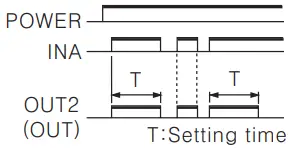 |
 |
![]() Power RESET: There is no memory protection. (Initialize the indication value when power is off.)
Power RESET: There is no memory protection. (Initialize the indication value when power is off.)![]() Power Hold: There is memory protection. (Memorize the indication value for a moment of power—off, indicate the memorized indication value when power is applied.)
Power Hold: There is memory protection. (Memorize the indication value for a moment of power—off, indicate the memorized indication value when power is applied.)
| Output mode | Time chart | Operation |
| Interval 1 (Power Reset) | 1) Control output turns ON and time starts when INA signal turns ON. 2) If INA signal is applied repeatedly, only initial signal is recognized. 3) When it reaches to setting time, indication value and control output are reset automatically. 4) Time starts when power turns ON and when reset turns OFF during INA signal on. 5) Control output is ON when time is progressing. 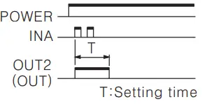 | |
 | ||
| Signal OFF Delay(Power Reset) | 1) If INA is ON, control output remains ON. 2) When INA signal is OFF, time processes. 3) When it reaches to setting time, indication value and control output are reset automatically. 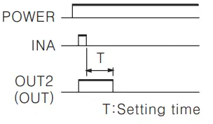 | |
 |
![]() Power Reset: There is no memory protection. (Initialize the indication value when power is off.)
Power Reset: There is no memory protection. (Initialize the indication value when power is off.)
Timer operation of Indication model(CT6-1, CT6S-0![]() There is memory protection.(Memorize the indication value when power is off. when power is on, the stored indication value will be displayed.)
There is memory protection.(Memorize the indication value when power is off. when power is on, the stored indication value will be displayed.)
![]() There is memory protection.(Memorize the indication value when power is off. when power is on, the stored indication value will be displayed.)
There is memory protection.(Memorize the indication value when power is off. when power is on, the stored indication value will be displayed.)
Proper usage
![]() Turning power ON/OFF
Turning power ON/OFF
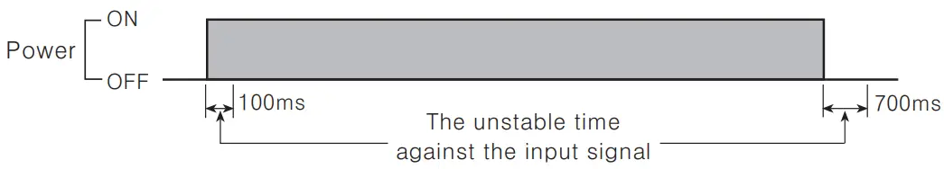
 During 100 ms after applying power, 700 ms after cutting power, it is the unstable time for rising and fall of power
- Please apply the input signal after 100 ms from power supplied and apply the power after 700 ms from power cut.
 During 100 ms after applying power, 700 ms after cutting power, it is the unstable time for rising and fall of power
![]() Input signal line
Input signal line
- Use as short a cable from the sensor to this unit as possible.
- Use shielded cable for long input line.
- Keep input cables separate from power cables.
![]() Input logic selection
Input logic selection
When selecting or changing the input logic, the power source must be cut off.
Then select the input logic according to the method of changing input logic.![]() Contact counting input
Contact counting input
If applying contact input at high speed mode(lk, 5k, 10k), it may miscount by chattering.
Therefore, set low speed mode. (1 or 30 cps)![]() Test circuit dielectric, impulse voltage and measure insulated resistor by installing in control panel,
Test circuit dielectric, impulse voltage and measure insulated resistor by installing in control panel,
- Separate the unit from control box circuit.
- Short—circuit all terminals in terminal block.
![]() Do not use this unit in the following places
Do not use this unit in the following places
- A Place where ambient temperature is over 55t or less than —10°C.
- .A Place where ambient humidity is over 85%RH or where condensation occurs by temperature changes.
- A Place where there is severe vibration or impact.
- .A Place where strong magnetic field or electric noise is generated.
- .A Place where strong alkali or acids are used.
- A Place where there are direct rays of the sun.
![]() Use under these conditions
Use under these conditions
- Indoors
- Maximum height 2000m
- Pollution Degree 2
- Installation category II
![]() Eleodis.com electronic components distributor
Eleodis.com electronic components distributor
All manuals and user guides at all-guides.com


