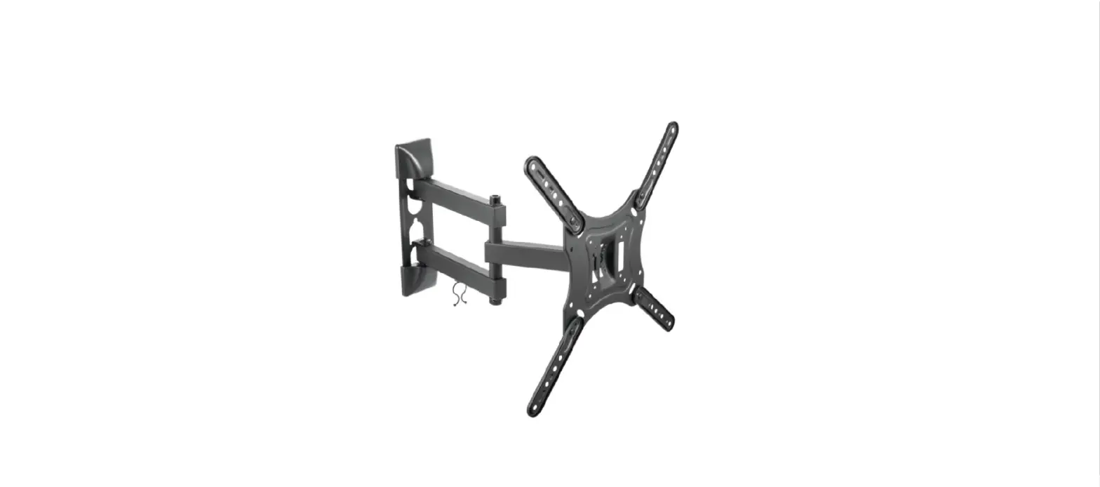
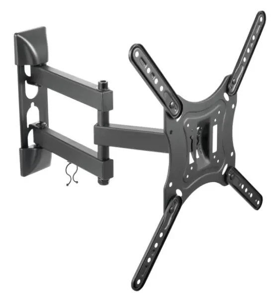
CETECH 60424N TV WALL MOUNT
Safety Information
Before you begin, carefully read and understand the instructions in this manual. Please follow the instructions in the order presented in this manual and observe all warnings and cautions.
WARNING: A Warning alerts you to the possibility of serious injury or death if you do not follow the instructions.
CAUTION: A Caution alerts you to the possibility of damage to or destruction of the equipment if you do not follow the corresponding instructions.
WARNING: Failure to provide adequate structural strength for this component can result in physical injury and/or damage to equipment. It is the installer’s responsibility to make sure the structure to which this component is attached can support four times the combined weight of all equipment. Reinforce the structure as required before installing the component.
WARNING: This wall or ceiling mount is intended for use only with the maximum weights indicated. Use with products heavier than the maximum weights indicated may result in the collapse of the mount and its accessories causing possible injury. This mount has been tested to support 80 lbs. (36 kgs). Do not exceed this weight.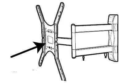
This mount has been tested to support a television with a maximum 47 in. (119 cm) diagonal screen and a weight up to 80 lbs. (36 kgs.)
WARNING: Observe all safety measures at all times during the installation of this product. Use proper safety gear and tools during the installation process to prevent physical injury.
CAUTION: Do not install on a structure that is prone to vibration, movement or chance of impact. Doing so could result in damage to the flat panel display and/or
mounting surface.
CAUTION: Do not install near a heater, fireplace, direct sunlight or any other source of direct heat. Doing so could result in damage to the flat panel display and could increase the risk of fire.
Pre-Installation
PLANNING INSTALLATION
Compare all parts in the package with the Hardware Included and Package Contents lists in this manual. If any part is missing or damaged, do not install this wall mount system and call customer service at 1-877-527-0313 or visit www.HomeDepot.com.
This wall mount bracket is compatible with VESA 100/200/300/400 mm mounting holes: 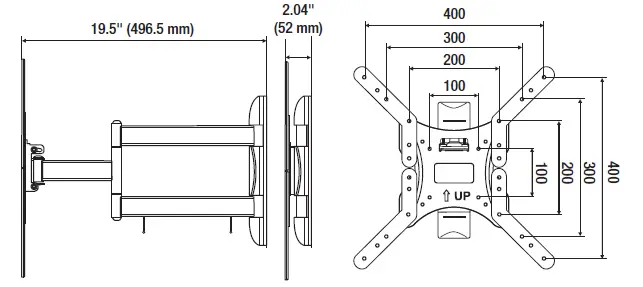
PLANNING WALL PLACEMENT
CAUTION: Ensure the wall you select is a weight-bearing wall. Failure to observe this precaution can result in serious physical injury and/or property damage. Consult a professional installer or contact customer service if you have any questions.
When selecting a wall to mount your display, keep the following in mind:
- Select a place with easy access to power outlets, cable input sources, and connections for speakers and accessories.
- Avoid direct sunlight, heat, and vibrations and do not place in the direct flow of traffic.
- Select a weight-bearing wall. The wall must be able to safely support four times the combined load of the equipment and all attached hardware and components.
PLANNING MOUNTING HEIGHT
The optimal viewing height is to center the display at eye level when seated. Many people consider this to be too low for a wall mount, and commonly use the following rule for placement:
- Position the bottom of the display no higher than eye level when seated, and the top of the display no higher than eye level when standing. Anything within these limits should normally provide a comfortable viewing experience.
ENSURING WALL STABILITY
Carefully inspect the wall area you have selected. Examine the wall surface before you begin drilling.
WARNING: Do not drill near electrical wiring and water pipes.
CAUTION: Wood studs must be no smaller than 2 x 4 in. in size.
- For concrete walls, check for damaged or loose concrete and do not drill in those areas.
- For brick wall, never drill into the mortar between blocks.
- For wood studs, locate the wall studs and drill in the center of the stud
TOOLS REQUIRED (NOT INCLUDED IN THE PACKAGING) 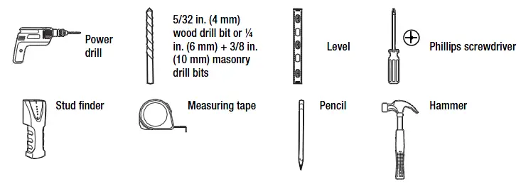
HARDWARE INCLUDED
NOTE: Hardware not shown to actual size.
NOTE: The hardware included is suitable for mounting to walls made of brick, solid concrete, or wood studs covered with drywall. If your mounting situation is different, please consult a qualified installer or contact customer service at 1-877-527- 0313 or visit www.HomeDepot.com.
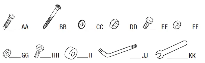
| Part | Description | Quantity |
| AA | Nylon anchor | 3 |
| BB | Lag bolt | 3 |
| CC | Lag washer | 3 |
| DD | Mounting nut (Pre-assembled on Mounting plate (C)) | 2 |
| EE | Bolt | 8 |
| FF | Nut | 8 |
| GG | M4/M5 Washer | 4 |
| HH | M4, M5, M6, M8 Screw | 4 each |
| II | Spacer | 4 |
| JJ | Hex wrench | 1 |
| KK | Wrench | 1 |
PACKAGE CONTENTS
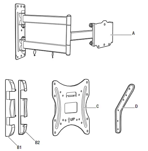
| Part | Description | Quantity |
| A | Mounting arm | 1 |
| B1/B2 | Left and right wall covers | 2 |
| C | Mounting plate | 1 |
| D | Extension rod (left and right) | 2 each |
Installation
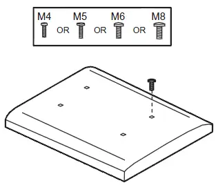
- Identifying the screw diameter to use
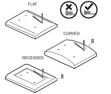
To ensure proper mounting of the brackets to your TV, this mounting system includes several sizes of screws (HH), washers (GG), and spacers (II) that can be used in various combinations. Combinations are determined by the back style of the TV (flat, curved, or recessed) and the diameter and depth of those holes.- Select the screw (HH) diameter to use by inserting the various-sized screws (HH) (M4, M5, M6, and M8) into the mounting holes in the back of your TV.

- Select the screw (HH) diameter to use by inserting the various-sized screws (HH) (M4, M5, M6, and M8) into the mounting holes in the back of your TV.
- Identifying the screw length to use
- Insert a straw or toothpick into one of the mounting holes on the back of your TV. If your TV is curved or recessed, place the proper-sized spacer (II) on top of one of the mounting holes first.
- Use a pencil to mark the depth of the mounting hole.
- Determine the proper screw length to use by comparing the mark with the various screws provided.
CAUTION: When the screw is longer than the mark, choose a shorter screw.
- Marking the mounting holes
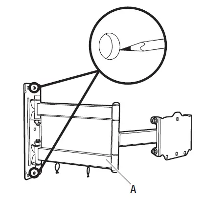
- Use the holes in the mounting arm (A) as a template to mark the mounting hole locations for attaching the mounting arm (A) to the wall.

- Use the holes in the mounting arm (A) as a template to mark the mounting hole locations for attaching the mounting arm (A) to the wall.
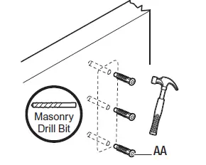
- Drilling mounting holes in concrete/brick wall
If you are installing the mounting system into wood studs, proceed to step 5.
CAUTION: Avoid drilling near electrical wiring and water pipes. The mounting system must be attached to a weight-bearing wall. Failure to observe all safety precautions can result in serious physical injury and/or property damage. Consult a professional installer or call customer service if you have any questions.
CAUTION: Do not drill into the mortar between bricks or into loose concrete.
CAUTION: Never drill into hollow brick.- Use ¼ in. or 3/8 in. masonry bits to drill mounting holes in the concrete approximately 3 in. (76 mm) in depth.
- Insert nylon anchors (AA) into the pre-drilled holes. You may have to use a hammer to gently tap the anchors fully into the wall.

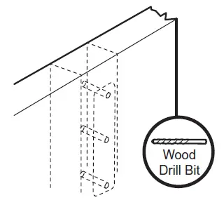
- wood studs Drilling mounting holes in
CAUTION: Avoid drilling near electrical wiring and water pipes. The mounting system must be attached to a weight-bearing wall and must be installed directly onto the center of the wood studs. Failure to observe all safety precautions can result in serious physical injury and/or property damage. Consult a professional installer orcall customer service if you have any questions.
CAUTION: Wood studs must be no smaller than 2 x 4 in. in size.- Use a commercially-available stud finder to locate the stud centers in the wall. Studs are usually spaced 16 in. apart.
- Use 5/32 in. (4 mm) wood drill bit to drill 3 in. (76 mm) pilot holes.

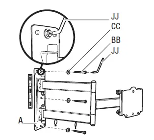
- Attaching the mounting arm to the wall
- Align the mounting armholes with the pre-drilled holes in the wall.
- Use a level to ensure that the mounting arm (A) is level on the wall.
- Attach the mounting arm (A) to the wall using lag bolts (BB) and lag washers (CC). Tighten the bolts (BB) securely using the Hex wrench (JJ).

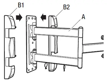
- Attaching the mounting brackets to the arm
- Place the left and right wall covers (B1 and B2) on either side of the mounting arm (A) and push the two brackets (B) together until they snap securely into place on the sides of the mounting arm (A).

- Place the left and right wall covers (B1 and B2) on either side of the mounting arm (A) and push the two brackets (B) together until they snap securely into place on the sides of the mounting arm (A).
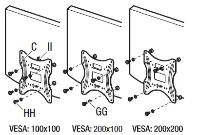
- Attaching the mounting plate to the TV (VESA 100 and 200)
This procedure describes how to attach the mounting plate to VESA 100 and 200 TVs. For VESA 300 and 400, proceed to step 9.- Align spacers (II) over the mounting holes on the back of your TV.
- Position the mounting plate (C) over the spacers (II) and attach the plate to the TV using the appropriately sized screws (HH) and washers (GG).
CAUTION: Do not overtighten the screws as this could damage your TV.
- Attaching the mounting plate to the TV (VESA 300 and 400)
- Attach the extension brackets (D) to the mounting plate (A) using bolts (EE) and
nuts (FF). - Align spacers (II) over the mounting holes on the back of your TV.
- Position the mounting plate (C) with extension brackets (D) over the spacers (II) and attach the plate (C) and brackets (D) to the TV using the appropriately sized screws (HH) and washers (GG).
CAUTION: Do not overtighten the screws as this could damage your TV.
- Attach the extension brackets (D) to the mounting plate (A) using bolts (EE) and
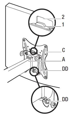
- Attaching the TV to the mounting arm
CAUTION: Use two or more people to complete this step.- Align the mounting plate (C) with the end of the mounting arm (A) and slide the tab (1) on the mounting arm (A) into the slot (2) on the mounting plate (C). Also ensure that two bolts are protruding from the two holes in the bottom of the mounting arm (A).
- Attach the mounting arm (A) to the mounting plate (C) by securing mounting nuts (DD) on the ends of the bolts protruding from the bottom of the mounting arm (A).

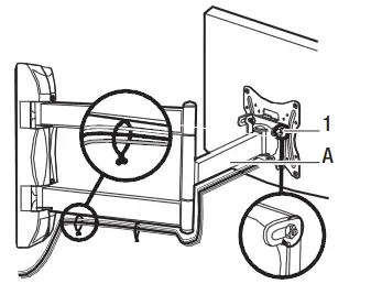
- Adjusting the angle of the TV
- Adjust the angle of the TV to a maximum of 10° by loosening the side nuts (1) on the mounting arm (A) and moving the TV to the desired angle. Re-tighten the nuts (1) after you reach the desired angle.

- Adjust the angle of the TV to a maximum of 10° by loosening the side nuts (1) on the mounting arm (A) and moving the TV to the desired angle. Re-tighten the nuts (1) after you reach the desired angle.
Questions, problems, missing parts?
Before returning to the store, call CE Tech Customer Service
8 a.m.- 6 p.m., EST, Monday-Friday
1-877-527-0313
HOMEDEPOT.COM
Retain this manual for future use.


