![]()
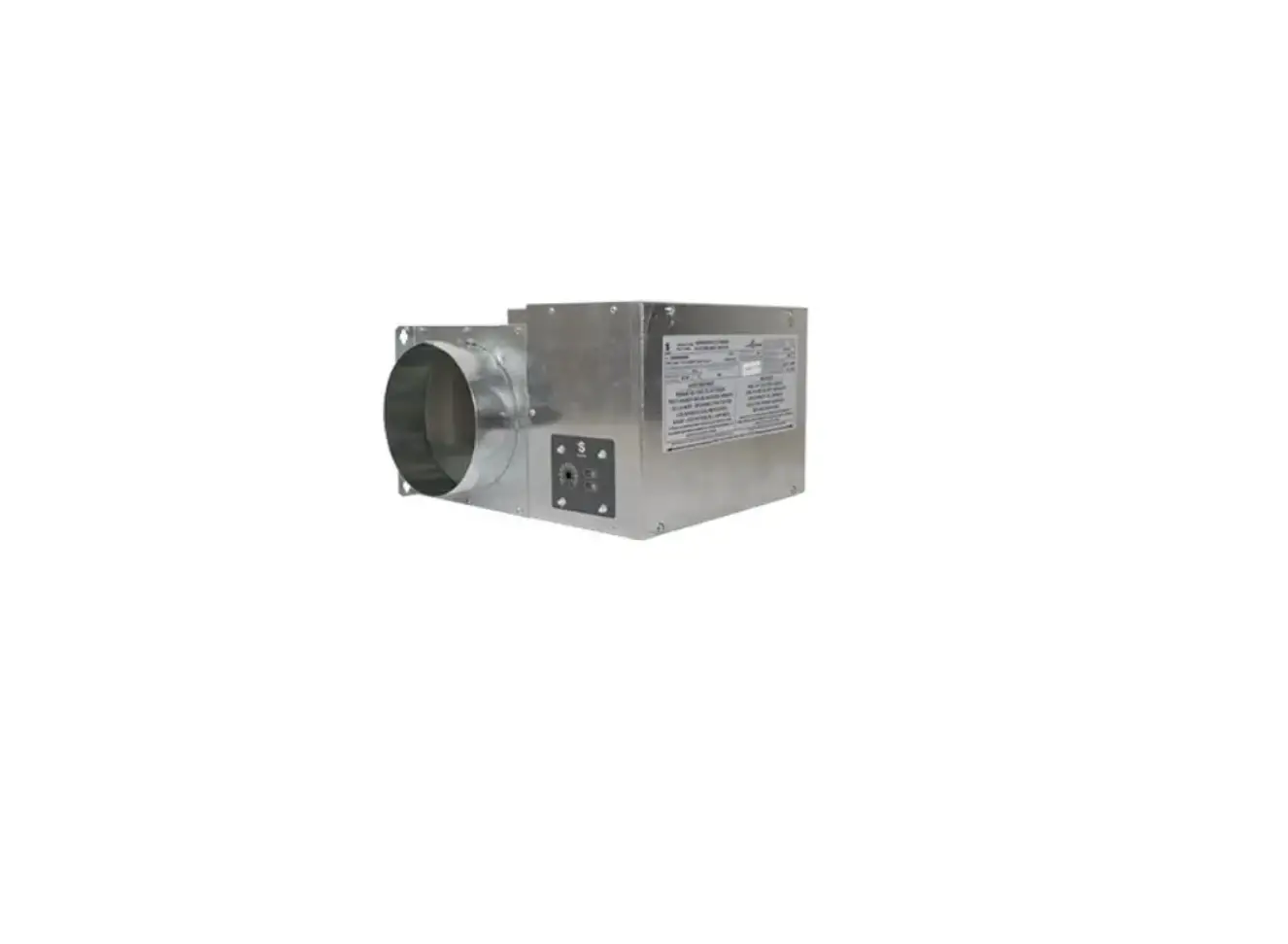
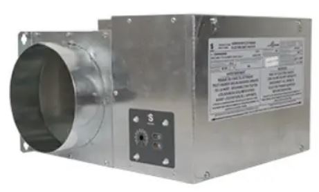
STELPRO Mua Series Make-Up Air Unit
WARNING
Before installing and operating this product, the user and/or installer must read, understand and follow these instructions and keep them handy for future reference. If these instructions are not followed, the warranty will be considered null and void and the manufacturer deems no further responsibility for this product.
This product must be installed by a qualified person and connected by a certified electrician, according to the electrical and building codes effective in your region.
The following instructions must be adhered to in order to avoid personal injuries or property damages, serious injuries and potentially fatal electric shocks.
Make sure that all screws and electrical terminal connections are tightly secured before operating the unit in case they would have loosened during transportation.
Protect the heating unit with the appropriate circuit breaker or fuse, in accordance with the nameplate.
Make sure the line voltage (volt) is consistent with that indicated on the unit’s nameplate.
This unit must be grounded.
Switch off the power at the circuit breaker/fuse before installing, repairing and cleaning the unit.
Make sure the unit is appropriate for the intended use (if needed, refer to the product catalog or a representative).
If the unit’s capacity is insufficient for the size of the house, it will be in operation continuously, and may become prematurely defective.
Respect distances and positions indicated in the installation section.
If the installer or the user modifies the unit, they will be held responsible for any damage resulting from this modification, and the CSA certification could be void.
This unit must not come into contact with a water source and must be protected from splashes (e.g. a wet mop). Do not use it if any part has been immersed. Moreover, do not turn it on or off when standing in water or if your hands are wet.
When cutting a piece of steel for the installation of the return duct, do not damage electrical wiring of the unit.
Because this unit is hot when in use, it may pose risks even in normal operation. Therefore, be careful and responsible when using it. To avoid burns, do not let bare skin touch hot surfaces. Let the unit cool down for a few minutes before handling it (it stays warm for some time after shut-down).
Never block air vents. This obstruction could lead to overheating, which could result in a fire.
Do not insert or allow foreign objects to enter any air vent as this may cause electric shocks, fires, or damages to the unit.
This unit has hot and arcing or sparking parts inside. It is not designed to be used or stored in wet areas or areas containing flammable liquids, combustible materials or corrosive, abrasive, chemical, explosive and flammable substances such as, but not limited to, gasoline, paint, chlorine and cleaning products.
Some areas are dustier than others. Thus, it is the user’s responsibility to evaluate if the filter must be changed based on it. Accumulated dirt can lead to a component malfunction or discoloration (yellowing). It may cause a fire hazard if not installed and maintained in accordance with these instructions.
Thermal protection activation indicates that the unit has been subjected to abnormal operating conditions. If the thermal protection remains activated or activates and deactivates repeatedly, it is recommended that a qualified electrician or a certified repair centre examine the unit in order to make sure it is not damaged. (Refer to the limited warranty).
If the unit is damaged or defective, cut off power supply at circuit breaker/fuse and call a certified repair centre. (Refer to the limited warranty).
Label all wires prior to disconnection when servicing controls. Wiring errors can cause improper and dangerous operation.
Note: When a part of the product specification must be changed to improve operability or other functions, priority is given to the product specification itself. In such instances, the instruction manual may not entirely match all the functions of the actual product. Therefore, the actual product and packaging, as well as the name and illustration, may differ from the manual.
LIST OF MODELS
| Model | CollaR dia. | PoweR | voltage | aMperage | flow | Noise level* |
| CoDe | IN. | KW | volTS | AMPS | Cfm | DB |
| MUa06151 | 6 | 1.5 | 120 | 12.8 | 45 @ 90 | 48 @ 56 |
| MUa0615 | 6 | 1.1/1.5 | 208/240 | 5.7/6.5 | 45 @ 90 | 48 @ 56 |
| MUa0620 | 6 | 1.5/2.0 | 208/240 | 7.5/8.5 | 45 @ 90 | 48 @ 56 |
| MUa0630 | 6 | 2.3/3.0 | 208/240 | 11.3/12.8 | 45 @ 90 | 48 @ 56 |
| MUa0845 | 8 | 3.4/4.5 | 208/240 | 16.8/19.4 | 100 @ 200 | 48 @ 58 |
| MUa0850 | 8 | 3.8/5.0 | 208/240 | 18.6/22.4 | 100 @ 200 | 48 @ 58 |
| MUa0860 | 8 | 4.5/6.0 | 208/240 | 22.2/25.6 | 100 @ 200 | 48 @ 58 |
MEASURED AT A DISTANCE OF 1 METER IN FRONT OF THE UNIT.
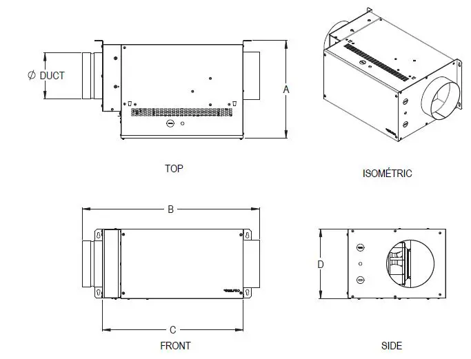
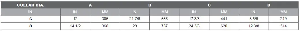
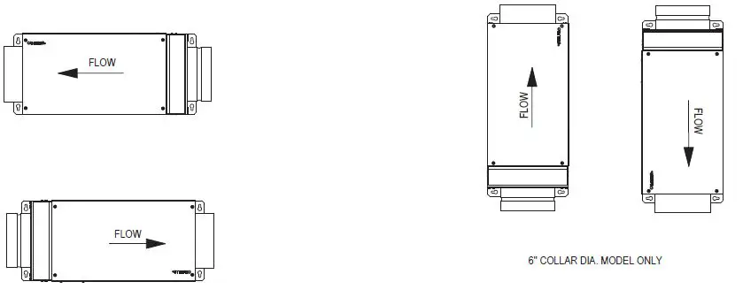
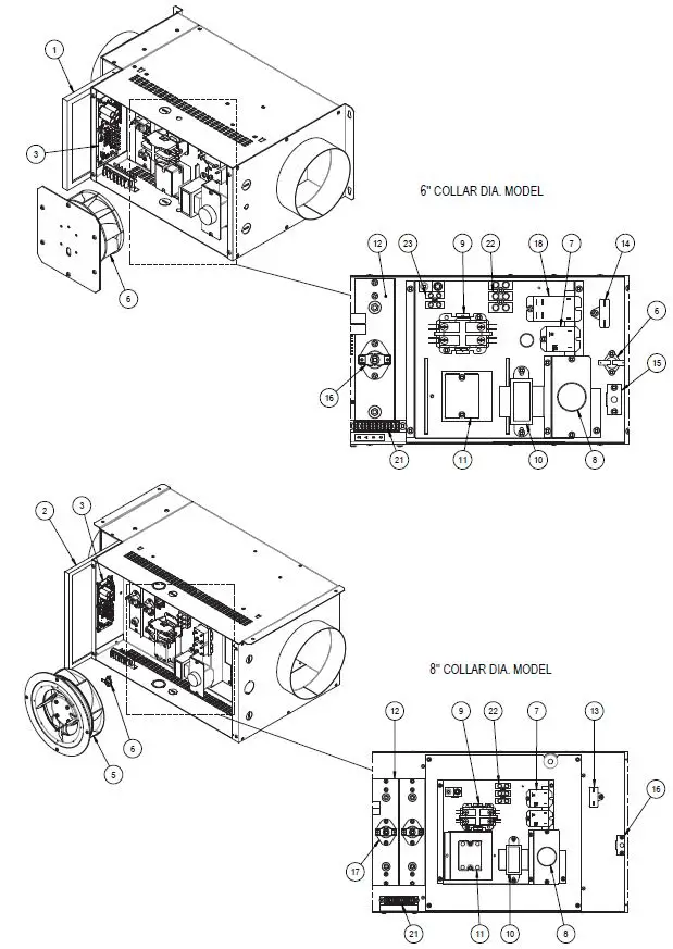
TECHNICAL DRAWINGS
MECHANICAL INSTALLATION
INSTALLING THE DEVICE
The device was designed to be installed horizontally and vertically (for the 6 in. collar dia. model only).
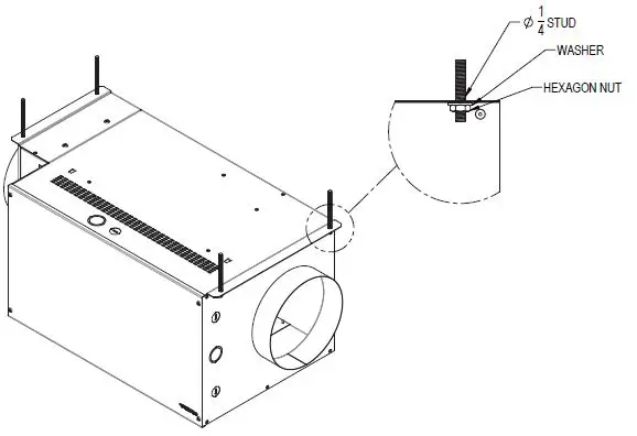
Securely attach the device to a solid support. Devices with 8-in. collars must be mounted from the ceiling using studs (not included).
CHOOSE AN APPROPRIATE LOCATION TO INSTALL THE DEVICE:
- Ideally in a service room intended for this purpose, where the temperature is maintained between 10°C and 40°C.
- Close to an exterior wall, so as to limit the length of the air inlet insulated ducts
- Away from the electrical panel and other fire hazards.
- Make sure you can easily access the inside of the device to perform maintenance (24”minimum clearance required from the main entrance door of the device).
- leave a minimum space of ½” above the device.
INSTALLING THE DUCT SYSTEM
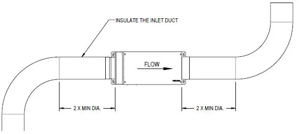
- Plan the simplest system, using the least number of elbows and joints. Keep the length of insulated ducts to a minimum to prevent choke and improve ventilation.
- Do not install elbows less than twice the diameter of the device’s duct
- Use only rigid metal ducts.
- Insulate the inlet ducts only. It is not necessary to insulate the outlet ducts.
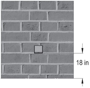
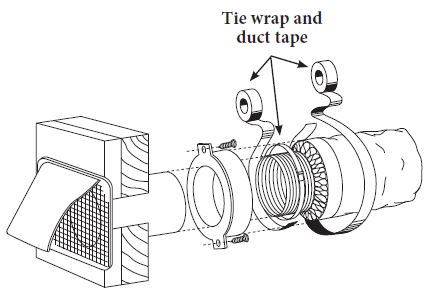
INSTALLING THE FRESH AIR INTAKE HOOD
Choose the appropriate location to install the fresh air intake hood:
- The fresh air intake hood must be installed at least 18 in. above the ground.
- Make sure the fresh air intake hood is at least 6 ft. away from the following elements: garbage can or any other contaminating source, gas meter outlet, dryer outlet, any other combustion source outlet.
- Install the fresh air intake hood at least 3 in. from the edge of the build-ing to avoid turbulence, which could cause dust to enter the hood.
- See the illustration below on how to connect the fresh air intake hood to the exterior hood (louver not included).
TYPICAL INSTALLATIONS
It is strongly recommended to read the following instructions in order to correctly install the device according to the different installation types. The two most frequently used installation methods are independent installation and installation connected to a forced air system.
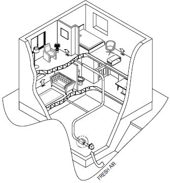
INDEPENDENT INSTAllATION (FOR HOMES HEATED WITh ELECTRIC BASEBPARDS)
This system functions independently and has its own ventilation duct system. fresh air from outside is filtered and preheated, and is then distributed by floor grills. The distribution grills are installed in the bedrooms and the main living areas (a minimum of one grill per floor, without bedroom or living room).
- It is not recommended to install any distribution grill in the kitchen or bathroom.
- Use bathroom fans and a kitchen range hood to evacuate exhaust air.
- A grill installed on the upper part of an interior wall should be at least 6 in. from the ceiling. It is important to direct the airflow toward the ceiling. The horizontal draft toward the ceiling should be approx. 3 ft. from the grill. This way, the cooler air will then cross the upper part of the room and mix with room air before descending to occupant level.
- If the grill is installed in the floor, direct the draft toward the wall.
- Measure the velocity of the air flow from the grill. If the velocity is higher than 300 ft./min., then the grill is too small. Replace it with a larger one.
flow distribution should be taken into account during duct system installation.
It is recommended to refer to the Novoclimat table below for the flow distribution of bypass ducts according to each room.
| FRESH AIR SUPPLY (CFM) | ||
| ROOM | MINIMUM REQUIRED | MAXIMUM |
| Master bedroom | 20 | 20 |
| Bedroom | 10 | 20 |
| office | 10 | 20 |
| Living room | 10 | 40 |
| unfinished basement | 10 | 40 |
| Dining room | 10 | 25 |
Refer to the table below to choose the size of the bypass ducts that run towards the grill. It is very important not to exceed the nominal duct airflow.
| ByPass duCt size vs. Flow | ||
| ROUND DUCT (IN.) | RECTANGULAR DUCT (IN.) | Maximum Flow (Cfm) |
| 4 | 2 1/4 or 3 1/4 x 10 | 40 |
| 5 | 2 1/4 or 3 1/4 x 10 | 65 |
| 6 | 4 1/4 or 4 x 10 | 110 |
INSTALLATION CONNECTING THE DEVICE TO A FURNACE
The second method consists of using the furnace distribution system to distribute fresh air. There are two methods of connecting the device to the furnace: distribution air side connection or return air side connection.
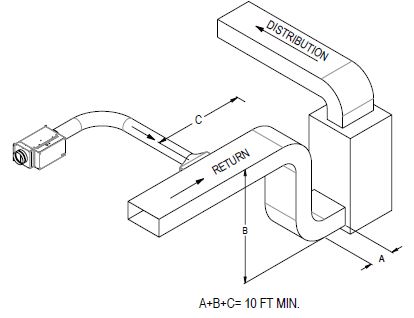
RETURN AIR SIDE CONNECTION
- Cut an opening in the furnace return air duct at least 10 ft. from the furnace duct (A+B+C).
- Connect this opening to the device according to the diagram.
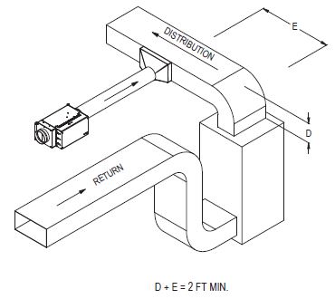
DISTRIBUTION AIR SIDE CONNECTION
Cut an opening in the furnace distribution air duct, at least 2 ft. from the furnace duct (E +D).
Connect this opening to the device.
ELECTRICAL INSTALLATION
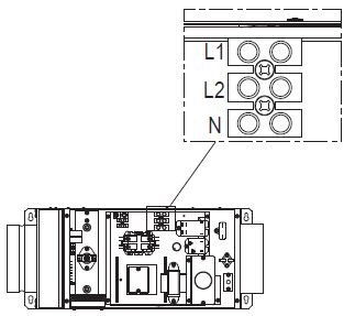
POWER CONNECTION
- Using a screwdriver, pierce the perforated hole and pass the wire through it.
- Connect the device to a 240 V electrical power supply source as illustrated.
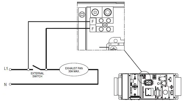
For the 6’’ model, a terminal block (30 amps max) is integrated in the unit. An auxiliary contact (external switch) can be connected to the terminal block. This will allow unit to start the exhaust fan and function simultaneously when required. Plug the exhaust fan switch in parallel with the terminals as shown in the diagram.
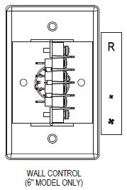
Connecting the low power control
For more convenience, the unit is connected to a main wall control. (6’’ model only).
Connect the terminal block of the unit with the one of the wall control according to the corresponding terminals.
Use #22 GA AWG wires for the connections.
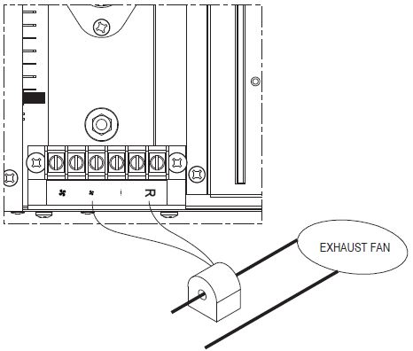
For the 8’’ model, a current switch is included with the unit. This current switch is used as an interlock between the unit and the exhaust fan by passing one of the power leeds of the exhaust fan through the hole of the current switch.
Connect the current switch to the terminal block of the unit as shown below.
Electronic control
OPERATION MODES
- MO DE (INTERMITTENT)
When the signal is lit, the unit will function in intermittent mode. Within the period of an hour, the unit operates and stops with the following
cycles: 15 minutes/45 minutes, 30 minutes/30 minutes, 45 minutes/15 minutes. - MODE (LOW SPEED/MINIMUM FLOW)
When the signal is lit, the fan runs at the speed at which the dimmer is set.
 - MODE (HIGH SPEED)
When the signal is lit, the fan runs at the maximum speed without passing through the dimmer. - STOP
The device is in stop mode when none of the signals are lit.
USER INTERFACE
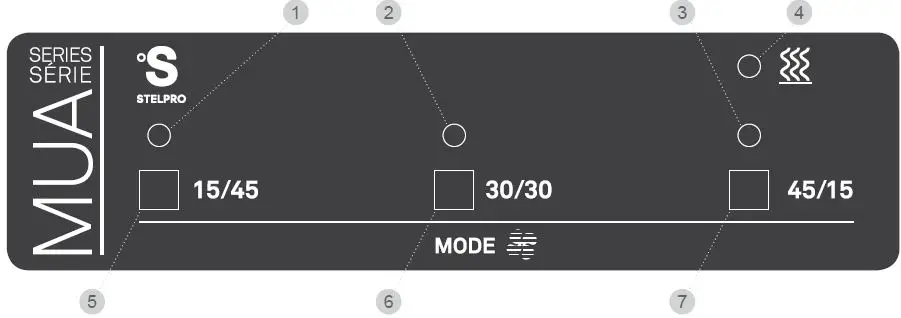
LEGEND
- 15/45 INTERMITTENT MODE green LE D: Indicates that the 15/45 intermittent mode is selected.
- 30/30 INTERMITTENT MODE green LE D: Indicates that the 30/30 intermittent mode is selected.
- 45/15 INTERMITTENT MODE green LE D: Indicates that the 45/15 intermittent mode is selected.
- HEAT ING orange LE D: Indicates that the heating cycle is in progress.
- 15/45 INTERMITTENT MODE button: Provides the selection of the 15/45 intermittent mode.
- 30/30 INTERMITTENT MODE button: Provides the selection of the 30/30 intermittent mode.
- 45/15 INTERMITTENT MODE button: Provides the selection of the 45/15 intermittent mode.
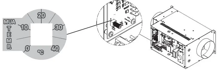
PLENUM TEMPERATURE CONTROL POTENTIOMETER
The make up air is equipped with a plenum temperature sensor. You can select the plenum temperature set point with a potentiometer installed
on the control card as shown below. The default factory set point is 20°C (68°F). You can select the set point from a temperature range between
0’C (32°F) and 40°C (104°F).
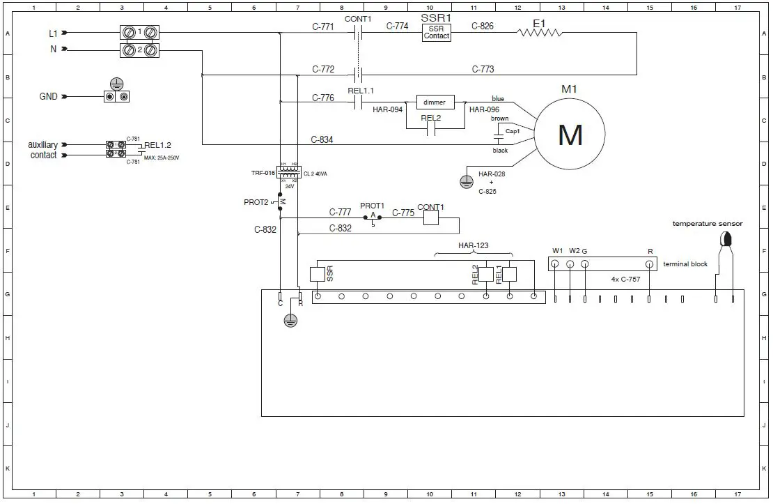
WIRING DIAGRAM
6″ MODEL /120 V
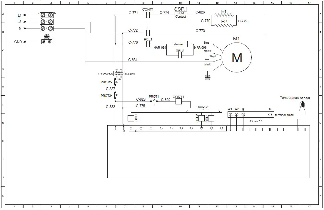
6″ MODEL/ 240 V

8” MODEL / 240 V
FLOW CONTROL
PRELIMINARY STAGE
Make sure you use a graduated pressure gauge from 0.0.W.P to 0.5 W.P.
Seal all the ducts with aluminum foil and close all the doors and windows of the house.
Turn off the bathroom fans and the kitchen range hood or any other exhaust appliances.
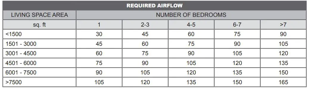
We generally recommend that you set the minimum flow to 60 cm for a standard house (2200 sq. ft. including the basement). Refer to the ASHRAE table below for the required airflow according to the size of the living space.
ADJUSTING THE CONTROLS
INDEPENDENT INSTALLATION
- Make sure all the bypass duct flaps are completely open.
- Place the manometer on a level surface and calibrate it to zero, if necessary.
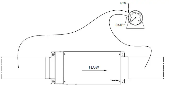
- Connect the pressure tubes according to the illustration shown below. Make sure that the pressure tubes are properly connected to the corresponding HiLow connectors on the manometer. If the manometer needle falls below zero, reverse the connections.
- Turn on the device.
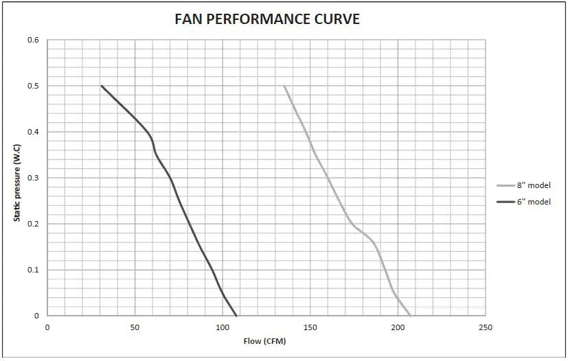
- Note the value of the static pressure of the manometer according to the airflow (refer to the device’s performance curve).
- Pre-set the minimum flow desired by turning the dimmer.
- Balance the air outlets by adjusting the opening of the bypass duct flaps.
- Re-verify the static pressure once the system has been balanced. Note that the static pressure may differ from the initial reading. Adjust the static pressure according to the desired airflow by turning the dimmer.
- Adjust the heating temperature. We recommend the temperature be set between 15°C and 20°C for optimal performance of the device and for better energy efficiency.
INSTALLATION CONNECTED TO THE FURNACE
- Repeat steps 1 to 3 from the previous section.
- Make sure that the device is working at the same time as the furnace fan.
- It is not necessary to balance the air outlets, as they use the same distribution system as the furnace, and this step should have already been done during the furnace installation.
- Adjust the desired minimum flow according to the static pressure.
- Adjust the heating temperature.
PERFORMANCE CURVE
REQUIRED POWER (WATTS) BASED ON AIR FLOW AND TEMPERATURE RISE
| AIR FLOW (CFM) – MUA06 | ||||||||||||
| ΔT (°F) | 45 | 50 | 55 | 60 | 65 | 70 | 75 | 80 | 85 | 90 | 95 | 100 |
| 5 | 73 | 81 | 89 | 97 | 105 | 113 | 121 | 129 | 137 | 145 | 153 | 161 |
| 10 | 145 | 161 | 177 | 194 | 210 | 226 | 242 | 258 | 274 | 290 | 306 | 323 |
| 15 | 218 | 242 | 266 | 290 | 315 | 339 | 363 | 387 | 411 | 435 | 460 | 484 |
| 20 | 290 | 323 | 355 | 387 | 419 | 452 | 484 | 516 | 548 | 581 | 613 | 645 |
| 25 | 363 | 403 | 444 | 484 | 524 | 565 | 605 | 645 | 685 | 726 | 766 | 806 |
| 30 | 435 | 484 | 532 | 581 | 629 | 677 | 726 | 774 | 823 | 871 | 919 | 968 |
| 35 | 508 | 565 | 621 | 677 | 734 | 790 | 847 | 903 | 960 | 1016 | 1073 | 1129 |
| 40 | 581 | 645 | 710 | 774 | 839 | 903 | 968 | 1032 | 1097 | 1161 | 1226 | 1290 |
| 45 | 653 | 726 | 798 | 871 | 944 | 1016 | 1089 | 1161 | 1234 | 1306 | 1379 | 1452 |
| 50 | 726 | 806 | 887 | 968 | 1048 | 1129 | 1210 | 1290 | 1371 | 1452 | 1532 | 1613 |
| 55 | 798 | 887 | 976 | 1065 | 1153 | 1242 | 1331 | 1419 | 1508 | 1597 | 1685 | 1774 |
| 60 | 871 | 968 | 1065 | 1161 | 1258 | 1355 | 1452 | 1548 | 1645 | 1742 | 1839 | 1935 |
| 65 | 944 | 1048 | 1153 | 1258 | 1363 | 1468 | 1573 | 1677 | 1782 | 1887 | 1992 | 2097 |
| 70 | 1016 | 1129 | 1242 | 1355 | 1468 | 1581 | 1694 | 1806 | 1919 | 2032 | 2145 | 2258 |
| 75 | 1089 | 1210 | 1331 | 1452 | 1573 | 1694 | 1815 | 1935 | 2056 | 2177 | 2298 | 2419 |
| 80 | 1161 | 1290 | 1419 | 1548 | 1677 | 1806 | 1935 | 2065 | 2194 | 2323 | 2452 | 2581 |
| 85 | 1234 | 1371 | 1508 | 1645 | 1782 | 1919 | 2056 | 2194 | 2331 | 2468 | 2605 | 2742 |
| 90 | 1306 | 1452 | 1597 | 1742 | 1887 | 2032 | 2177 | 2323 | 2468 | 2613 | 2758 | 2903 |
| 95 | 1379 | 1532 | 1685 | 1839 | 1992 | 2145 | 2298 | 2452 | 2605 | 2758 | 2911 | 3065 |
| 100 | 1452 | 1613 | 1774 | 1935 | 2097 | 2258 | 2419 | 2581 | 2742 | 2903 | 3065 | |
| 105 | 1524 | 1694 | 1863 | 2032 | 2202 | 2371 | 2540 | 2710 | 2879 | 3048 | ||
| AIR FLOW (CFM) – MUA08 | ||||||||||
| ΔT (°F) | 105 | 110 | 115 | 120 | 125 | 130 | 135 | 140 | 145 | 150 |
| 5 | 169 | 177 | 185 | 194 | 202 | 210 | 218 | 226 | 234 | 242 |
| 10 | 339 | 355 | 371 | 387 | 403 | 419 | 435 | 452 | 468 | 484 |
| 15 | 508 | 532 | 556 | 581 | 605 | 629 | 653 | 677 | 702 | 726 |
| 20 | 677 | 710 | 742 | 774 | 806 | 839 | 871 | 903 | 935 | 968 |
| 25 | 847 | 887 | 927 | 968 | 1008 | 1048 | 1089 | 1129 | 1169 | 1210 |
| 30 | 1016 | 1065 | 1113 | 1161 | 1210 | 1258 | 1306 | 1355 | 1403 | 1452 |
| 35 | 1185 | 1242 | 1298 | 1355 | 1411 | 1468 | 1524 | 1581 | 1637 | 1694 |
| 40 | 1355 | 1419 | 1484 | 1548 | 1613 | 1677 | 1742 | 1806 | 1871 | 1935 |
| 45 | 1524 | 1597 | 1669 | 1742 | 1815 | 1887 | 1960 | 2032 | 2105 | 2177 |
| 50 | 1694 | 1774 | 1855 | 1935 | 2016 | 2097 | 2177 | 2258 | 2339 | 2419 |
| 55 | 1863 | 1952 | 2040 | 2129 | 2218 | 2306 | 2395 | 2484 | 2573 | 2661 |
| 60 | 2032 | 2129 | 2226 | 2323 | 2419 | 2516 | 2613 | 2710 | 2806 | 2903 |
| 65 | 2202 | 2306 | 2411 | 2516 | 2621 | 2726 | 2831 | 2935 | 3040 | 3145 |
| 70 | 2371 | 2484 | 2597 | 2710 | 2823 | 2935 | 3048 | 3161 | 3274 | 3387 |
| 75 | 2540 | 2661 | 2782 | 2903 | 3024 | 3145 | 3266 | 3387 | 3508 | 3629 |
| 80 | 2710 | 2839 | 2968 | 3097 | 3226 | 3355 | 3484 | 3613 | 3742 | 3871 |
| 85 | 2879 | 3016 | 3153 | 3290 | 3427 | 3565 | 3702 | 3839 | 3976 | 4113 |
| 90 | 3048 | 3194 | 3339 | 3484 | 3629 | 3774 | 3919 | 4065 | 4210 | 4355 |
| 95 | 3218 | 3371 | 3524 | 3677 | 3831 | 3984 | 4137 | 4290 | 4444 | 4597 |
| 100 | 3387 | 3548 | 3710 | 3871 | 4032 | 4194 | 4355 | 4516 | 4677 | 4839 |
| 105 | 3556 | 3726 | 3895 | 4065 | 4234 | 4403 | 4573 | 4742 | 4911 | 5081 |
| AIR FLOW (CFM) – MUA08 | ||||||||||
| ΔT (°F) | 155 | 160 | 165 | 170 | 175 | 180 | 185 | 190 | 195 | 200 |
| 5 | 250 | 258 | 266 | 274 | 282 | 290 | 298 | 306 | 315 | 323 |
| 10 | 500 | 516 | 532 | 548 | 565 | 581 | 597 | 613 | 629 | 645 |
| 15 | 750 | 774 | 798 | 823 | 847 | 871 | 895 | 919 | 944 | 968 |
| 20 | 1000 | 1032 | 1065 | 1097 | 1129 | 1161 | 1194 | 1226 | 1258 | 1290 |
| 25 | 1250 | 1290 | 1331 | 1371 | 1411 | 1452 | 1492 | 1532 | 1573 | 1613 |
| 30 | 1500 | 1548 | 1597 | 1645 | 1694 | 1742 | 1790 | 1839 | 1887 | 1935 |
| 35 | 1750 | 1806 | 1863 | 1919 | 1976 | 2032 | 2089 | 2145 | 2202 | 2258 |
| 40 | 2000 | 2065 | 2129 | 2194 | 2258 | 2323 | 2387 | 2452 | 2516 | 2581 |
| 45 | 2250 | 2323 | 2395 | 2468 | 2540 | 2613 | 2685 | 2758 | 2831 | 2903 |
| 50 | 2500 | 2581 | 2661 | 2742 | 2823 | 2903 | 2984 | 3065 | 3145 | 3226 |
| 55 | 2750 | 2839 | 2927 | 3016 | 3105 | 3194 | 3282 | 3371 | 3460 | 3548 |
| 60 | 3000 | 3097 | 3194 | 3290 | 3387 | 3484 | 3581 | 3677 | 3774 | 3871 |
| 65 | 3250 | 3355 | 3460 | 3565 | 3669 | 3774 | 3879 | 3984 | 4089 | 4194 |
| 70 | 3500 | 3613 | 3726 | 3839 | 3952 | 4065 | 4177 | 4290 | 4403 | 4516 |
| 75 | 3750 | 3871 | 3992 | 4113 | 4234 | 4355 | 4476 | 4597 | 4718 | 4839 |
| 80 | 4000 | 4129 | 4258 | 4387 | 4516 | 4645 | 4774 | 4903 | 5032 | 5161 |
| 85 | 4250 | 4387 | 4524 | 4661 | 4798 | 4935 | 5073 | 5210 | 5347 | 5484 |
| 90 | 4500 | 4645 | 4790 | 4935 | 5081 | 5226 | 5371 | 5516 | 5661 | 5806 |
| 95 | 4750 | 4903 | 5056 | 5210 | 5363 | 5516 | 5669 | 5823 | 5976 | |
| 100 | 5000 | 5161 | 5323 | 5484 | 5645 | 5806 | 5968 | |||
| 105 | 5250 | 5419 | 5589 | 5758 | 5927 | 6097 | ||||
NOTE:
FOR ALL VALUES NOT SHOWN ON THIS CHART, YOU CAN USE THE FOLLOWING FORMULA
WATTS = (air flow CFM) X (delta TEMP. deg. F) /3,1
Maintenance
Minimal maintenance of the device is required for it to function optimally throughout the year. It is recommended to clean the exterior hood of the fresh air intake once per year.
Clean the air filter every four months. Shut off the device before removing the filter. Wash the air filter with mild soap and warm water. Dry the filter before reinstalling it in the device.
Disconnect the power supply to the circuit breaker/fuse before cleaning the device. Dust the device regularly to prevent dust from accumulating, which could cause the device to overheat. If the device is located in a very dusty area, use a vacuum cleaner with a dust brush attachment to clean the device.
Troubleshooting
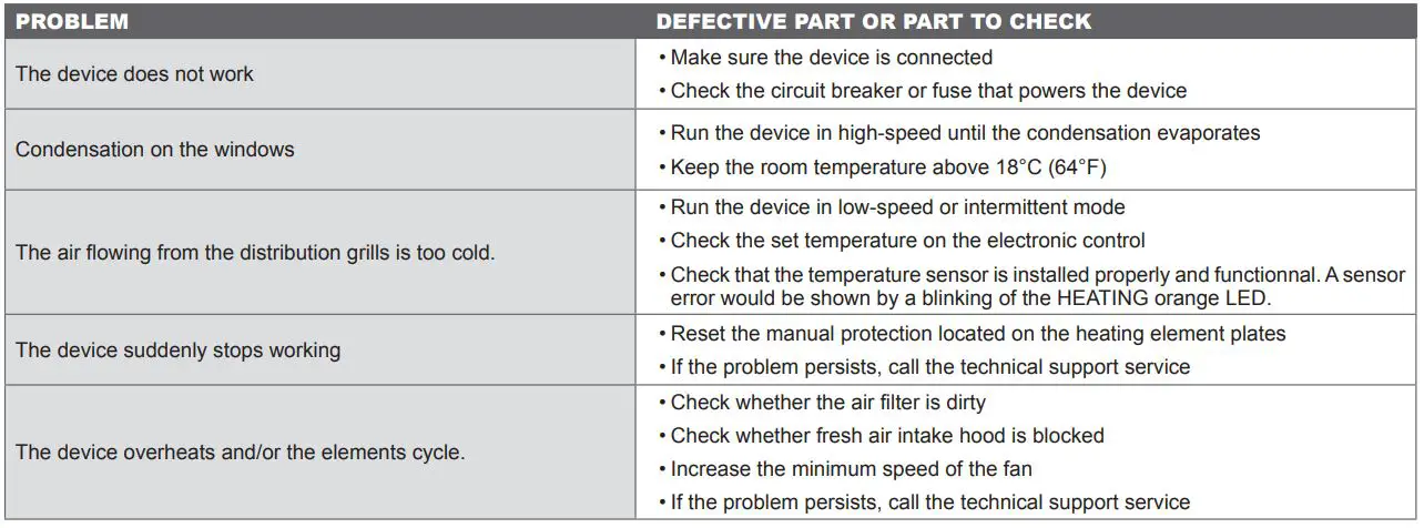
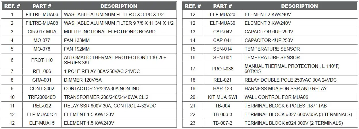
REPLACEMENT COMPONENT LIST
LIMITED WARRANTY
This limited warranty is offered by Stelpro Design inc. (“Stelpro”) and applies to the following products made by Stelpro: muA model. Please read this limited warranty carefully. Subject to the terms of this warranty, Stelpro warrants its products and their components against defects in workmanship and/or materials for the following periods from the date of purchase: 3 years (5 years on the elements). This warranty applies only to the original purchaser; it is non-transferable and cannot be extended.
CLAIM PROCEDURE
If at any time during the warranty period the unit becomes defective, you must cut off the power supply at the main electrical panel and contact 1) your installer or distributor, 2) your service center or 3) Stelpro’s customer service department. In all cases, you must have a copy of the invoice and provide the information written on the product nameplate. Stelpro reserves the right to examine or to ask one of its representatives to examine the product itself or any part of it before honoring the warranty. Stelpro reserves the right to replace the entire unit, refund its purchase price or repair a defective part. Please note that repairs made within the warranty period must be authorized in advance in writing by Stelpro and carried out by persons authorized by Stelpro.
before returning a product to Stelpro, you must have a Stelpro authorization number (RMA). To obtain it, call the customer service department at: 1-800-363-3414 (electricians and distributors – french), 1-800-343-1022 (electricians and distributors – english), or 1-866-766-6020 (consumers). The authorization number must be clearly written on the parcel or it will be refused.
CONDITIONS, EXCLUSIONS AND DISCLAIMER OF LIABILITY
This warranty is exclusive and in lieu of all other representations and warranties (except of title), expressed or implied, and Stelpro expressly disclaims and excludes any implied warranty of merchantability or implied warranty of fitness for a particular purpose.
Stelpro’s liability with respect to products is limited as provided above. Stelpro shall not be subject to any other obligations or liabilities whatsoever, whether based on contract, tort or other theories of law, with respect to goods or services furnished by it, or any undertakings, acts or omissions relating thereto. Without limiting the generality of the foregoing, Stelpro expressly disclaims any liability for property or personal injury damages, penalties, special or punitive damages, damages for lost profits, loss of use of equipment, cost of capital, cost of substitute products, facilities or services, shutdowns, slowdowns, or for other types of economic loss or for claims of a dealer’s customers or any third party for such damages. Stelpro specifically disclaims all consequential, incidental and contingent damages whatsoever.
This warranty does not cover any damages or failures resulting from: 1) a faulty installation or improper storage; 2) an abusive or abnormal use, lack of maintenance, improper maintenance (other than that prescribed by Stelpro) or a use other than that for which the unit was designed; 3) a natural disaster or an event out of Stelpro’s control, including, but not limited to, hurricanes, tornadoes, earthquakes, terrorist attacks, wars, overvoltage, flooding, water damages, etc. This warranty does not cover any accidental or intentional losses or damages, nor does it cover damages caused by negligence of the user or owner of the product. Moreover, it does not cover the cost of disconnection, transport, and installation.
The warranty is limited to the repair or the replacement of the unit or the refund of its purchase price, at the discretion of stelpro. Any parts replaced or repaired within the warranty period with the written authorization of Stelpro will be warranted for the remainder of the original warranty period. This warranty will be considered null and void and Stelpro will have the right to refuse any claims if products have been altered without the written authorization of Stelpro and if the nameplate numbers have been removed or modified. This warranty does not cover scratches, dents, corrosion or discoloration caused by excessive heat, chemical cleaning products and abrasive agents. It does not cover any damage that occurred during the shipping.
Some states and provinces do not allow the exclusion or limitation of incidental or consequential damages and some of them do not allow limitations on how long an implied warranty lasts, so these exclusions or limitations may not apply to you. This warranty gives you specific legal rights and you may have other rights which vary from state to state or from province to province.
This unit complies with the CSA and UL standards
For further information or to consult this guide online, please visit Our website at www.stelpro.com


