![]()
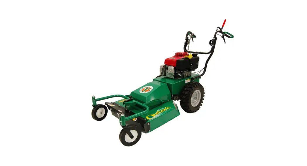
 BC26 HYDRO-DRIVE Operator’s Manual
BC2601HHC Hydro Series Brush Cutter
Operator’s Manual
Beginning Serial #: 122020001
Original Instructions
IMPORTANT- READ CAREFULLY BEFORE USE AND KEEP FOR FUTURE REFERENCE
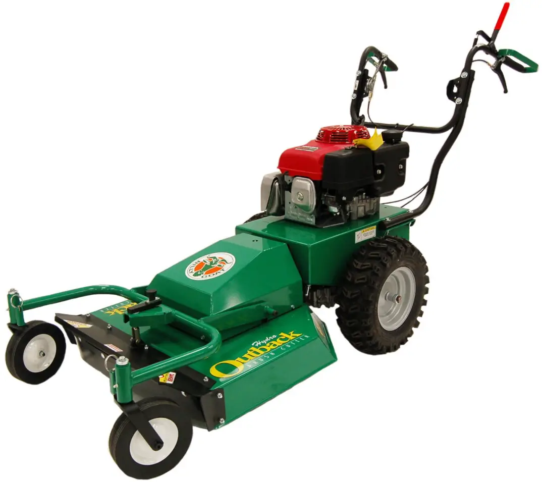
BC26 SERIES SPECIFICATIONS
| BC2601 HHC | |
| Engine Type | Honda GXV390 |
| Model Number | GXV39OUT1 DABG |
| Displacement | 390 cc |
| Fuel Capacity | 2.2 qt (2.1 L) |
| Oil Capacity | 1.2 qt (1.1L) |
| Unit Weight | 325 lb (147.4 kg) |
| Overall Length | 80 in (2.03 m) |
| Overall Width | 31 in (0.78 m) |
| Overall Height | 48 in (1.21 m) |
| Maximum Operating Slope | 20° |
INSTRUCTION LABELS
The labels shown below were installed on your BILLY GOAT ® Hydro-Drive Brush Cutter. If any labels are damaged or missing, replace them before operating this equipment. Item numbers from the Illustrated Parts List and part numbers are provided for convenience in ordering replacement labels. The correct position for each label may be determined by referring to the Figure and Item numbers shown.
 |  | ||
| PN 100261 (Item 61) | PN 100346 (Item 134) | PN 501502(Item 85) | PN 400424 (Item 5) |
 |  | 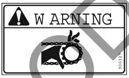 | 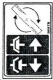 |
| PN 810736 (Item 136) | PN 501512 (Item 165) | PN 900327 (Item 20) | PN 500177 (Item 135) |
 |  | OPERATION OF THIS EQUIPMENT MAY CREATE SPARKS THAT CAN START FIRES AROUND DRY VEGETATION A SPARK ARRESTOR MAY BE REQUIRED. THE OPERATOR SHOULD CONTACT LOCAL FIRE AGENCIES FOR LAWS OR REGULATIONS RELATING TO FIRE PREVENTION REQUIREMENTS |
| PN 501504 (Item 139) | PN 500168 (Item 140) | PN 100256 (Item 62) |
 | WARNING HOT SURFACES DO NOT TOUCH HOT SURFACES DO NOT TOUCH |
ENGINE LABELS
WARNING GASOLINE IS FLAMMABLE SHUT OFF ENGINE, AVOID HEAT, SPARKS, AND OPEN FLAME WHEN REFUELING
Honda
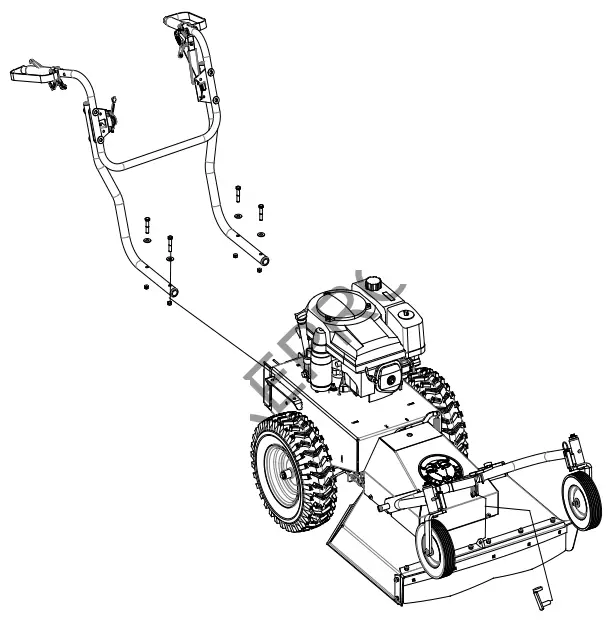
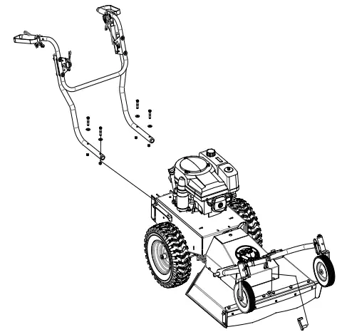
Brush Cutter Assembly Drawing
PACKING CHECKLIST
Your BILLY GOAT® BC Hydro-Drive Brush Cutter was shipped in one carton, completely assembled except for the upper handle assembly and the front caster bracket mount. Mounting hardware for the handle and caster bracket mount can be found in the parts bag. The throttle cable hardware is located on the bracket on the right side of the handle.
NOTE: A CB18, C50, SC50, or MCB50 series dry or wet battery with a 17.2 Ah rating is required when replacing the battery.![]() READ all safety instructions before assembling unit.
READ all safety instructions before assembling unit.![]() WARNING DISCONNECT spark plug wire before assembling unit.
WARNING DISCONNECT spark plug wire before assembling unit.
PARTS BAG & LITERATURE ASSY
Warranty card P/N- 80102772, Owner’s Manual P/N-501533, General Safety, and Warranty Manual P/N-100296, Declaration of conformity P/N-100502
Boxing Parts Checklist
- Owner’s Manual 501533
- Upper Handle Assembly, P/N 501010, Electric model P/N 501009
- Ty-Wraps (4 ea)
- Screwcap 3/8” – 16 X 2” P/N 8041054 (qty 4)
- Washer 3/8” flat P/N 8171004 (qty 4)
- Nut Lock 3/8”-16 P/N 8160003 (qty 4)
- Nut lock #10-24 hex P/N 8164005 (qty 2)
- Screw machine flat HD Phil P/N 830514 (qty 2)
- Spring pin clevis P/N 501318 (qty 1)
Engine Manual Per Model
- Honda
ASSEMBLY
NOTE: Items in ( ) can be referenced in the Parts Illustrations and Parts Lists on pages 14-21.
- REMOVE the unit from the carton and check the contents of the parts bag with the list above.
- REMOVE mounting hardware from the hardware bag.
- ATTACH the handle to the engine base with items 72, 73, and 48.
- TIGHTEN mounting hardware on handle braces (items 5 and 6).
- ATTACH the throttle (82) to the right-hand bracket (item 70) using hardware items 83 and 84. Tighten securely and make sure the cable isn’t binding.
- ATTACH the Blade drive cable to the lever and seat the plastic insert into the bracket on the left side of the handle.
- SECURE the drive and blade cables with the ty-wraps provided.
- ATTACH the caster bracket frame to the deck with the clip (item 164), make sure the clip section snaps completely around the neck of the yoke.
- RECONNECT spark plug wire.
OPERATION
OPERATOR CONTROLS
The operator’s station is at the rear of the machine between the handlebars. The operator should STAND in a position to allow both handlebars to be grasped firmly and which allows sufficient leverage to steer the machine. Operator’s controls are shown below.
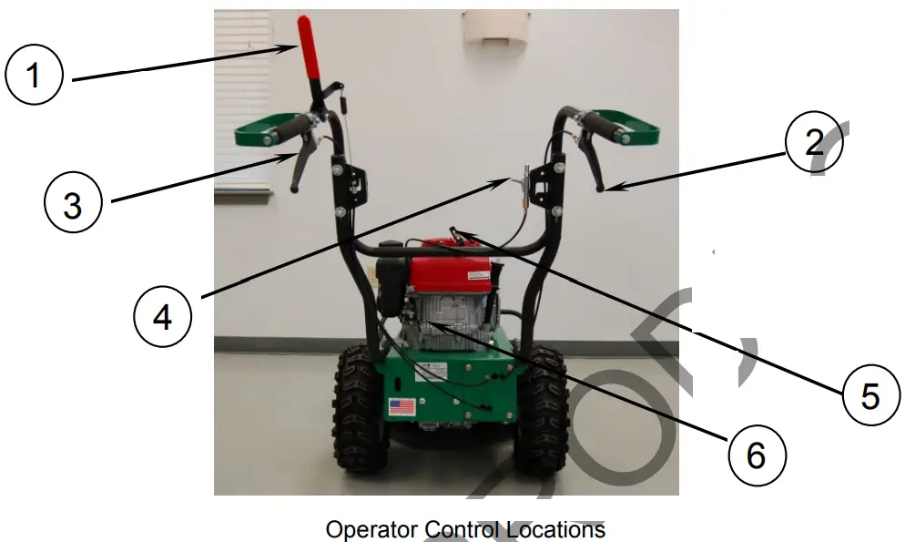
- Blade Clutch Lever
- Forward Lever
- Reverse Lever
- Throttle
- Pull Starter
- Choke
STARTING ENGINE![]() CHECK engine oil level before operating the machine.
CHECK engine oil level before operating the machine.![]() DO NOT START equipment with drive or blade clutch engaged.
DO NOT START equipment with drive or blade clutch engaged.
- Place equipment on a level, firm surface that is free of rocks or other debris.
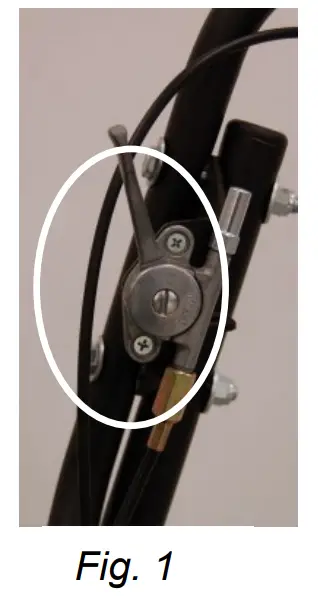
- Place the throttle in the “fast” position. (See Fig. 1)
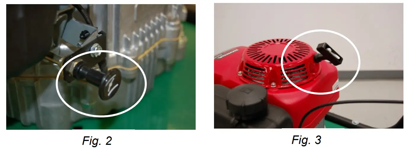
- Pull choke out (See Fig. 2 Honda engine only).
- Units equipped with manual starters: Pull the starter rope to start the engine. NOTE: PULL STARTER CORD slowly until resistance is felt. Then pull the cord rapidly to avoid kickback. (See Fig. 3)
- Push choke in (Honda engine only).
- Pull throttle control back to and allow the engine to reach the correct operating speed.
CUTTING OPERATION
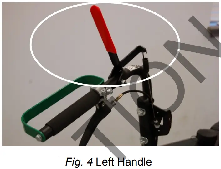
- Press the blade clutch handle down (See Fig. 4) to engage the blade. Allow the blade to spin up to normal operating speed.
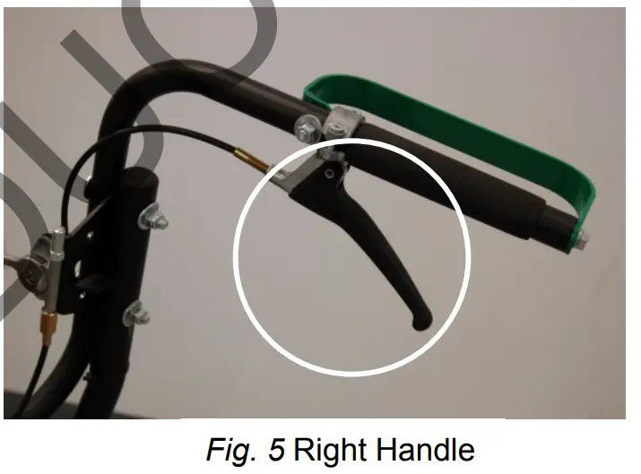
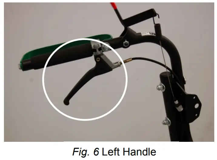
- Pull the Forward (See Fig. 5) or Reverse Drive lever (See Fig. 6) up to engage the transaxle in the desired direction.


DECK HEIGHT ADJUSTMENT
1. To raise and lower the cutting height on the deck, pull the knob upwards and rotate the handle clockwise to raise the cutting height and counterclockwise to lower the cutting
height. DO NOT ADJUST HEIGHT WITH THE BLADE RUNNING
CLEARING A CLOGGED DECK
DISCONNECT spark plug wire before servicing unit.![]() WARNING DISCONNECT spark plug wire before servicing unit.
WARNING DISCONNECT spark plug wire before servicing unit.
- Shut engine off and wait for blade to stop completely.
- Disconnect spark plug wire.
- Remove clog from cutting deck.
 WEAR durable gloves. Clog may contain sharp materials.
 - Reconnect spark plug wire.
SHUT DOWN
- Release the drive lever (Fig. 5/6) to disengage the transaxle.
- Release the blade clutch handle (Fig. 4) to disengage the blade.
- Move the throttle to the slowest possible position on the throttle control.
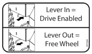
 NEUTRAL/FREEWHEEL
- Identify the freewheel lever located in front of the right front wheel when viewing from operator’s station.
- Pull the lever to initiate freewheel motion.
- Push the lever in to initiate driver-enabled motion.
*****TIPS*****
The best performance is achieved when cutting in dry conditions. The quality of the cut is directly related to ground speed during cutting. Under most conditions cutting should be done at a slower ground speed. Fast speeds should be reserved for conditions where weeds and brush are thinned out or not very tall. If the quality of the cut is not satisfactory, an attempt at slower speeds.
MAINTENANCE
PERIODIC MAINTENANCE
Periodic maintenance should be performed at the following intervals:
| Maintenance Operation | Every Use | Daily or Every 5 Hours | Every 25 Hours | Every 50 Hours | Every 100- 150 Hours |
| Inspect for worn or damaged parts | ● | ||||
| Check for excessive vibration | ● | ||||
| Inspect for loose parts | ● | ||||
| Sharpen blade. Note: nut will need to be replaced when the blade is removed | ● | ||||
| Inspect belts for wear | ● | ||||
| Lubricate throttle control cable and linkage | ● | ||||
| Check blade clutch cable tension | ● | ||||
| Inspect the battery for corrosion, damage, or leaks (electric start units only) | ● | ||||
| Apply anti-seize compound to rear axles | ● | ||||
| Check the battery strap for excessive wear or rips | ● | ||||
| Replace blade drive and transaxle drive belts | ● |
If the transmission is topped off or refilled, SAE 10w30 grade, non-detergent oil should be poured through the port covered by the black cap. Approx. 2.2 liters of oil will be needed to reach this level. This is dependent on the amount of residual oil remaining in case after draining. Draining of old oil must be done through the same port (covered with the black plug) by inverting the transaxle.
COMMON REPLACEMENT PARTS
- Blade. P/N 501221. Original equipment replacement blade.
- Transaxle Drive Belt. P/N 501268. Original equipment replacement drive belt.
- Blade Drive Belt. P/N 501220. Original equipment replacement drive belt.
- Throttle Control Assembly. Throttle control including cable.
CLEANING
Your BILLY GOAT® Brush Cutter should be cleaned periodically to ensure optimum performance and service life. Clogs and debris should be removed from the blade area and debris should be removed from the engine cooling fins. A garden hose or pressure washer may be used for cleaning.![]() CAUTION:
CAUTION: ![]() DO NOT SPRAY WATER DIRECTLY ON THE BLADE CLUTCH WHEN USING A POWER WASHER. SEE FIG 7.
DO NOT SPRAY WATER DIRECTLY ON THE BLADE CLUTCH WHEN USING A POWER WASHER. SEE FIG 7.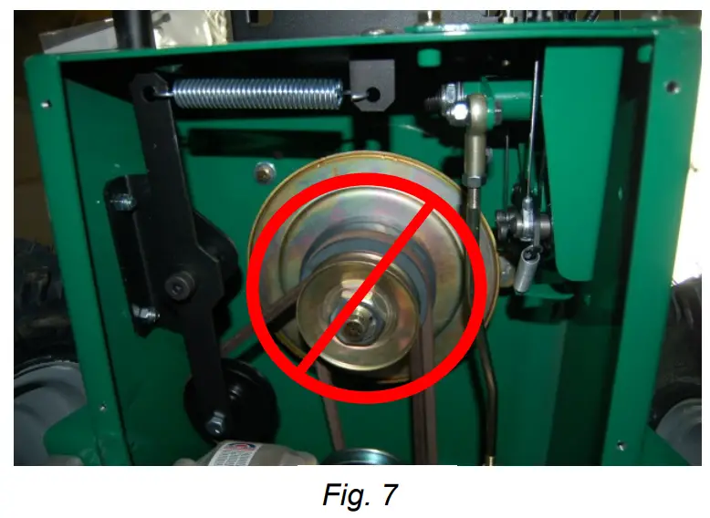 NOTE: Items in ( ) can be referenced in the Parts Illustrations and Parts Lists on pages 14-21.
BLADE SHARPENING AND REMOVAL![]() READ all safety instructions before servicing unit.
READ all safety instructions before servicing unit.![]() WARNING DISCONNECT spark plug wire before servicing unit.
WARNING DISCONNECT spark plug wire before servicing unit.
- Disconnect spark plug wire.
- Lift and support front of unit to allow access to underside.
UNIT IS HEAVY. Make sure support is adequate to support weight of machine. - Block the blade to prevent it from rotating during removal.
- Remove the blade bolt (item 23), and the friction washer (item 39).
- Remove the blade (item 2) and install a replacement blade. NOTE: When sharpening the blade make sure to sharpen all cutting edges. If the lock nut is removed and replaced more than once, it should be replaced with a new lock nut (P/N 8160009).
When replacing the blade use BILLY GOAT Industries PN 501224 only. - Attach a new blade with a new blade bolt (item 23), and a new friction washer (item 39) removed earlier and included with your new blade.
NOTE: Inspect fasteners for wear and replace if necessary. - Torque blade bolt to 40 ft-lbs.
- Reconnect spark plug wire.
BLADE DRIVE BELT TENSION
NOTE: The Blade Drive belt is under constant tension by the idler arm on the deck.![]() WARNING DISCONNECT spark plug wire before servicing unit.
WARNING DISCONNECT spark plug wire before servicing unit.
- Disconnect spark plug wire.
- Loosen four screws (item 27) holding the belt deck cover (item 29) and remove the cover.
- Examine condition of the belt and the amount of tension on the belt.
- If the idler is not providing enough tension inspect the spring (item 50) attaching it to the spindle base. If not enough tension is being put on the arm, replace the spring.
- Replace the engine base door (item 29) and secure it with the screws removed earlier.
- Reconnect spark plug wire.
- Check belt tension by operating the unit under conditions that caused belt slippage. If the belt continues to slip it may require replacement before the operation may continue.
BLADE CLUTCH ADJUSTMENT![]() WARNING DISCONNECT spark plug wire before servicing unit.
WARNING DISCONNECT spark plug wire before servicing unit.
- Disconnect spark plug wire.
- As the clutch/brake wears or begins slipping or squealing, an adjustment may be required to maintain proper cable tension and clutch engagement. A properly adjusted blade clutch should require 10 lbs. of force to depress the end of the clutch lever. The blade clutch cable spring should stretch 1/4” to 3/8” (6.4-9.5 mm).
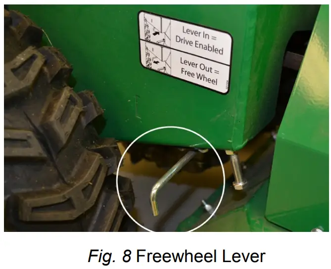
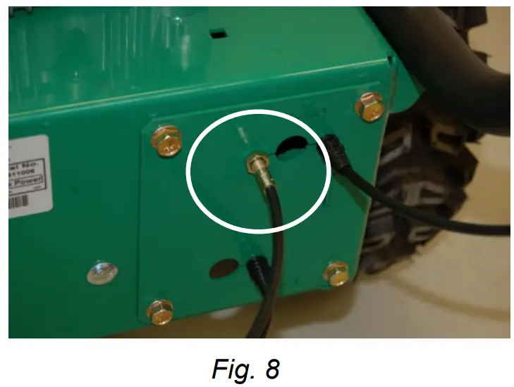
- Adjust cable tension by tightening or loosening the cable adjustment nut on the rear of the engine base (see Fig. 8). Be sure to leave enough slack in the cable to allow the blade brake to engage.
- Reconnect spark plug wire.
![]() CAUTION: If clutch continues to slip or squeal, do not operate the equipment until adequate adjustment or repair has been performed. Improper adjustment can cause the clutch to overheat and slip, greatly reducing performance and clutch life.
CAUTION: If clutch continues to slip or squeal, do not operate the equipment until adequate adjustment or repair has been performed. Improper adjustment can cause the clutch to overheat and slip, greatly reducing performance and clutch life.
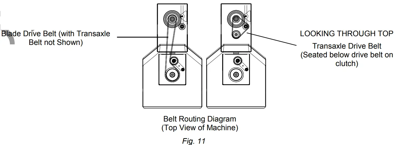
NOTE: See Fig 11 for proper belt routing.
TRANSAXLE DRIVE BELT REMOVAL AND REPLACEMENT![]() WARNING DISCONNECT spark plug wire before servicing unit.
WARNING DISCONNECT spark plug wire before servicing unit.
- Disconnect spark plug wire.
- Lift and support the rear of the unit to allow access to the underside.
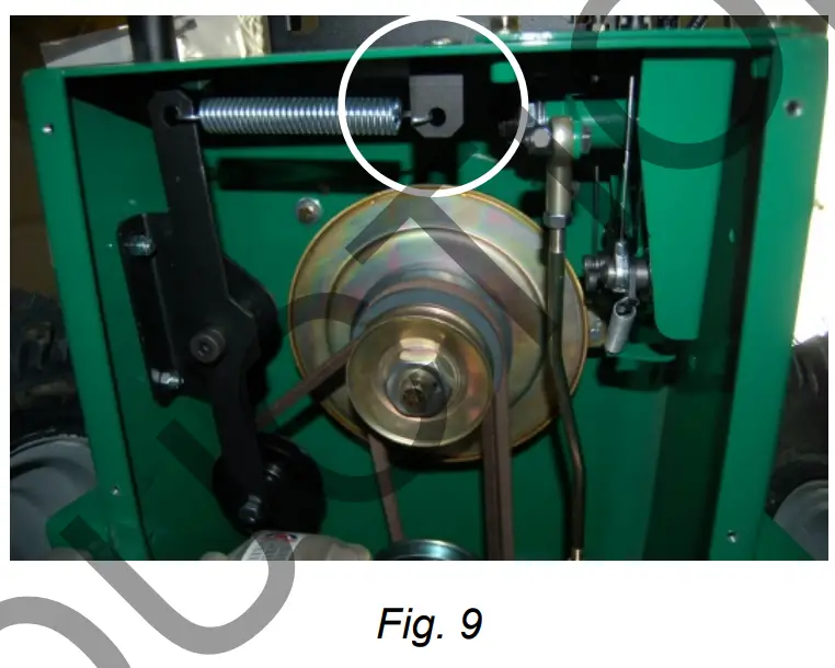
- Detach the spring (item 50) from the bracket (item 98) that is keeping tension on the drive belt. (See Fig. 9)
- Walk the belt (item 121) off of the clutch (item 54) by slowly pulling the engine over. WARNING: use caution not to pinch fingers between the belt and clutch.
- Slip the belt off of the transaxle pulley.
- Replace the belt in reverse order. NOTE: make sure the belt is seated properly in the clutch and transaxle and make sure that it does not bend over the fan blades on the transaxle.
BLADE DRIVE BELT REMOVAL AND REPLACEMENT![]() WARNING DISCONNECT spark plug wire before servicing unit.
WARNING DISCONNECT spark plug wire before servicing unit.
- Disconnect spark plug wire.
- Lift and support rear of unit to allow access to underside.
UNIT IS HEAVY. Make sure support is adequate to support weight of machine. - Loosen the four screws (item 27) holding the deck belt cover (item 29) and remove the cover.
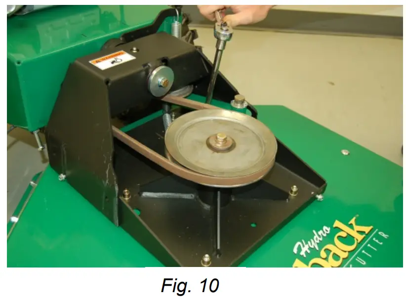
- Follow steps 3 and 4 in the Transaxle drive belt removal section to remove the Transaxle drive belt. NOTE: It may be necessary to pry idler pulley (item 35) away from its original position to release the belt, using a ratchet with an extension in the square hole on the idler arm should allow the proper leverage to pull it off the belt. (See Fig. 10)
- Relieve the tension on the blade belt by pulling the deck idler arm off of the belt. Then walk the belt off of the deck pulley.
- Feed the belt back to the engine base then slip the belt off of the clutch.
- Install the new belt in reverse order making sure the belt is seated properly in the clutch.


TRANSAXLE DRIVE ADJUSTMENT
![]() WARNING DISCONNECT spark plug wire before servicing unit.
WARNING DISCONNECT spark plug wire before servicing unit.
- Disconnect spark plug wire.
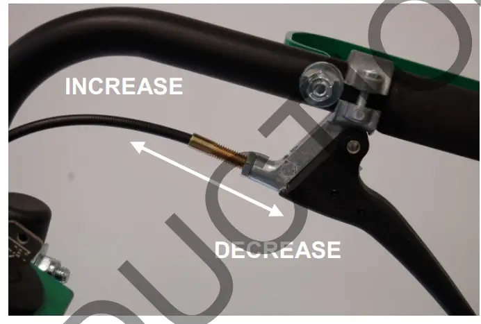
- Adjustments to cable tension are made at the barrel entering the Drive Control Levers.
- Adjust cable tension by tightening or loosening the cable adjustment barrel on the rear of the engine base (see below).
NOTE: Moving the cable adjustment barrel OUT increases tension. Moving the barrel IN decreases tension. Increasing the tension too much will cause the drive to stay engaged whereas not enough will cause it not to engage when the lever is pulled. - Reconnect spark plug wire.

TROUBLESHOOTING
| Problem | Possible Cause | Corrective Action |
| Engine will not start | Throttle is set to a Slow/Stop position. | Move the throttle to the fast position. |
| Out of gasoline. | Fill the gas tank. | |
| Old or contaminated gasoline. | Drain the gas tank and fill it with fresh gasoline. | |
| Spark plug wire disconnected. | Connect spark plug wire. | |
| Dirty air cleaner. | Clean or replace air cleaner. | |
| Will not cut or cutting performance is poor | Blade drive cable tension is incorrect. | Adjust blade drive cable tension. |
| Dull blade. | Sharpen or replace the blade. Note: nut will need to be replaced when the blade is removed. | |
| Clogged deck. | Unclog deck. | |
| Excessive debris built up on or blocked the blade. | Clear debris from the blade area. | |
| Engine RPM set too low. | Check engine RPM. | |
| Abnormal vibrations | Blade loose or out of balance. | Check the blade for tightness. Rebalance if necessary. |
| Engine loose. | Check engine mounting bolts. | |
| Blade drive belt is worn. | Replace the blade drive belt. | |
| Belt slips or smokes | Belt tension is too low. | Adjust belt tension. |
| Belt is worn or stretched. | Replace belt. | |
| Pulleys worn or damaged. | Replace pulleys. | |
| Clutch slips or squeals | Clutch cable tension is too low. | Replace the spring on the idler arm. |
| Clutch wore or damaged. | Replace worn or defective clutch assembly parts. | |
| Blade brake will not engage | Inadequate slack in the clutch cable. | Adjust the clutch cable. |
| Clutch wore or damaged. | Replace clutch/brake assembly. | |
| Transaxle will not engage | Clutch lever is not engaging the clutch. | Adjust the clutch cable. |
| Clutch cable is defective. | Replace cable. | |
| Belt is worn or broken. | Replace belt. | |
| Transaxle will not disengage | Clutch cable out of adjustment. | Adjust the clutch cable. |
| Engine will not turn over | Defective blade clutch. | Replace clutch. |
| Engine problem. | Contact an authorized servicing dealer for your engine. |
BC26 HYDRO-DRIVE DECK PARTS DRAWING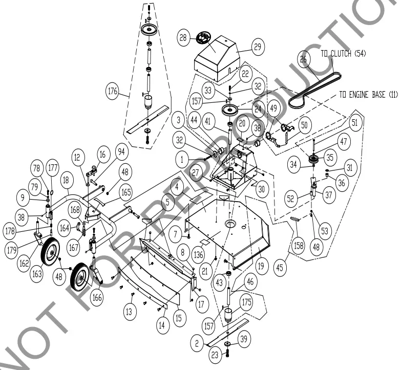
| ITEM NO | DESCRIPTION | BC2601HHC | |
| Part No | QTY | ||
| 1 | SCREWCAP 3/8-24 X 1” HCS GR. 8 | 900154 | 1 |
| 2 | BLADE 26” FLAT BC26 | 501224 | 1 |
| 3 | WASHER DECK RETAINNG | 501214 | 1 |
| 4 | LABEL BADGING BC26 HYDRO | 501500 | 1 |
| 5 | LABEL DANGER | 400424 | 4 |
| 7 | BOLT CARRIAGE 5/16”-18 X 3/4” ZP | 8024039 | 6 |
| 8 | NUT LOCK 5/16-18 ZP | 8160002 | 15 |
| 9 | WASHER 1.125” OD X 0.344” ID X .25” THK | 441150 | 2 |
| 12 | BUSHING FLANGED 1.250” X 0.380” ID | 501316 | 1 |
| 13 | CARRIAGE BOLT 5/16”-18 X 1” | 8024040 | 5 |
| 14 | PLATE FRONT DEFLECTOR | 501319 | 1 |
| 15 | RUBBER DEFLECTOR FRONT | 501320 | 1 |
| 16 | HEIGHT ADJUST HANDLE ASSY | 501124 | 1 |
| 17 | DECK INTAKE WA EURO BC26 | 501123 | 1 |
| 18 | CASTER FRAME WA | 501125 | 1 |
| 19 | DECK BC26EU WA W/LABELS | 501121-S | 1 |
| 20 | LABEL DANGER GUARD | 900327 | 1 |
| 21 | SCREW SER HEX WASHER FLNG | 791080 | 6 |
| 22 | SCREWCAP 3/8”-16 X 1 1/4” HCS ZP | 8041051 | 1 |
| 23 | SCREWCAP 9/16”-18 X 1 3/4” GR 8 | 501345 | 1 |
| 24 | PULLEY 7” OD X 1.000 BORE | 501308 | 1 |
| 26 | BELT 6972 POWERATED | 501220 | 1 |
| 27 | SCREW SELT TAP 1/4-20 X 5/8” HWH TYPE F | 890359 | 4 |
| 28 | LABEL PRODUCT DECAL LG CIRCLE | 430303 | 1 |
| 29 | COVER BELT DECK WA BC26 W/LABEL | 501602 | 1 |
| 30 | PIN COTTER 1/8” X 1” | 8197031 | 1 |
| 31 | WASHER .765 ID X 1.25 OD X .06 THK | 850238 | 1 |
| 32 | WASHER LOCK 3/8 S/T MED | 8177012 | 1 |
| 33 | WASHER 1.5 OD X .453 ID X .25 THK | 440153 | 1 |
| 34 | TUBE PIVOT IDLER VQ | 830526 | 1 |
| 35 | PULLEY IDLER 4.00 OD X 3/8” BORE | 500113 | 1 |
| 36 | BUSHING PIVOT FRAME AE | 360183 | 1 |
| 37 | ARM IDLER DECK WA BC | 501103 | 1 |
| 38 | ZERK FITTING GREASE | 610363 | 3 |
| 39 | WASHER BLADE BC26 | 501346 | 1 |
| 41 | SPACER SPINDLE BEARING BC26 | 501245 | 1 |
| 43 | BEARING, BALL 1641 – 2RS-PRX | 501302 | 2 |
| 44 | BUSHING 1.500 ID X 1.5 LONG FLANGED | 501217 | 2 |
| 45 | BRACKET DECK MOUNT WA BC26 W/LABEL | 501604 | 1 |
| 46 | SHAFT BLADE BC26 | 501341 | 1 |
| 47 | WASHER 3/8” SAE | 8172009 | 1 |
| 48 | NUT LOCK 3/8-16 HEX | 8160003 | 4 |
| 49 | ARM RTN WA BC26 | 501116 | 2 |
| 50 | SPRING LIFT ASSIST TENSION | 351254 | 2 |
| 51 | SCREWCAP 3/8”-16 X 3 3/4” HCS ZP | 8041061 | 1 |
| 52 | BUSHING PIVOT LIFT | 360138 | 1 |
| 53 | NUT LOCK 3/8”-16 LT WT TH ZP | 8161042 | 1 |
| 78 | SCREWCAP 5/16”-18 X 1” GR 5 HCS ZP | 8041028 | 2 |
| 79 | WASHER LOCK 5/16” S/T MED | 8177011 | 2 |
| 94 | BOLT SHOULDER 1/2” X 2” | 520031 | 2 |
| 136 | LABEL WARNING FLYING DEBRIS | 810736 | 1 |
| 157 | KEY 1/4 SQ. X 0.75” | 9201109 | 2 |
| 158 | SPRING IDLER BC | 501261 | 1 |
| 162 | CASTER RIGHT SIDE WA | 501126 | 2 |
| 163 | TIRE WHEEL ASSY | 501333 | 2 |
| 164 | SPRING PIN CLEVIS | 501318 | 1 |
| 165 | LABEL HEIGHT ADJUST EURO BC26 | 501512 | 1 |
| 166 | CASTER LEFT SIDE WA | 501127 | 1 |
| 167 | YOKE FEMALE STEEL 3/8”-24 RH X 2.50 | 501317 | 1 |
| 168 | NUT LOCK 3/8”-24 ZP THIN HT | 8161022 | 1 |
| 175 | ADAPTER BLADE WA BC26 | 501343 | 1 |
| 176 | BLADE PULLEY AND ADAPTER KIT SERVICE | 501611 | N/A |
| 177 | KEY, RING 1-5/8 OD | 501336 | 2 |
| 178 | SWIVEL LOCK SPRING | 501337 | 2 |
| 179 | 7/16” DIA SWIVEL LOCK PIN, PLT | 501335 | 2 |
| ITEM NO | DESCRIPTION | BC2601HHC | |
| Part No | QTY | ||
| 1 | SCREWCAP 3/8-24 X 1” HCS GR. 8 | 900154 | 1 |
| 3 | WASHER DECK RETAINING | 501214 | 1 |
| 8 | NUT LOCK 5/16”-18 ZP | 8160002 | 2 |
| 11 | ENGINE BASE WA W/LABELS | 501603 | 1 |
| 27 | SCREW SELT TAP 1/4-20 X 5/8” HWH TYPE F | 890359 | 4 |
| 32 | WASHER LOCK 3/8” S/T MED | 8177012 | 1 |
| 54 | CLUTCH | 501223-S | 1 |
| 55 | WASHER LOCK S/T MED | 8177013 | 1 |
| 56 | SCREWCAP 7/16”-20 X 3 1/2” GR 8 W/PATCH | 440150 | 1 |
| 58 | ENGINE 13 HP HONDA PULL GXV390UT1 DAXB | 501361 | 1 |
| 59 | SCREWCAP 5/16”-18 X 1 3/4 HCS ZP | 8041031 | 2 |
| 60 | WASHER 5/16” FLAT | 8171003 | 4 |
| 61 | LABEL WARNING FUEL | 100261 | 1 |
| 62 | LABEL SPARK ARRESTOR | 100256 | 1 |
| 63 | PLATE CHOKE BC26 | 500325 | 1 |
| 64 | SCREWCAP 5/16-24 X 1” GR 8 ZP W/PATCH | 400164 | 2 |
| 65 | SCREWCAP 5/16”-18 X 2” HCS ZP | 8041032 | 2 |
| 66 | NUT FLANGE 5/16”-18 ZP | 350346 | 4 |
| 67 | SCREW SER HEX WSHR FLNG 5/16-18 X 3/4” | 351264 | 4 |
| 68 | GUARD REAR HYDRO BC26 | 501295 | 1 |
| 80 | CABLE CLUTCH | 501279 | 1 |
| 132 | LABEL MADE IN USA | 520116 | 1 |
| 134 | LABEL SAFETY PROTECT READ MANUAL | 100346 | 1 |
| 159 | PIN CLEVIS 0.25 X 0.050 | 440124 | 1 |
| 160 | PIN, RUE RING 0.250″ | 371275 | 1 |
| ITEM NO | DESCRIPTION | BC2601HHC | |
| Part No | QTY | ||
| 8 | NUT LOCK 5/16-18 ZP | 8160002 | 3 |
| 48 | NUT LOCK 3/8-16 HEX | 8160003 | 8 |
| 69 | HANDLE LOWER LEFT | 501400 | 1 |
| 70 | BRACKET THROTTLE BC26 | 501251 | 2 |
| 72 | SCREWCAP 3/8”-16 X 2” | 8041054 | 4 |
| 73 | WASHER 3/8” FLAT | 8171004 | 12 |
| 74 | BOLT SHOULDER 3/8”-16 X 1 1/2” | 501313 | 1 |
| 75 | SCREWCAP 3/8”-16 X 3” HCS ZP | 8041058 | 4 |
| 76 | WASHER 1/4” FLAT | 8171002 | 2 |
| 77 | BOLT CARRIAGE 5/16”-18 X 1 1/2” ZP | 8024042 | 2 |
| 78 | SCREWCAP 5/16”-18 X 1” ZP | 8041028 | 2 |
| 79 | WASHER LOCK 5/16” S/T MED | 8177011 | 2 |
| 80 | CABLE CLUTCH | 501279 | 1 |
| 81 | LEVER CONTROL BLADE | 500312 | 1 |
| 82 | CONTROL THROTTLE | 440013 | 1 |
| 83 | NUT LOCK LT #10-24 HEX | 8164005 | 2 |
| 84 | SCREW MACHINE FLAT HD PHIL #10-24 | 830514 | 2 |
| 85 | LABEL DRIVE DIRECTION | 501502 | 1 |
| 86 | PLUG TUBE INSERT 1.25” OD | 791056 | 4 |
| 87 | GRIP HANDLE | 500267 | 2 |
| 88 | GUARD HAND BC26 | 501215 | 2 |
| 89 | CONTROL MAGURA | 351209 | 2 |
| 90 | GRIP LEVER 0.125” X 1” X 5” RED | 500379 | 1 |
| 91 | HANDLE UPPER | 501402-S | 1 |
| 92 | HANDLE LOWER RIGHT | 501401 | 1 |
| 107 | CABLE SPEED CONTROL RT SERVICE | 501276-S | 1 |
| 130 | CABLE SPEED CONTROL LFT SERVICE | 351271-S | 1 |
| 135 | LABEL BLADE ENGAGE | 500177 | 1 |
| LABEL THROTTLE PULL START BC | 501314 | 1 | |
| 138 | CABLE THROTTLE | 440014 | 1 |
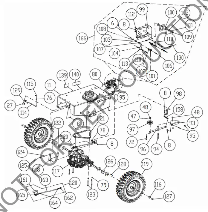
| ITEM NO | DESCRIPTION | BC2601HHC | |
| Part No | QTY | ||
| 6 | NUT LOCK 1/4”-20 HEX ZP | 8160001 | 2 |
| 8 | NUT LOCK 5/16”-18 | 8160002 | 8 |
| 11 | ENGINE BASE WA W/LABELS | 501603 | 1 |
| 27 | SCREW SELT TAP 1/4-20 X 5/8” HWH TYPE F | 890359 | 2 |
| 47 | WASHER 3/8” SAE | 8172009 | 1 |
| 48 | NUT LOCK 3/8”-16 HEX | 8160003 | 2 |
| 72 | SCREWCAP 3/8”-16 X 2” HCS ZP | 8041054 | 1 |
| 76 | WASHER 1/4” SAE | 8172007 | 1 |
| 78 | SCREWCAP 5/16”-18 X 1” HCS ZP | 8041028 | 1 |
| 79 | WASHER LOCK 5/16” S/T MED | 8177011 | 4 |
| 80 | CABLE CLUTCH | 501279 | 1 |
| 93 | BRACKET IDLER ARM HYDRO BC26 | 501269 | 1 |
| 94 | BOLT SHOULDER 1/2” X 2” | 520031 | 1 |
| 95 | BOLT CARRIAGE 5/16”-18 X 3/4” PLAIN | 9024039 | 4 |
| 96 | ARM IDLER DRIVE HYDRO BC26 WA | 501112 | 1 |
| 97 | PULLEY INSIDE IDLER BC26 | 501216 | 1 |
| 98 | BRACKET SPRING IDLER | 501297 | 1 |
| 99 | BRACKET, SPEED CONTROL WA | 373113 | 1 |
| 100 | WA, SPEED CONTROL CAM, LEFT | 351129 | 1 |
| 101 | BEARING 1/2” ID X 1.125” OD | 351257 | 2 |
| 102 | SPACER STEPPED SPEED CONTROL HYDRO DR | 351347 | 2 |
| 103 | SPACER EYELET SPEED CONTROL | 351348 | 2 |
| 104 | BUSHING 3/8” ID 1/2” OD X 3/8” LONG | 840078 | 4 |
| 105 | BUSHING, .500″ I.D. | 362254 | 2 |
| 106 | SCREWCAP 1/4-20 X 1 3/4 SKT BUT HD | 840199 | 2 |
| 107 | CABLE SPEED CONTROL RT SERVICE | 501276-S | 1 |
| 108 | WASHER 1/4” SAE | 8172007 | 2 |
| 109 | NUT-HEX-NYLK, FLG .375″-16 ZP | 8165003 | 1 |
| 110 | BOLT SHOULDER 3/8” X 1 3/4” | 351258 | 2 |
| 113 | BELLCRANK SPEED CONTROL BC26 | 501114 | 2 |
| 114 | ROD TRANS BYPASS BC26 | 501265 | 1 |
| 115 | HAIR PIN COTTER 1/4” | 900471 | 1 |
| 116 | WASHER .765 ID X 1.25” OD X .06 | 850238 | 2 |
| 117 | TRANSAXLE TUFF TORQ BC26 | 501218 | 1 |
| 118 | BRACKET SUPPORT HYDRO TRANSAXLE | 501267 | 1 |
| 119 | TIRE 16” AG SP | 501275 | 2 |
| 120 | CONTROL ROD ASSY | 501025-S | 1 |
| 121 | BELT HYDRO TRANSAXLE BC26 | 501268 | 1 |
| 122 | SCREW SELF TAP 5/16” X 3/4” HEX | 8123128 | 1 |
| 123 | SCREWCAP 5/16”-18 X 2 3/4” HCS ZP | 8041035 | 4 |
| 124 | WASHER 5/16” SAE | 8172008 | 1 |
| 125 | SCREWCAP 5/16”-18 X 3/4” HCS ZP | 8041026 | 1 |
| 126 | WASHER 3/4” SAE | 8172015 | 6 |
| 127 | RING RETAINING E 3/4” | 850230 | 2 |
| 128 | KEY 3/16” SQ X 2 1/8” | 9201087 | 2 |
| 129 | BRACKET BYPASS ROD | 501272 | 1 |
| 130 | CABLE SPEED CONTROL LFT SERVICE | 351271-S | 1 |
| 139 | LABEL DRIVE RELEASE | 501504 | 1 |
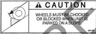
| 140 | LABEL CHOCK WHEELS | 500168 | 2 |
| 158 | SPRING IDLER BC | 501261 | 1 |
| 169 | SPRING PIN CONTROL ROD | 501262 | 1 |
| 170 | SPHERICAL ROD END MSF-5 | 351278 | 1 |
| 171 | CONTROL ROD | 501260 | 1 |
| 172 | NUT JAM 5/16” NC | 8143002 | 2 |
| 173 | YOKE FEMALE STEEL 5/16” – 24 RH X 2.25” | 501274 | 1 |
| 174 | KIT SPEED CONTROL NO CABLES BC26 | 501607 | 1 |
Part No 501533
501533_B_HI


-mp1220 72 Inch Brush Cutter Instruction Manual")


