Kentec Taktis Fire Alarm Control Panel User Guide
What’s in the box?
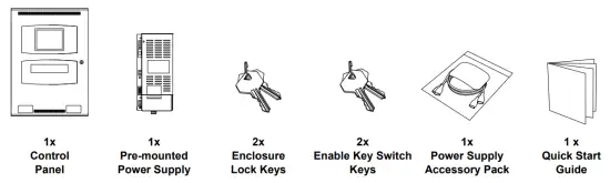
The Taktis FACP includes the following components and hardware.
Figure A-1
Items in the box (NOT TO SCALE)
QR Code
The QR codes below provide links to the Taktis FACP Installation and Operation Manuals. Using your Smartphone, tablet or device install a third party QR Code Reader and scan the code to open the documents.
Figure A-2
Reading the QR Codes


Installation Manual
Operation Manual
Should you be unable to work with QR codes Manuals can be obtained by visiting the following website pages:
| Manual Variant | Website |
| Installation Manual | http://www.kentec.co.uk/manuals/man-1154GEN.pdf |
| Operation Manual | http://www.kentec.co.uk/manuals/man-1169GEN.pdf |
Panel at a Glance
The diagrams below provide an overview of the panel main components and features:
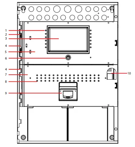
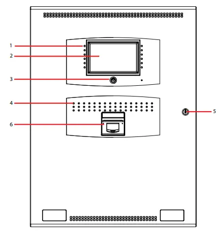
Figure A-3
2 to 8 Loop Panel Internal Layout
| ID | Description | Comment | ID | Description | Comment |
| 1 | Panel Indicators | Refer to Installation Manual for details. | 6 | Enable Keyswitch | Refer to Installation & Operation Manuals for details. |
| 2 | Hinge Pin | Refer to Installation Manual for details. | 7 | Lower Panel Fascia | Refer to Installation Manual for details. |
| 3 | Touch Panel Display | Refer to Installation & Operation Manuals for details. | 8 | Zone Indicators | Up to 144 Zone Indicators. Refer to Installation Manual for details. |
| 4 | Hinge Loops | Refer to Installation Manual for details. | 9 | Printer (Optional) | Refer to Installation Manual for details. |
| 5 | Upper Panel Fascia | Refer to Installation Manual for details. | 10 | Panel Lock Clearance | – |
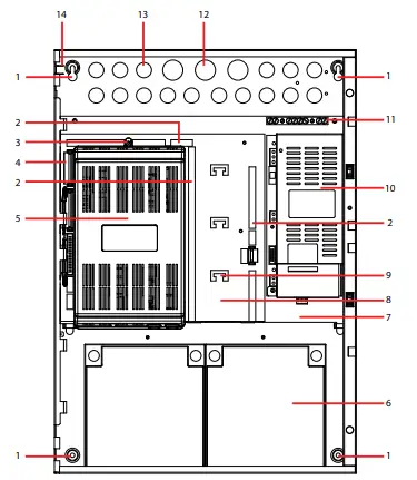
Figure A-4
2 to 8 Loop Panel Chassis Layout
| ID | Description | Comment | ID | Description | Comment |
| 1 | Enclosure Fixing Hole | Use 5mm bolts/screw fixings. Refer to fixing the cabinet in installation section for details. | 8 | Main Board | Refer to Installation Manual for details. |
| 2 | Field Terminals | Refer to Installation Manual for details. | 9 | Cable Tie Point | Refer to Installation Manual for details. |
| 3 | PCB Cover fixing | Refer to Installation Manual for details. | 10 | Power Supply | Power supply varies depending on version.5.25A shown. |
| 4 | Ribbon Cable Header | Refer to Installation Manual for details. | 11 | Earth Terminals | For field wiring. |
| 5 | PCB Cover | Refer to Installation Manual for details. | 12 | Knock-out 28mm dia. | Refer to Installation Manual for details. |
| 6 | Battery | Refer to Appendix section to determine battery type. | 13 | Knock-out 21mm dia. | Refer to Installation Manual for details. |
| 7 | Main Chassis | Refer to Installation Manual for details. | 14 | Earth Link | For continuity only. Refer to Installation Manual for details. |
Figure A-5
2 to 8 Loop Panel Rear of Door
| ID | Description | Comment | ID | Description | Comment |
| 1 | Hinge Loops | Refer to Installation Manual for details. | 4 | Lower Opening | – |
| 2 | Earth Link | For continuity only. Refer to Installation Manual for details. | 5 | Product Label/Logo Position | – |
| 3 | Upper Opening | – | 6 | Panel lock | – |
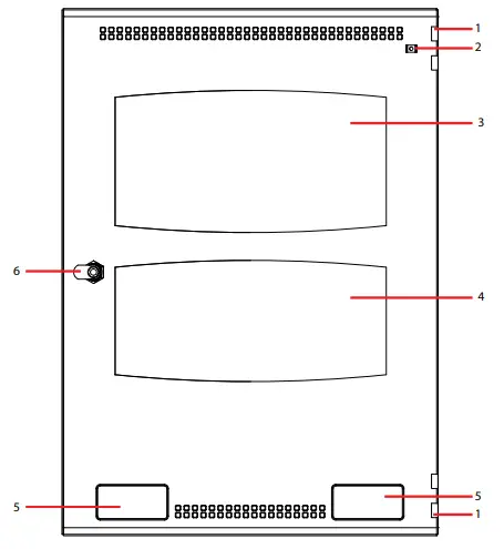
Figure A-6
2 to 16 Loop Front Panel Layout
| ID | Description | Comment | ID | Description | Comment |
| 1 | Panel Indicators | Refer to Installation Manual for details. | 4 | Zone Indications | Up to 144 Zone Indications. Refer to Installation Manual for details. |
| 2 | Touch Panel Display | Refer to Installation and Operation Manuals for details. | 5 | Panel Lock | – |
| 3 | Enable Keyswitch | Refer to Operation Manual for details. | 6 | Printer (Optional) | Refer to Installation Manual for details. |
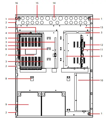
Figure A-7
2 to 16 Loop Panel Internal Layout
| ID | Description | Comment | ID | Description | Comment |
| 1 | Enclosure fixing hole | Use 5mm bolts/screws fixings. Refer to fixing the cabinet in installation section for details. | 9 | Battery | Refer to Installation manual for details. |
| 2 | Hinge Loop | Refer to Installation Manual for details. | 10 | Power Supply | Power supply varies depending on version.10.25A shown. |
| 3 | Field Terminals | Refer to Installation Manual for details. | 11 | Example Board | Refer to Installation Manual for details. |
| 4 | PCB Cover Fixing | Refer to Installation Manual for details. | 12 | Board Slot | Refer to Installation Manual for details. |
| 5 | Ribbon Cable Header | Refer to Installation Manual for details. | 13 | Main Chassis | Refer to Installation Manual for details. |
| 6 | Cable Tie Point | Refer to Installation Manual for details. | 14 | Knock-out 28mm dia. | Refer to Installation Manual for details. |
| 7 | Main Board | Refer to Installation Manual for details. | 15 | Knock-out 21mm dia. | Refer to Installation Manual for details. |
| 8 | Chassis Locating Lug | Refer to Installation Manual for details. | 16 | Earth Link | For continuity only. Refer to Installation Manual for details. |
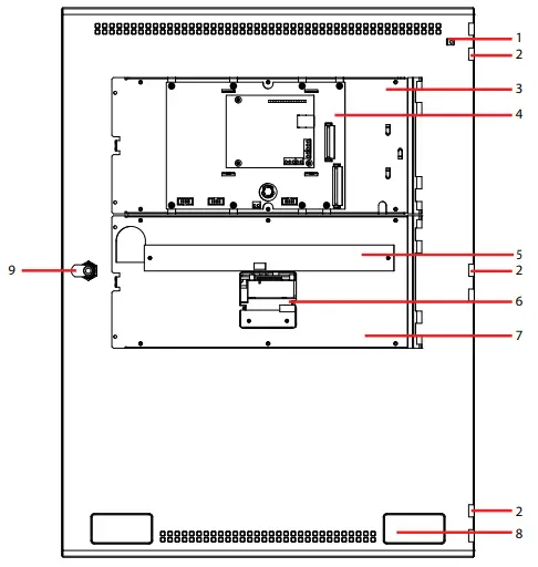
Figure A-8
2 to 16 Loop Panel Rear of Door
| ID | Description | Comment | ID | Description | Comment |
| 1 | Earth Link | For continuity only. Refer to Installation Manual for details. | 6 | Printer (Optional) | Refer to Installation Manual for details. |
| 2 | Hinge Loop | Refer to Installation Manual for details. | 7 | Door Chassis | Refer to Installation Manual for details. |
| 3 | Door Chassis | Refer to Installation Manual for details. | 8 | Product Label/Logo Position | – |
| 4 | LCD Main Processor Board | Refer to Installation Manual for details. | 9 | Panel Lock | – |
| 5 | Zone LED Board | Refer to Installation Manual for details. |
Hanging the Enclosure
To hang the enclosure proceed with the following steps.
For details on how to remove the enclose components please refer to the Installation Section of the FACP Installation Manual.
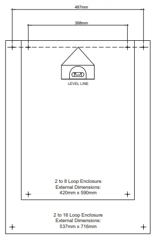
- Start by marking the fixing centres for the upper two enclosure fixing points. Ensure your fixing centres are level.
Figure A-9
Marking the enclosure fixing centres
Note: Where permissible use the appropriate wall plugs for your fixings. - Attach the two fixings to the wall using appropriate wall plugs. Screw fixings half-way home
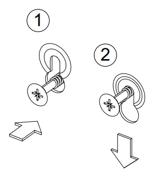
- Hang the enclosure on the two fixings, through the enclosure key-way fixing points.
Figure A-10
Hanging the enclosure on the key-way fixing points
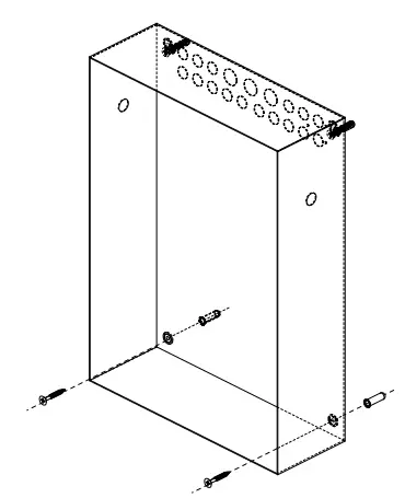
- With the enclosure in place, mark for the two lower fixings and attach as appropriate. Depending on fixing/wall type, you may need to temporarily remove the enclosure when making the lower fixing holes.
Figure A-11
Fixing the enclosure to the wall
- With the enclose in place, tighten all four fixings using appropriate force.
Compliance|
Taktis FACP’s are compliant with EN54-2, EN54-4 and are available with 2 to 8 loop or 2 to 16 loop, in four standard enclosure sizes.
The modular construction allows control panels to be configured with a range of options including, zonal fire indicators, a printer, additional supervised ancillary inputs and outputs, networking Taktis FACP’s together for larger system applications and remote communications.
A large format, touch screen display is used to provide an exceptionally clear and intuitive user interface. This product should be installed, commissioned and maintained by trained service personnel in accordance with the following:
- Regulations for electrical equipment in buildings specific to the country of use
- Codes of practice
- Statutory requirements
- Any instructions specifically advised by the manufacturer
- Only fire rated and shielded cable should be used.
Note: For LPCB approved installations use only FP200*, 1.5mm2 2 core cable.
Environmental Considerations
The PSU’s are mounted in steel enclosures within the CIE with an ingress protection rating of IP30. The operating temperature range should not exceed -5°C to +40°C (±2°C). Humidity levels should not exceed 95% (non-condensing).
Standards and Directives
The control equipment is designed in compliance for:
Table 1: Standards and Directives
| Low Voltage Directive 2014/35/EU | EMC Directive 2014/30/EU |
| EN62368 Audio/Video, Information and Communication Technology Equipment, Safety Requirements | EN50130 Electromagnetic compatibility – product family standard |
| EN54-2 | EN54-4 |
| EN54-13 |
Declaration Of Performance
Taktis fire alarm control and indicating equipment and power supply equipment conform to the essential requirements of the Construction Products Regulation No.305/2011
Table 2: Certified with the following Options with requirements from EN 54-2:1997
| 7.8 Output to fire alarm device(s) | 7.13 Alarm counter |
| 7.9.1 Output to fire alarm routing equipment | 8.3 Fault signals from points |
| 7.9.2 Alarm confirmation input from fire alarm routing equipment | 8.9 Output to fault warning routing equipment |
| 7.10.3 Output to type C | 9.5 Disablement of addressable points |
| 7.10.4 Fault monitoring of fire protection equipment | 10 Test condition |
| 7.11 Delay to outputs | |
| 7.12.1 Dependencies on more than one alarm signal – Type A | |
| 7.12.2 Dependencies on more than one alarm signal – Type B | |
| 7.12.3 Dependencies on more than one alarm signal – Type C |
Table 3: EN54-4: 1997 +A1:2002 +A2:2006 (Functions Provided)
| Operation from a main power supply- EN54-4 clause 5.1 | Operation from a standby battery – EN54-4 clause 5.2 |
| Monitor and charge the standby battery – EN54-4 clause 5.3 | Recognise and notify supply faults – EN54-4 clause 5.4 |
| S408 10.25A Universal Input Power Supply has been approved with 230V AC mains input. | S406 5.25A Power Supply has been approved both with 230V AC and 115V AC mains input. |
Table 4: Requirements subject to third party testing and approvals
IFAM German Interface Functionality
The products also comply with the following:
Table 5: Low Voltage and Electromagnetic Compatibility Directives
| Low Voltage Directive 2014/35/EU | Electromagnetic Compatibility Directive 2014/30/EU |
| EN62368 – Audio/Video, Information and Communication Technology Equipment Safety Requirements | BS EN55022: 1998 – Emissions, Spur. |
| EN50130-4: 1995 +A1:1998 +A2:2003 EN50130-4: 2011 Alarm systems, Electromagnetic compatibility – Product family standard: Immunity requirements for components of fire, intruder, hold up, CCTV, access control and social alarm systems. | |
| EN6100-6-3:2007:+A1:2001 – Electromagnetic compatibility (EMC) – Part 6-3: Generic standards – Emission standard for residential, commercial and light-industrial environments. |
Table 6: Additional functions provided that are not covered by EN54-2, EN54-4 or EN54-13
| Auxiliary power outputs | Programmable relay outputs |
| Programmable inputs | Programmable cause and effects |
| Ethernet and GPRS remote connections | Panel mounted printer |
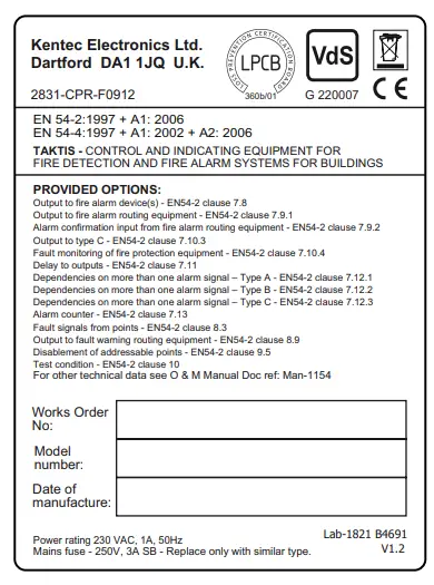
Rating Label
Safety
Suppliers of articles for use at work are required under section 6 of the Health and Safety at Work act 1974 to ensure as reasonably as is practical that the article will be safe and without risk to health when properly used. An article is not regarded as properly used if it is used without regard to any relevant information or advice relating to its use made available by the supplier. This product should be installed, commissioned and maintained by trained service personnel in accordance with the following
- IEE regulations for electrical equipment in buildings
- Codes of practice
- Statutory requirements
- Any instructions specifically advised by the manufacturer
According to the provisions of the Act you are therefore requested to take such steps as are necessary to ensure that you make any appropriate information about this product available to anyone concerned with its use This equipment is designed to operate from 230V 50Hz mains supplies and is of class 1 construction. As such it must be connected to a protective earthing conductor in the fixed wiring of the installation. A readily accessible double pole disconnect device with a disconnect air gap of at least 3mm and conforming to EN 60950, shall be incorporated in the fixed wiring. Failure to ensure that all conductive accessible parts of this equipment are adequately bonded to the protective earth will render the equipment unsafe.
Terms and Conditions
Details of Kentec Electronics Ltd. Terms and Conditions including Warranties and Returns & Repair Policies can be found on our website at the following locations:
Terms, Conditions & Warranty https://kentec.co.uk/terms-and-conditions/
Returns & Repairs https://kentec.co.uk/returns-policy/
Address of Kentec Electronics Ltd.
Units 25-26 Fawkes Avenue,
Questor, Dartford,
Kent. DA1 1JQ
United Kingdom
Registered in England:FACP
No.1937570
Tel: +44 (0)1322 222121
Disclaimer
In no event shall The Manufacturer be liable for any damages or injury of any nature or kind, no matter how caused, that arise from the use of the equipment referred to in this manual. Strict compliance with the safety procedures set out and referred to in this manual, and extreme care in the handling or use of the equipment, are essential to avoid or minimise the chance of personal injury or damage to the equipment. The information, figures, illustrations, tables, specifications, and schematics contained in this manual are believed to be correct and accurate as at the date of publication or revision. However, no representation or warranty with respect to such correctness or accuracy is given or implied and The Manufacturer will not, under any circumstances, be liable to any person or corporation for any loss or damages incurred in connection with the use of this manual.
The information, figures, illustrations, tables, specifications, and schematics contained in this manual are subject to change without notice. Unauthorised modifications to the fire detection system or its installation are not permitted, as these may give rise to unacceptable health and safety hazards. By installing this equipment on a computer network, the owner accepts full and unequivocal responsibility for ensuring that it is protected against all cyber threats and illegal tampering during the lifetime of the equipment. Any software forming part of this equipment should be used only for the purposes for which The Company supplied it. The user shall undertake no changes, modifications, conversions, translations into another computer language, or copies (except for a necessary backup copy). In no event shall The Manufacturer be liable for any equipment malfunction or damages whatsoever, including (without limitation) incidental, direct, indirect, special, and consequential damages, damages for loss of business profits, business interruption, loss of business information, or other pecuniary loss, resulting from any violation of the above prohibitions.


