
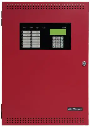
Mircom FX-3318 Single Loop Intelligent Fire Alarm Control Panel
Description
Mircom’s FX-3318 Addressable Fire Alarm Control Panel is an intelligent addressable multi-zoned panel with exceptional value while not compromising the Mircom features needed to satisfy small to medium jobs.
The FX-3318 is shipped pre-assembled with all main components including: main board, power supply, transformer, and main display in a red enclosure.
A built-in dialer is included to communicate panel status to the remote central monitoring station using 2 dedicated phone lines. Both SIA and Contact ID are supported
Up to 7 annunciators can be added with enclosure options in red, white or NEW stainless steel.
It has one built in signaling line circuit (SLC). With Mircom’s Advanced Protocol (AP) a superior group polling method as well as an interrupt feature, allows a faster response to an alarm. The AP or Advanced Protocol allows for greater system capacity with support for up to 318 devices in AP mode and offers legacy CLIP support of up to 198 devices.
FX-3318 has four Power Limited Class B (Style Y) or Class A (Style Z) NAC circuits.
NAC circuits may be configured as silenceable signal, non-silenceable signal, silenceable strobes, non-silenceable strobes, or relay output. The audible signal may be Steady, Temporal Code, California Code, or March Time.Sync strobe protocols are supported from major manufacturers.
The built-in trim ring accommodates both retrofits and new installs reducing time with semi-flush or surface mountable options.
The panel is UL, 9th edition listed and has COA and CSFM listings.
Features
- One onboard SLC communication circuit
- Supports up to 318 intelligent devices in AP mode
- Legacy Clip support of up to 198 devices
- Built-in Dialer Module for remote monitoring
- 4 x 20 LCD with 80 characters
- Supports up to 7 annunciators
- Optional City Tie/Polarity Reversal module for central station monitoring & field installable
- Four Power Limited Class B (Style Y) or Class A (Style Z) NAC circuits (max 1.5 Amps each – 5.0 amps total).
- Auxiliary power is available in the form of 24V FWR unfiltered and unsupervised, 24VDC filtered and regulated, and resettable auxiliary power supply.
- Positive Alarm Sequence (PAS)- provides an alarm delay of up to 180 seconds if an alarm is acknowledge at the control panel within 15 seconds. This action provides the responding personnel time to investigate an alarm before evacuating a building.
- Supports sync strobe protocols from major manufacturers.
- Two-stage, alarm verification, waterflow retard and positive alarm sequence operations.
- Configurable Signal Silence Inhibit, Auto Signal Silence, and One-Man Walk Test.
User Interfaces
Indication and Controls:
- 12 control buttons with associated LEDs
- 16 button Numeric Keypad with cursor buttons
LCD Display:
The display is a four line, 4 x 20 80 character back-lit alphanumeric LCD.
It displays information regarding the panel, its circuits, and devices. Report information provided by the LCD display includes:
- Alarm Log
- Event Log
- Current Levels
- Device Information
- Verification and Maintenance Reports
BATTERIES:
BAT-12V12A (12 AH) and BAT-12V18A (18 AH) will fit into the FX-3318 enclosure. To house BAT-12V26A (26 AH) batteries a BC-160/R Battery Cabinet is required. Use of alternative batteries may result in failure of the panel to meet agency and regulatory requirements and may result in shortened battery life. Batteries should be tested regularly and replaced at least every three years.
ADVANCED PROTOCOL AND CLIP DEVICES
- Maximum Loop Current = 350mA
- Maximum Loop Resistance = 40 ohms
- Maximum Loop Capacitance = 0.5uF
- Maximum number of isolators = 20
Agency Listings and Approvals:
UL-864 Rev 9, NFPA 70, 72, CSFM and COA
Compatible Receivers
The FX-3318 is compatible with the following Digital Alarm Communicator Receivers:
| DACR Receiver | Model Protocols |
| SurGard MLR2 Multi-Line Receiver (ULI approved) | SIA Format Protocol and SIA Contact ID |
| SurGard SLR Single-Line Receiver (ULI approved) | SIA Format Protocol and SIA Contact ID |
| Osborne-Hoffman Quickalert! II Receiver (ULI approved) | SIA Format Protocol and SIA Contact ID |
| Osborne-Hoffman OH-2000 Receiver (ULI approved) | SIA Format Protocol and SIA Contact ID |
| Silent Knight Model 9500 Receiver (ULI approved) | SIA Format Protocol and SIA Contact ID |
| Radionics Model D6500 Receiver (ULI approved) | SIA Format Protocol and SIA Contact ID |
| Radionics Model D6600 Receiver (ULI approved) | SIA Format Protocol and SIA Contact ID |
| DSC SurGard System III Receiver (ULI approved)* | SIA Contact ID |
| DSC SurGard System IV Receiver (ULI approved)* | SIA Contact ID |
System Specifications
| System Capacity | |
| Intelligent Signaling Line Circuits | 1 |
| Addressable device capacity | 318 |
| Programmable Software Zones | 99 |
| ACS Annunciators | 32 |
| ANN-Bus Devices | 16 |
Electrical Specifications
- AC Power: 120 VAC, 60Hz /240 VAC, 50 Hz. Wire size: minimum 14 AWG (2.08mm2) with 600v insulation. Fire alarm systems must be installed in compliance with local codes and standards and with the Authority Having Jurisdiction (AHJ).
- Auxillary Power: Auxiliary power is available in the form of 24V FWR unfiltered and unsupervised, 24VDC filtered and regulated, and resettable auxiliary power supply.
- Power Supply Rating: 29VAC 6A (secondary of transformer), 120 VAC 60Hz 1.6 Amp (maximum primary of transformer). 240 VAC 50 Hz 0.9 Amp (maximum primary of transformer). Total load not to exceed 5A @ 24VDC.
- Battery Charger Capacity: 10AH – 24AH charging capability. Charging current 1.575A maximum. Protection 10A on-board slow micro fuse (not field replaceable). Stand-by current rating at full load 0.7A.
- Communication Loop: Supervised and power-limited.
- Notification Appliance Circuits: Refer to manual for all details.
Power Limited NAC circuits (max 1.5 Amps each – 5.0 Amps total) if no auxillary power is used.
Strobe/Horn circuits with multiple strobes/horns in one open area, needs to be synchronized.
THIS INFORMATION IS FOR MARKETING PURPOSES ONLY AND NOT INTENDED TO DESCRIBE THE PRODUCTS TECHNICALLY.
Electrical Specifications cont’d
| TOTAL SIGNAL LOAD | MAXIMUM WIRING RUN TO LAST DEVICE (ELR) | MAX Loop Resistance | |||||||
| 18AWG | 16AWG | 14AWG | 12AWG | ||||||
| Amperes | ft | m | ft | m | ft | m | ft | m | Ohms |
| 0.06 | 2350 | 416 | 3750 | 1143 | 6000 | 1929 | 8500 | 2591 | 30 |
| 0.12 | 1180 | 360 | 1850 | 567 | 3000 | 915 | 4250 | 1296 | 15 |
| 0.30 | 470 | 143 | 750 | 229 | 1200 | 366 | 1900 | 579 | 6 |
| 0.60 | 235 | 71 | 375 | 114 | 600 | 183 | 850 | 259 | 3 |
| 0.90 | 156 | 47 | 250 | 76 | 400 | 122 | 570 | 174 | 2 |
| 1.20 | 118 | 36 | 185 | 56 | 300 | 91 | 425 | 129 | 1.5 |
| 1.50 | 94 | 29 | 150 | 46 | 240 | 73 | 343 | 105 | 1.2 |
Addressable Loops & Device Wiring
Advanced protocol mode with one loop with 159 addressable sensors and 159 addressable modules per loop. CLIP mode with one loop with 99 addressable sensors and 99 addressable modules per loop. The addressable loop may be configured as Class A or Class B operation. Maximum loop resistance depends on number of devices and device type. Power Limited / 22VDC / 350mA alarm maximum / 0.5 μF Power Limited / 22VDC / 280mA normal standby maximum / 0.5 μF .
| Cabinet Specifications | |
| Dimensions of Enclosure (minus built-in trim ring) | 14.5″ W x 4.25″ D x 21″ L |
| Complete Dimensions of Enclosures | 16.7″ W x 5.78″ D x 23″ L |
Suitable for Flush or surface mounting with a built in trim ring.
| Temperature and Humidity Ranges | |
| Operating Temperature | 32°F to 120°F (0°C to 49°C) |
| Humidity | 0 to 93% relative humidity (non- condensing) |
Ordering Information
| Model | Description |
| Panel | |
| FX-3318 | Black backbox and red door enclosure. Comes complete with main board, power supply, transformer and main display |
| Annunciators | |
| RAM-3318-LCD | Remote Annunciator with 4-line LCD display |
| RAX-LCD-LITE | Remote Annunciator with 4-Line LCD display |
| SRM-312R | Smart Relay module with red enclosure. Can support up to 12 relays |
| RAM-1016TZDS | 16 Point remote annunciator chassis with 16 trouble LED’s. |
| RAM-1032TZDS | 32 Point Remote Annunciator with 32 Trouble LED’s |
| MGD-32 | Graphic Annunciator |
| AGD-048 | Graphic Annunciator Adder Driver board |
| Optional Adder Modules | |
| PR-300 | Polarity reversal and city tie module |
| PCS-100 | Power Supply interface board. Use for powering 3G4010 and 3G4010CF universal wireless alarm communicator. |
| Enclosures for Remote Annunciators | |
| BB-1001D | Annunciator Enclosure – Houses 1 module (White) |
| BB-1001DR | Annunciator Enclosure – Houses 1 module (Red) |
| BB-1001DS | Annunciator Enclosure – Houses 1 module (Stainless Steel) |
| BB-1002D | Annunciator Enclosure – Houses 2 modules (White) |
| BB-1002DR | Annunciator Enclosure – Houses 2 modules (Red) |
| BB-1002DS | Annunciator Enclosure – Houses 2 modules (Stainless Steel) |
| BB-1003D | Annunciator Enclosure – Houses 3 modules (White) |
| BB-1003DR | Annunciator Enclosure – Houses 3 modules (Red) |
| BB-1003DS | Annunciator Enclosure – Houses 3 modules (Stainless Steel) |
| Other | |
| MP-300 | End of Line resistor plate. 3K9. |
| BC-160R | External Battery, red cabinet |
| BAT-12V12A | Battery 12AH |
| BAT-12V18A | Battery 18AH |
| BAT-12V26A | Battery 26AH |
| RT1 | Common, remote trouble indicator, buzzer and LED |
THIS INFORMATION IS FOR MARKETING PURPOSES ONLY AND NOT INTENDED TO DESCRIBE THE PRODUCTS TECHNICALLY.
For complete and accurate technical information relating to performance, installation, testing and certification, refer to technical literature. This document contains intellectual property of Mircom. The information is subject to change by Mircom without notice. Mircom does not represent or warrant correctness or completeness.
Canada
25 Interchange Way
Vaughan, Ontario L4K 5W3 Telephone: (905) 660-4655 Fax: (905) 660-4113
U.S.A.
4575 Witmer Industrial Estates Niagara Falls, NY 14305
Toll Free: (888) 660-4655
Fax Toll Free: (888) 660-4113
Web page: http://www.mircom.com
Email: [email protected]


