![]()

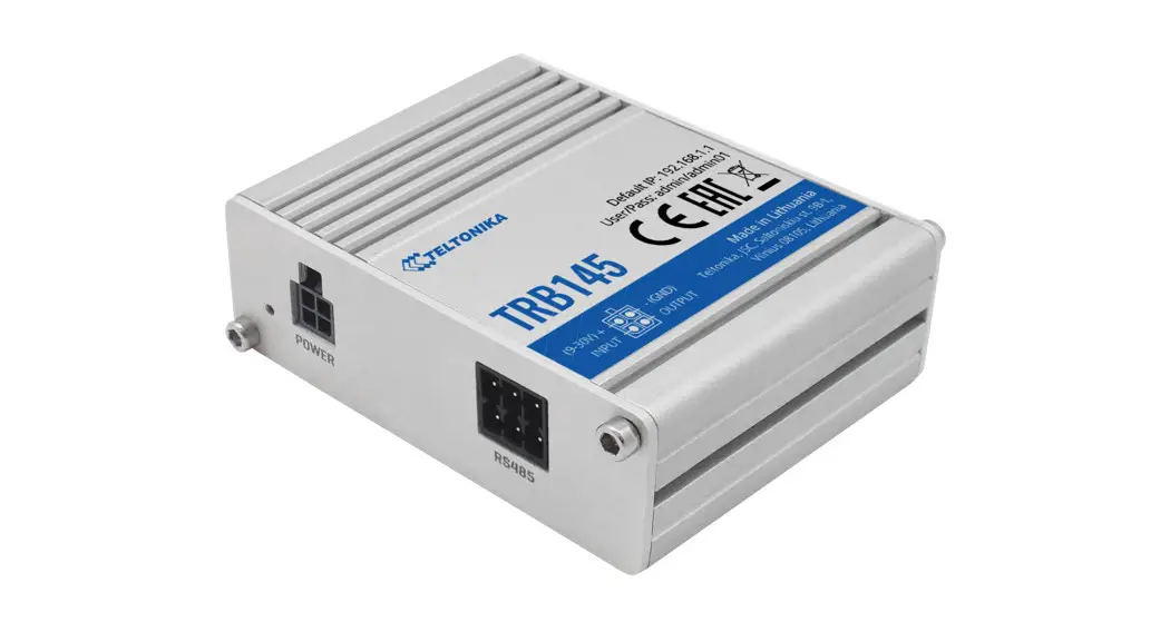
TRB145
Quick Start Guide v2.5
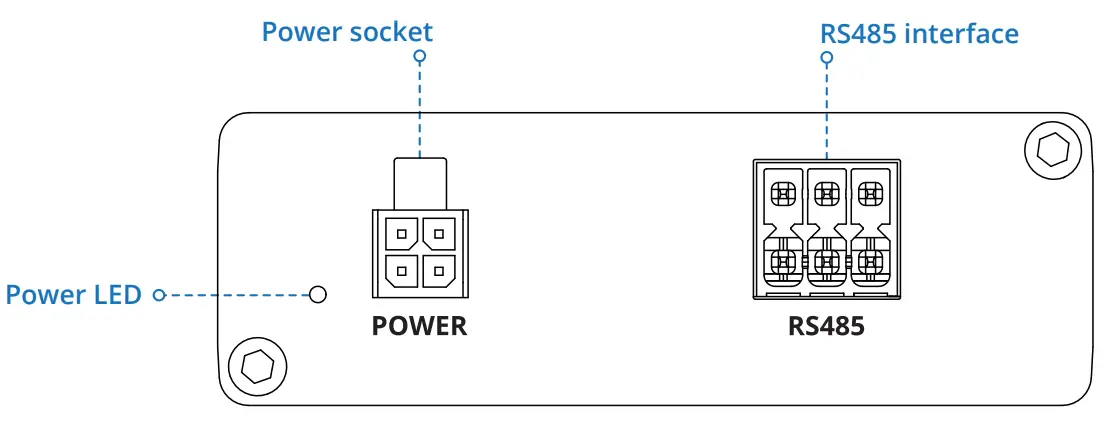
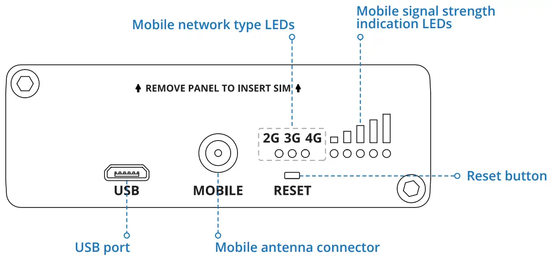
| FRONT VIEW | FRONT VIEW |
 |  |
| DB9 CONNECTOR PINOUT | |
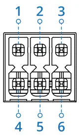 | 1. Driver negative signal (D-). 2. Receiver negative signal (R-). 3. Ground (GND). 4. Driver positive (D+). 5. Receiver positive signal (R+). 6. Power input 9-30 VDC (Vin). |
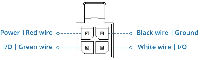
POWER SOCKET PINOUT
HARDWARE INSTALLATION
| 1. Unscrew two back panel hex bolts and remove the back panel. 2. Insert your SIM card into the SIM socket. 3. Attach the panel and tighten the hex bolts. 4. Attach the mobile antenna (max torque 0.4 N·m / 3.5 lbf·in) and connect the USB cable. | 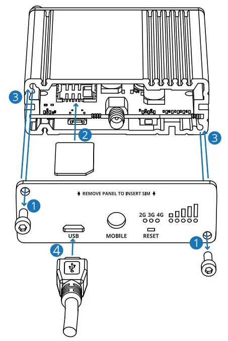 |
DEVICE CONFIGURATION
- Power on the device and connect the USB cable to your computer.
- Allow the gateway to boot up. This might take up to 30 seconds.
- Your computer’s OS should detect the USB device and install the driver.
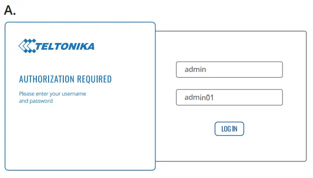
- To enter the gateway’s Web interface (WebUI), type http://192.168.2.1 into the URL field of your Internet browser.
- Use login information shown in image A when prompted for authentication.
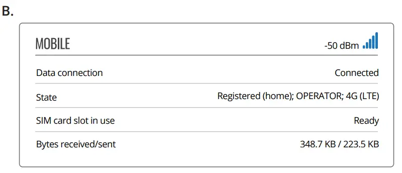
- After logging in pay attention to the Signal Strength indication displayed in the Mobile widget (image B). To
maximize the cellular performance try adjusting the antennas or changing the location of your device to achieve the best signal conditions.
 |  |
TECHNICAL INFORMATION
Radio specifications | |
| RF technologies | 2G, 3G, 4G |
| Max RF power | 33 dBm@GSM, 24 dBm@WCDMA, 23 dBm@LTE |
Bundled accessories specifications* | |
| Power adapter | Input 0.4 Ag100-240 VAC, Output 9 VDC, 0.5 A, 4-pin plug |
| Mobile antenna | 699-868 / 1850-2690 MHz, 50 a VSWR<3, gain** 1 dBi, omnidirectional, SMA male connector |
*Order code dependent.
**Higher gain antenna can be connected to compensate for cable attenuation when a cable is used. The user is responsible for compliance with the legal regulations.
SAFETY INFORMATION
TRB145 gateway must be used in compliance with any and all applicable national and international laws and with any special restrictions regulating the utilization of the communication module in prescribed applications and environments.
Hereby, TELTONIKA NETWORKS declares that this TRB145 is in compliance with the essential requirements and other relevant provisions of
Directive 2014/53/EU.
Instruction Manual: Connect the power adapter to turn on the device. Open 192.168.2.1 in your web browser to configure it. More information on
https://wiki.teltonika-networks.com/
The full text of the EU declaration of conformity is available at the following
Internet address: https://wiki.teltonika-networks.com/view/TRB145_CE/RED
![]()
![]()
wiki knowledge base
https://wiki.teltonika-networks.com/

 This sign means that all used electronic and electric equipment should not be mixed with general household waste. This sign means that all used electronic and electric equipment should not be mixed with general household waste. |
www.teltonika-networks.com
©2021 Teltonika Networks


