iSMACONTROLLI iSMA-D-PD Industrial LCD Panel User Manual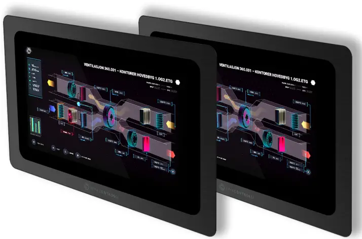
Introduction
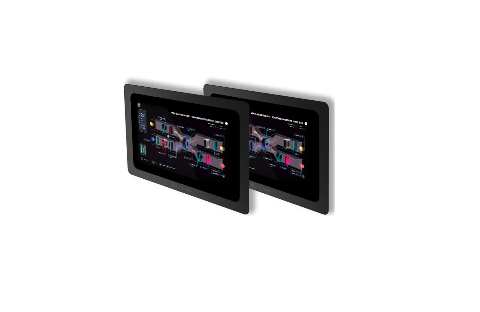
The iSMA-D-PD10C-B1 is 10.1” is an industrial LCD panel, which has been designed to simplify the use of Master Application Controller, iSMA-B MAC36NL.
The LCD panel is equipped with multiple interfaces to accelerate the connection with the master controller. The applied RJ45 interface provides transmitting touch commands (RJ45-USB).
The 16:9 aspect ration with 1366×768 resolution allows for displaying graphics clearly.
The panel is VESA compliant and can be wall-mounted. It has an extensive menu in 7 languages.
Available with EU, UK, and US power supply.
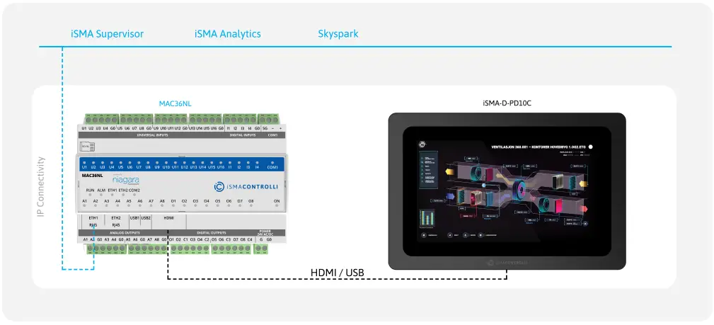
Figure 1. iSMA-D-PD10C-B1 panel connected to the iSMA-B-MAC36NL controller
Revision History
| Rev. | Date | Description |
| 1.0 | 28 Aug 2015 | First edition |
| 1.1 | 31 Mar 2020 | Company data update |
| 1.2 | 25 May 2022 | Rebranded |
Table 1. Revision history
Safety Rules
- Improper wiring of the product can damage it and lead to other hazards. Make sure that the product has been correctly wired before turning the power on.
- Before wiring or removing/mounting the product, make sure to turn the power off.
Failure to do so might cause an electric shock. - Do not touch electrically charged parts such as power terminals. Doing so might cause an electric shock.
- Do not disassemble the product. Doing so might cause an electric shock or faulty operation.
- Use the product only within the operating ranges recommended in the specification (temperature, humidity, voltage, shock, mounting direction, atmosphere, etc.). Failure to do so might cause a fire or faulty operation.
- Firmly tighten the wires to the terminal. Failure to do so might cause a fire.
- Avoid installing the product in close proximity to high-power electrical devices and cables, inductive loads, and switching devices. Proximity of such objects may cause an uncontrolled interference, resulting in an instable operation of the product.
- Proper arrangement of the power and signal cabling affects the operation of the entire control system. Avoid laying the power and signal wiring in parallel cable trays. It can cause interferences in monitored and control signals.
- It is recommended to power controllers/modules with AC/DC power suppliers. They provide better and more stable insulation for devices compared to AC/AC transformer systems, which transmit disturbances and transient phenomena like surges and bursts to devices. They also isolate products from inductive phenomena from other transformers and loads.
- Power supply systems for the product should be protected by external devices limiting overvoltage and effects of lightning discharges.
- Avoid powering the product and its controlled/monitored devices, especially high power and inductive loads, from a single power source. Powering devices from a single power source causes a risk of introducing disturbances from the loads to the control devices.
- If an AC/AC transformer is used to supply control devices, it is strongly recommended to use a maximum 100 VA Class 2 transformer to avoid unwanted inductive effects, which are dangerous for devices.
- Long monitoring and control lines may cause loops in connection with the shared power supply, causing disturbances in the operation of devices, including external communication. It is recommended to use galvanic separators.
- To protect signal and communication lines against external electromagnetic interferences, use properly grounded shielded cables and ferrite beads.
- Switching the digital output relays of large (exceeding specification) inductive loads can cause interference pulses to the electronics installed inside the product. Therefore, it is recommended to use external relays/contactors, etc. to switch such loads. The use of controllers with triac outputs also limits similar overvoltage phenomena.
- Many cases of disturbances and overvoltage in control systems are generated by switched, inductive loads supplied by alternating mains voltage (AC 120/230 V). If they do not have appropriate built-in noise reduction circuits, it is recommended to use external circuits such as snubbers, varistors, or protection diodes to limit these effects.
Technical Specification
| Panel Type | HD industrial TFT LCD | |
| Screen Type | LED; backlight lifetime ≥50000 h, | |
| Size | 10.1’’ | |
| Aspect Ratio | 16:9 | |
| Luminance | 300 nit, up to 800 nit | |
| Contrast | 800:1 | |
| Active Area | 222.7×125.2 mm | |
| Display Color | 16.7 M | |
| Point Distance | 0.264 mm | |
| View Angle | 75/75/75/75 | |
| Response Time | ≤5 ms | |
| Installation | Compatible with VESA, for embedding, wall mount | |
| Menu Languages | English, French, German, Spanish, Chinese, Italian, Russian | |
| Touch Type | 10-point capacitive touch screen | |
| Material | Metal/aluminum alloy | |
| Signal Port | VGA, HDMI, DVI | |
| Power Port | 12 V- 24 V DC | |
| Audio Port | Audio I/O | |
| Touch Port | RJ45 (customized USB) | |
| Anti-interference | Anti-interference electromagnetic compatibility; electromagnetic interference | |
| Anti-Vibration | 5-19 HZ/1.0 mm amplitude; 19-200 HZ/1.0 g accelerated speed | |
| Temperature | Operating temperature: -10°C to 60°C (14°F to 140°F) | Storage temperature: -10°C to 60°C (14°F to 140°F) |
| Humidity | Operation humidity: 10% to 80% | Storage humidity: 10% to 90% |
| Anti-static | 4 KV-8 KV; (customized MAX 16 KV) | |
| Rated Voltage | 100 V AC~240 V to 12 V-24 V DC | |
| Rated Frequency | 50 Hz/60 Hz | |
| Power Supply | 110-240 V AC, 50/60 Hz | |
| Power | Power consumption ≤ 30 W | Power standby ≤ 1.5 W |
| Dimension | 293,6×193,6×48,5 mm (11.560×7.622×1.909 in) | |
| IP | IP65 – for front panel | |
Table 2. Technical specification
Standards and Norms
EN 55032:2015
Electromagnetic compatibility of multimedia equipment. Emission Requirements.
EN 61000-3-2:2014
Electromagnetic compatibility (EMC). Limits for harmonic current emissions for equipment input current ≤ 16 A per phase).
EN 61000-3-3:2013
Electromagnetic compatibility (EMC). Limits for voltage changes, voltage fluctuations and flicker in public low-voltage supply systems, for equipment with rated current ≤ 16 A per phase.
EN 55024:2010 + A1:2015
Information technology equipment. Immunity characteristics. Limits and methods of measurement.
EN 60950-1:2006 + A11:2002 + A1:2010 + A12:2011 + A2:2013
Information technology equipment. Safety General requirements specifies requirements intended to reduce risks of fire, electric shock or injury for the OPERATOR and layman who may come into contact with the equipment and, where specifically stated, for a SERVICE PERSON.
Dimensions
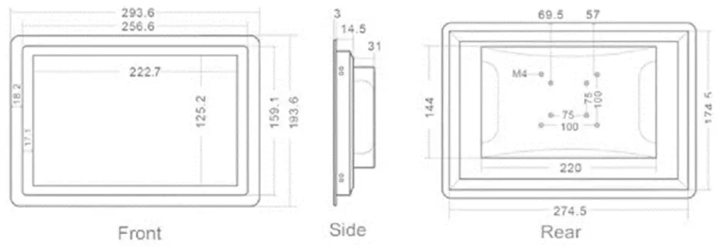
Figure 2. Dimensions of iSMA-D-PD10C-B1
Interfaces
The monitor recognizes and selects the signal automatically.
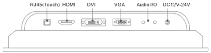
Figure 3. Interface details
Operation Guide
Rear Navigation Buttons
The rear navigation buttons are used to turn the device on and off. Brightness +/- buttons are prepared for future development:
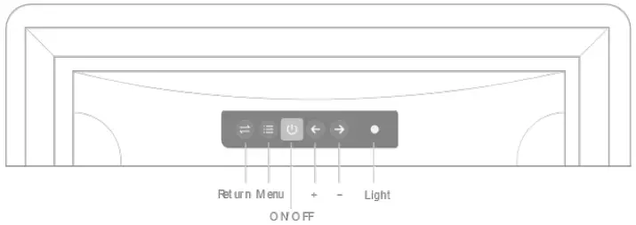
Figure 4. Rear navigation buttons
| Symbol | Name | Instruction |
| Left | Choose + | Choosing different submenus, the function of this button is the change of data quantity. |
| Right | Choose – | |
| ON/OFF | On / off button | Start-up/Shut down the monitor. |
| Return | Back button | Return to the up level menu. |
| Menu | Main menu | First time this button is pressed, OSD will pop-up. |
Table 3. Operating of rear navigation buttons
OSD Options – Adjustment
OSD menu’s basic functions:
- Screen display effect adjustment;
- Brightness adjustment;
- Contrast ratio adjustment;
- Color adjustment;
- etc.
If order to enter the OSD menu interface, go into trial testing of below parameters by clicking main MENU options.
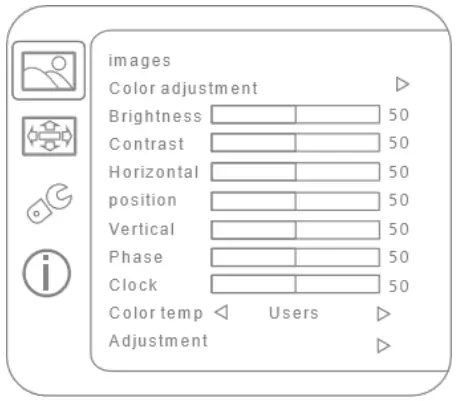
Figure 5. Images adjustment

Figure 6. Menu adjustment
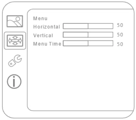
Figure 7. Settings adjustment
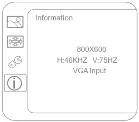
Figure 8. Information menu
Installation
- Do not place the monitor next to the radiator or heat source.
- Do not let any objects press or twine around the power cable or VGA cable.
- Do not place the monitor near to water source or humid places.
- Do not block off the back vents which can dissipate heat generated inside it to prevent damage of components.
Snap Joint Installation
Follow the below steps to install the monitor with four snap joints buckle hole:

Figure 9. Snap joint installation
Wall Mount Installation
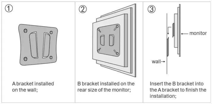
Figure 10. Wall mount installation
![]()


