
Pioneer DR024GHFD18HT2 High Efficiency Air Handler

IMPORTANT NOTICE: Thank you very much for purchasing this Air Conditioner. Please read this manual carefully before installing or operating your new air conditioning system. Be sure to save this manual for future reference.
SAFETY SUMMARY
IMPORTANT NOTICE
- We pursue a policy of continuing improvement in design and performance of products. The right is therefore reserved to vary specifications without notice.
- We cannot anticipate every possible circumstance that might involve a potential hazard.
- This air conditioner is designed for standard air conditioning only. Do not use this air conditioner for other purposes such as drying clothes, refrigerating foods or for any other cooling or heating process. Do not let the air-out face animals or plants, it might have an adverse effect on them.
- The installer and system specialist shall secure safety against leakage according to local regulations or standards.
- Signal words (DANGER, WARNING and CAUTION) are used to identify levels of hazard seriousness. Definitions for identifying hazard levels are provided below with their respective signal words.
DANGER
Immediate hazards which WILL result in severe personal injury or death.
WARNING
Hazards or unsafe practices which COULD result in severe personal injury or death.
CAUTION
Hazards or unsafe practices which COULD result in minor personal injury or product or property damage.
NOTE
Useful information for operation and/or maintenance
- Installation should be performed by the dealer or other professional personnel. Improper installation may cause water leakage, electrical shock, or fire.
DANGER
- Do not perform installation work, refrigerant piping work, drain piping and electrical wiring connection without referring to our installation manual. If the instructions are not followed, it may result in water leakage, electric shock or fire.
- Use refrigerant R410A in the refrigerant cycle.
- Do not pour water into the indoor or outdoor unit. These products are equipped with electrical parts. If poured, it will cause a serious electrical shock.
- Do not open the service cover or access panel for the indoor or outdoor units without turning OFF the main power supply.
- Do not touch or adjust safety devices inside the indoor or outdoor units. If these devices are touched or readjusted, it may cause a serious accident.
- Refrigerant leakage can cause difficulty in breathing due to insufficient air. Turn OFF the main switch, extinguish any naked flames and contact your service contractor, if refrigerant leakage occurs.
- Do perform air-tight test. Do not charge oxygen, acetylene or other flammable and poisonous gas into the refrigerant cycle when performing a leakage test or an air-tight test. These types of gas are extremely dangerous and can cause an explosion. It is recommended that nitrogen be used for this test.
- The installer and system specialist shall secure safety against refrigerant leakage according to local regulations or standards.
- Use an ELB (Electric Leakage Breaker). In the event of a fault, there is danger of an electric shock or a fire if it is not used.
WARNING
- Do not use any sprays such as insecticide, lacquer, hair spray or other flammable gas within approximately one (1) meter from the system.
- If circuit breaker or fuse is often activated, stop the system and contact your service contractor.
- Check that the ground wire is securely connected. If the unit is not correctly grounded, it will lead to electric shock. Do not connect the ground wiring to gas piping, water piping, lightning conductor or ground wiring for the telephone.
- Before performing any brazing work, check to ensure that there is no flammable material around when using refrigerant. Be sure to wear leather gloves to prevent cold injuries.
- Protect the wires, electrical parts, etc. from rats or other small animals. If not protected, rats may gnaw at unprotected parts, which may lead to fire.
- Fix the cables securely. External forces on the terminals could lead to a fire.
- Install the air conditioner on a solid base that can support the unit weight. An inadequate base or incomplete installation may cause injury in the event the unit falls off the base. Incomplete connections or clamping may cause terminal overheating or fire.
- Make sure that the outdoor unit is not covered with snow or ice, before operation.
CAUTION
- Do not step or put any material on the product.
- Do not put any foreign material on the unit or inside the unit.
NOTE
- It is recommended that the room be ventilated every 3 to 4 hours.
- The air conditioner may not work properly under the following circumstances. The power transformer provides the same power with the air conditioner. The electrical equipment is too close to the power supply of the air conditioner. With the sharp change of power consumption and switching action, the power supply of the air conditioner will generate a large induction surge voltage.
CHECKING PRODUCT RECEIVED
- Upon receiving this product, inspect it for any shipping damage. Claims for damage, either apparent or concealed, should be filed immediately with the shipping company.
- Check the model number, electrical characteristics (power supply, voltage and frequency) and accessories to determine if they are correct. The standard utilization of the unit shall be explained in these instructions. Therefore, the utilization of the unit other than those indicated in these instructions is not recommended.
Please contact your local agent, as the occasion arises.
GENERAL
Features
- Being equipped with TXV metering, supporting cooling and heating.
- Multi-speed ECM blower motor
- Selecting electric heater kits within available models.
- Up to 0.8W.C ESP.
- Being in accordance with ETL AHRI.
Product Lineup
| Model (Btu/h) Type | 24K | 36K | 48K | 60K |
| Air Handler | . | . | . | . |
Nomenclature
- DR024GHFD18HT2
- DR036GHFD18HT2
- DR048GHFD18HT2
- DR060GHFD18HT2
Unit Installation
system is the only compatible combination. (Only one indoor unit can be connected with one outdoor unit.)
Working Range
Power Supply
| Working Voltage | 198V ~ 253V |
| Voltage Imbalance | Within a 3% deviation from each voltage at the main terminal of outdoor unit |
| Starting Voltage | Higher than 85% of the Rated Voltage |
Storage Condition
- Temperature -13~140℉ (-25~60℃)
- Humidity 30%~80%
Product Appearance 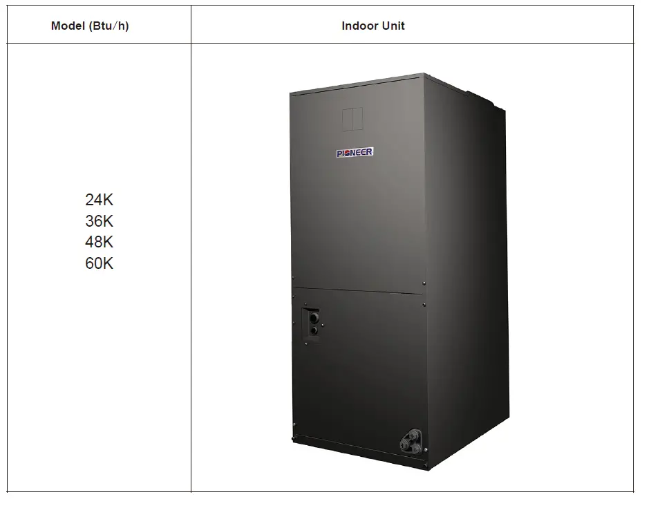
SPECIFICATIONS
| Indoor model | 24K | 36K | 48K | 60K | ||
| Type | US Duct | US Duct | US Duct | US Duct | ||
| Power Supply | V/ph/Hz | 208~230/1/60 | 208~230/1/60 | 208~230/1/60 | 208~230/1/60 | |
|
Cooling | Capacity | Btu/h | 24000 | 36000 | 48000 | 56000 |
| Capacity (min.-max.) | Btu/h | 6700-26000 | 11800-36800 | 18300-52000 | 18300-59400 | |
| Capacity (min.-max.) | W | 2227-7327 | 2814-10697 | 5363-15240 | 5363-17409 | |
| Input | W | 2200 | 3770 | 4690 | 6560 | |
| Current | A | 9.6 | 16.5 | 21.0 | 26.8 | |
| SEER1 | Btu/(W.h) | 18 | 18 | 17.5 | 17.5 | |
| SEER2 | Btu/(W.h) | 17 | 17.5 | 17 | 17 | |
| EER | Btu/(W.h) | 10.90 | 9.55 | 10.24 | 8.53 | |
|
Heating | Capacity | Btu/h | 24000 | 36000 | 48000 | 56000 |
| Capacity(min.-max.) | Btu/h | 6700-26000 | 8900-38200 | 17600-52000 | 17600-57500 | |
| Capacity Heating(Rated) @ 47°F | Btu/h | 24000 | 36000 | 48000 | 56000 | |
| Capacity Heating(Rated) @ 17°F | Btu/h | 16000 | 25000 | 29300 | 32400 | |
| Input | W | 2000 | 3200 | 4260 | 5290 | |
| Current | A | 8.7 | 14.1 | 19.0 | 21.0 | |
| HSPF1 | Btu/(W.h) | 10 | 11 | 10 | 10 | |
| HSPF2 | Btu/(W.h) | 9 | 9 | 8 | 8 | |
| COP | W/W | 3.5 | 3.3 | 3.3 | 3.1 | |
| COP | Btu/(W.h) | 11.95 | 11.26 | 11.26 | 10.58 | |
| Moisture Removal | L/h | 2.2 | 4.5 | 5.5 | 7.50 | |
| Pts/h | 4.64 | 9.5 | 11.6 | 15.80 | ||
| Min. Ampacity | A | Indoor3.3 | Indoor4.8 | Indoor6.8 | Indoor6.8 | |
| Max. td Fuse/ Breaker | A | Indoor10 | Indoor10 | Indoor15 | Indoor15 | |
| Power Cable | No.× AWG | Indoor3×16, | Indoor3×16 | Indoor3×16 | Indoor3×16 | |
| Communication Cable | No. × AWG | 5×16 | 5×16 | 5×16 | 5×16 | |
| Thermostat Type | Common 24V Thermostat | Common 24V Thermostat | Common 24V Thermostat | Common 24V Thermostat | ||
| Indoor Fan Motor (Multi Speed ECM) | Qty | 1 | 1 | 1 | 1 | |
| Model | ZWK702B006073 | ZWK702B500026 | ZKSD-560-8-50-14 | ZKSD-560-8-58 | ||
| Output | HP | 1/3 | 1/2 | 3/4 | 3/4 | |
| RLA | A | 2.4~2.6 | 3.6~3.8 | 5.0~5.4 | 5.0~5.4 | |
| Speed | r/min | 350~1400 | 350~1400 | 350~1400 | 350~1400 | |
| Indoor Air Flow Rated | m3/h | 1360 | 1905 | 2700 | 2900 | |
| Indoor Air Flow Rated | CFM | 800 | 1120 | 1588 | 1706 | |
|
Indoor Coil | Number of Rows | 4 | 4 | 5 | 5 | |
| Tube Pitch(a) | mm | 21 | 21 | 21 | 21 | |
| in | 0.827 | 0.827 | 0.827 | 0.827 | ||
| Row Pitch(b) | mm | 13.6 | 13.6 | 13.6 | 13.6 | |
| in | 0.535 | 0.535 | 0.535 | 0.535 | ||
| Fin Spacing | mm | 1.4 | 1.4 | 1.5 | 1.5 | |
| Fins Per in | 18 | 18 | 17 | 17 | ||
| Fin Type | Hydrophilic Aluminium | Hydrophilic Aluminium | Hydrophilic Aluminium | Hydrophilic Aluminium | ||
| Tube outside Diameter and Type | mm | Ф7,Innergroove Tube | Ф7,Innergroove Tube | Ф7,Innergroove Tube | Ф7,Innergroove Tube | |
| Coil | mm | 2(444×420×54.4) | 2(444×420×54.4) | 2 (509×546×68) | 2 (509×546×68) | |
| Indoor model | 24K | 36K | 48K | 60K | ||
| Indoor Coil | Dimension(W×H×D) | in | 2(17-1/2×16-1/2× 2-1/8) | 2(17-1/2×16-1/2×2-1 /8) | 2 (20×21-1/2×2- 11/16) | 2 (20×21-1/2×2- 11/16) |
| Number of Circuits | 8 | 8 | 12 | 12 | ||
| ESP | Rated | In.W.C. (Pa) | 0.18(45) | 0.228(57) | 0.276(70) | 0.276(70) |
| Range | In.W.C. (Pa) | 0-0.8(0-200) | 0-0.8(0-200) | 0-0.8(0-200) | 0-0.8(0-200) | |
| Indoor Noise Level (Hi) | dB(A) | 55 | 57 | 64 | 65 | |
| Throttle Type | TXV | TXV | TXV | TXV | ||
|
Indoor Unit | Dimension (W×H×D) | mm | 500×1170×550 | 500×1170×550 | 560×1370×610 | 560×1370×610 |
| inch | 19-5/8 × 46-1/8 × 21-5/8 | 19-5/8 × 46-1/8 × 21-5/8 | 22×53-7/8×24 | 22×53-7/8×24 | ||
| Packing(W×H×D) | mm | 570×1260×645 | 570×1260×645 | 640×1410×710 | 640×1410×710 | |
| inch | 22-1/2×49-5/8× 25-3/8 | 22-1/2×49-5/8× 25-3/8 | 25-1/4×55-1/2×28 | 25-1/4×55-1/2×28 | ||
| Net Weight | kg | 61.5 | 63.5 | 85 | 85 | |
| lbs | 135.5 | 140 | 187.2 | 187.2 | ||
| Shipping Weight | kg | 72 | 74 | 97 | 97 | |
| lbs | 158.6 | 163.1 | 214 | 214 | ||
| Drainage Water Pipe Diameter | inch | 3/4” | 3/4” | 3/4” | 3/4” | |
| Design Pressure | H/L | MPa | 3.8/1.6 | 3.8/1.6 | 3.8/1.6 | 3.8/1.6 |
| PSIG | 550/240 | 550/240 | 550/240 | 550/240 | ||
| Qty’per 20’ /40’ /40’HQ (Indoor Unit) | Set | 36/72/144 | 36/72/144 | 39/78/102 | 39/78/102 | |
NOTE:
- Test Conditions:
- Rated Capacity Test Conditions:
Cooling: Indoor: DB 80.0℉ (26.7C) /WB 67.0℉ (19.4C)
Outdoor: DB 95.0℉ (35.0C) /WB 75.0℉ (23.9C) Heating: Indoor: DB 70.0℉ (21.1C) /WB 60.0℉ (15.6C)
Outdoor: DB 47℉ (8.3C) /WB 43℉ (6.1C) - SEER & HSPF Test Standard: AHRI 210/240.
- Rated Capacity Test Conditions:
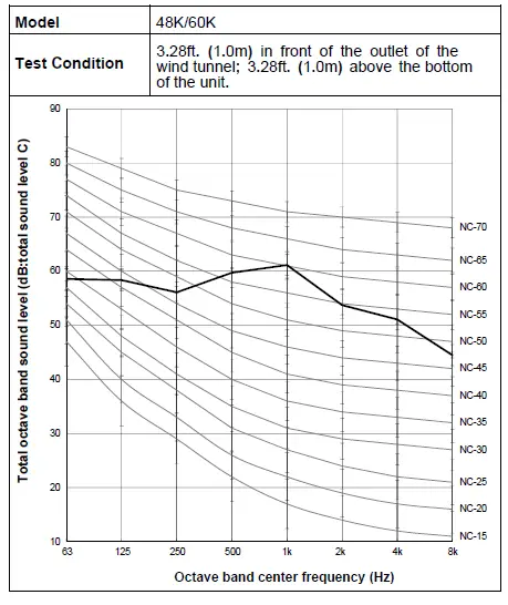
- The Sound Pressure Level is based on the following conditions:
Indoor Unit:
Air Handler Unit
Measure the noise value of the point 3.28 ft(1.0m) in front of the outlet of the wind tunnel and 3.28 ft (1.0m) high from the bottom of the unit. - The above data was measured in an anechoic chamber. Please take into consideration the reflected sound of your specific application environment.
- All specifications are subject to change by the manufacturer without prior notice.
OUTLINES AND DIMENSIONS
24K/36K 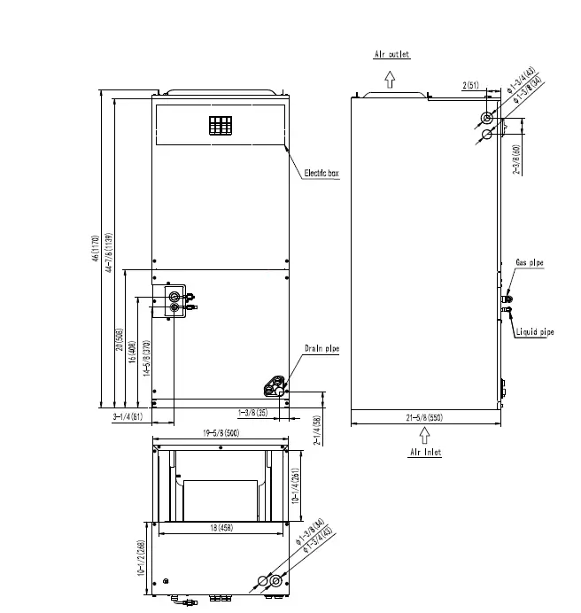
48K/60K 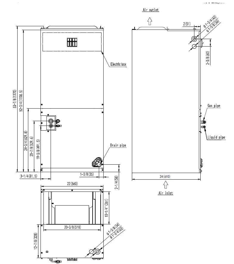
Electrical Data
|
Indoor Unit | Power Supply | Applicable Voltage | ELB | ||||
| Voltage (V) | PH | Frequency (Hz) | Umin. (V) | Umax. (V) | Nominal Current (A) | Nominal Sensitive Current (mA) | |
|
24K/36K/ 48K/60K |
208/230 |
1 |
60 |
198 |
253 |
15 |
30 |
NOTE:
- The above compressor data is based on 100% capacity combination of indoor units at the rated operating frequency.
- This data is based on the same conditions as the nominal heating and cooling capacities.
- The compressor is started by an inverter, resulting in extremely low starting current.
BLOWER DATA
Airflow performance data is based on cooling performance with a coil and no filter in place. Check the performance table for appropriate unit size selection. External static pressure should stay within the minimum and maximum limits shown in the table below in order to ensure proper cooling, heating , and electric heating operation.
Air Flow Table
| Air Handler Model | Motor Speed | External Static Pressure in.H2O[KPa] | |||||||||
| 0[0] | 0.1[0.02] | 0.18[0.045] | 0.3[0.07] | 0.4[0.1] | 0.5[0.12] | 0.6[0.15] | 0.7[0.17] | 0.8[0.20] | |||
|
24K | Tap(1) -Default Setting | CFM | 815 | 792 | 752 | 709 | 676 | 653 | 615 | 566 | 512 |
| Watts | 94 | 102 | 110 | 123 | 130 | 139 | 148 | 157 | 167 | ||
| Tap(2) | CFM | 862 | 828 | 792 | 735 | 705 | 673 | 661 | 618 | 561 | |
| Watts | 106 | 114 | 125 | 137 | 145 | 154 | 161 | 170 | 177 | ||
| Tap(3) | CFM | 975 | 940 | 906 | 859 | 853 | 803 | 769 | 735 | 681 | |
| Watts | 148 | 155 | 165 | 178 | 185 | 193 | 203 | 213 | 219 | ||
| Tap(4) | CFM | 1055 | 1024 | 995 | 948 | 922 | 895 | 864 | 825 | 779 | |
| Watts | 197 | 204 | 214 | 228 | 234 | 241 | 251 | 258 | 267 | ||
| Air Handler Model | Motor Speed | External Static Pressure in.H2O[KPa] | |||||||||
| 0[0] | 0.1[0.02] | 0.18[0.045] | 0.3[0.07] | 0.4[0.1] | 0.5[0.12] | 0.6[0.15] | 0.7[0.17] | 0.8[0.20] | |||
|
36K | Tap(1) -Default Setting | CFM | 1264 | 1216 | 1172 | 1135 | 1096 | 1028 | 954 | 890 | 839 |
| Watts | 215 | 222 | 233 | 238 | 244 | 254 | 261 | 266 | 274 | ||
| Tap(2) | CFM | 1350 | 1314 | 1269 | 1206 | 1116 | 1082 | 1050 | 990 | 930 | |
| Watts | 257 | 264 | 274 | 282 | 292 | 297 | 302 | 309 | 316 | ||
| Tap(3) | CFM | 1460 | 1409 | 1368 | 1323 | 1266 | 1192 | 1122 | 1060 | 999 | |
| Watts | 280 | 288 | 295 | 304 | 313 | 323 | 333 | 340 | 348 | ||
| Tap(4) | CFM | 1526 | 1479 | 1441 | 1399 | 1350 | 1292 | 1221 | 1148 | 1088 | |
| Watts | 342 | 348 | 355 | 363 | 371 | 381 | 394 | 401 | 406 | ||
- Required 350-450CFM/ton range.
- CFM means Standard Cubic Foot per Hour.
- When there is an electric heater, please set the fan speed based on the air volume that the electric heater needs (not less than 350CFM/TON).
- Airflow based upon Air Handler Unit operates at 230V with no electric heater kit and no filter. Airflow at 208V is approximately the same as 230V.
| Air Handler Model | Motor Speed | External Static Pressure in.H2O[KPa] | |||||||||
| 0[0] | 0.1[0.02] | 0.18[0.045] | 0.3[0.07] | 0.4[0.1] | 0.5[0.12] | 0.6[0.15] | 0.7[0.17] | 0.8[0.20] | |||
|
48K | Tap(1) -Default Setting | CFM | 1756 | 1701 | 1626 | 1579 | 1520 | 1468 | 1425 | 1386 | 1346 |
| Watts | 348 | 357 | 369 | 378 | 387 | 395 | 407 | 410 | 424 | ||
| Tap(2) | CFM | 1799 | 1746 | 1678 | 1634 | 1571 | 1522 | 1449 | 1402 | 1241 | |
| Watts | 366 | 377 | 388 | 398 | 410 | 419 | 428 | 444 | 440 | ||
| Tap(3) | CFM | 1828 | 1794 | 1749 | 1719 | 1670 | 1633 | 1589 | 1553 | 1510 | |
| Watts | 376 | 387 | 401 | 413 | 428 | 437 | 452 | 465 | 482 | ||
| Tap(4) | CFM | 1888 | 1855 | 1813 | 1782 | 1735 | 1701 | 1665 | 1626 | 1585 | |
| Watts | 415 | 428 | 445 | 456 | 469 | 481 | 495 | 510 | 525 | ||
| Air Handler Model | Motor Speed | External Static Pressure in.H2O[KPa] | |||||||||
| 0[0] | 0.1[0.02] | 0.18[0.045] | 0.3[0.07] | 0.4[0.1] | 0.5[0.12] | 0.6[0.15] | 0.7[0.17] | 0.8[0.20] | |||
|
60K | Tap(1) -Default Setting | CFM | 1838 | 1810 | 1770 | 1760 | 1670 | 1633 | 1589 | 1553 | 1510 |
| Watts | 376 | 387 | 401 | 413 | 428 | 437 | 452 | 465 | 482 | ||
| Tap(2) | CFM | 1888 | 1855 | 1813 | 1782 | 1751 | 1701 | 1665 | 1626 | 1585 | |
| Watts | 415 | 428 | 445 | 456 | 469 | 481 | 495 | 510 | 525 | ||
| Tap(3) | CFM | 1971 | 1941 | 1893 | 1864 | 1820 | 1786 | 1755 | 1718 | 1673 | |
| Watts | 472 | 485 | 501 | 513 | 530 | 540 | 558 | 568 | 586 | ||
| Tap(4) | CFM | 2056 | 2022 | 1978 | 1950 | 1907 | 1878 | 1826 | 1801 | 1750 | |
| Watts | 533 | 545 | 562 | 575 | 592 | 603 | 619 | 631 | 638 | ||
SOUND PRESSURE DATA
Indoor Unit 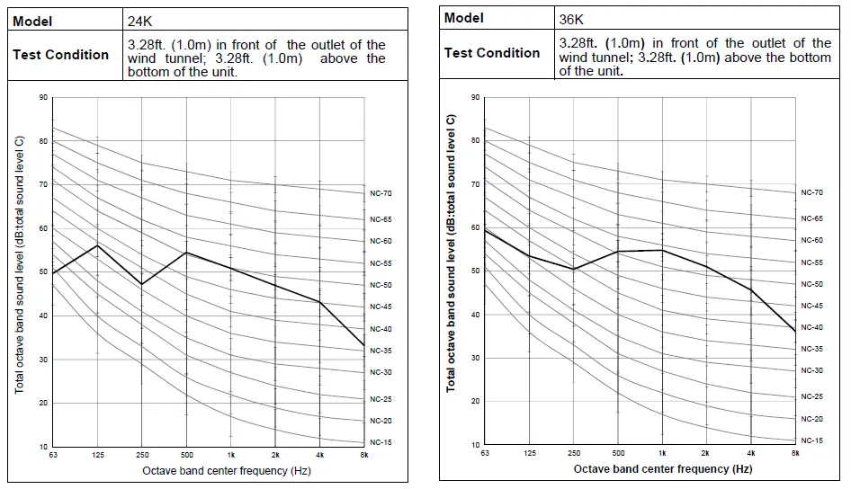
Refrigerant Cycle
Indoor Unit
24K/36K/48K/60K 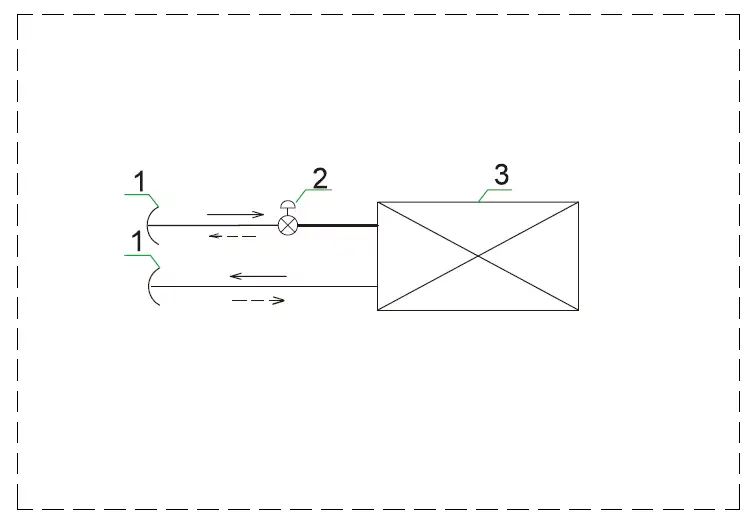
List of Components
- Hexagon Nut
- TXV
- Indoor Heat Exchanger
WIRING DIAGRAM
Electrical Wiring Diagram
Electrical Wiring Diagram 2157413.B 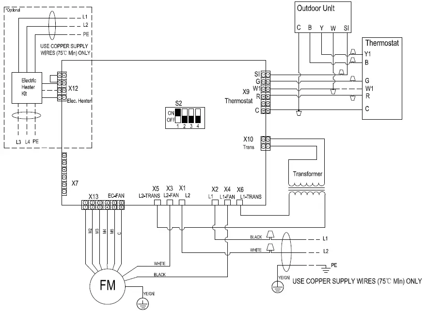
NOTES:
- Use copper wire (75℃ Min) only between disconnect switch and unit.
- To be wired in accordance with NEC and local codes.
- If any of the original wire supplied must be replaced, use the same or equivalent type.
- Connect R to R, G to G,etc. See Installation Instruction for details.
- Check airflow table to ensure appropriate operations.
- The EHK is optional. If EHK needs to be installed, please see Wiring Diagram of EHK for wiring details.
- The dashed line means that the component or wire are optional.
- The DIP switch S2 in the diagram is the factory default configuration. In actual use, please set S2 to choose blower speed according to the value of static pressure.
- Please don’t connect the wire(W1) from controller to indoor, if there is no EHK.
Control Board Picture 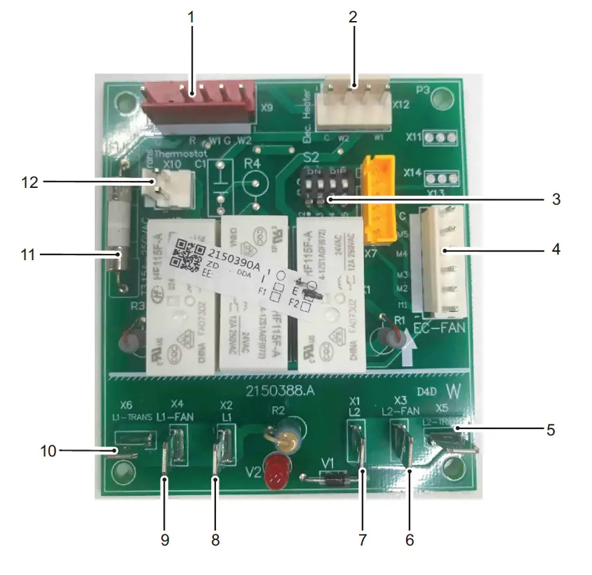
| NO. | Description | NO. | Description |
| 1 | Thermostat | 7 | AC Power L2 |
| 2 | Electrical Heat Kit | 8 | AC Power L1 |
| 3 | DIP Switch for Blower Speed | 9 | L1 for Fan Motor |
| 4 | Fan Motor Control | 10 | L1 for Transformer |
| 5 | L2 for Transformer | 11 | Fuse |
| 6 | L2 for Fan Motor | 12 | AC 24V from Transformer |
Common Wiring
Wiring Diagram 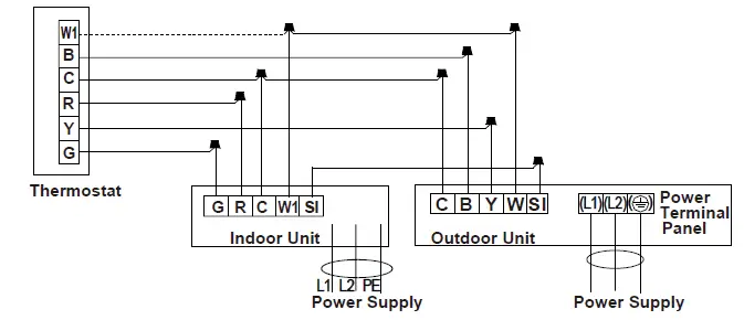
NOTE:
- Do not connect dashed line when electric heater is not used.
- Wiring must be performed according to wiring diagram that pasted on indoor unit.
- The SI wire between the indoor and outdoor units is not indispensable, especially when the outdoor unit is connected to an indoor unit of a different brand. It is more energy-saving when the outdoor unit is connected to an indoor unit of the same brand by SI wire. However, it still can run without it.
- Since the thermostat is locally provided, the terminal block in the diagram may differ from the actual one. The letter Y is the same as Y1.
Recommended Wire Size
|
Model (Btu/h) |
Power Supply | ELB | Power Source Cable Size |
Transmitting Cable Size |
Thermostat Signal Size |
Fuse or Circuit Breaker (A) | |
| Rated Current (A) | Nominal Sensitive Current (mA) | ||||||
| 24K~60K | 208/230V ~/60Hz |
15 |
30 |
3×16AWG |
5×16AWG | 5×18AWG/ 6×18AWG |
15 |
Max. Running Current (A): REFER TO NAMEPLATE
NOTE:
- Follow local codes and regulations when selecting field wires, and all the above are the minimum wire size.
- When transmitting cable is longer than 262ft. (80m), a larger wire size should be selected.
- Install main switch and ELB for each system separately. Select the high response type ELB that is acted within 0.1 second.
- If auxiliary heater is required and already installed on indoor unit, power source cable should be installed separately and the size should be selected in accordance with UL.
FIELD SETTING
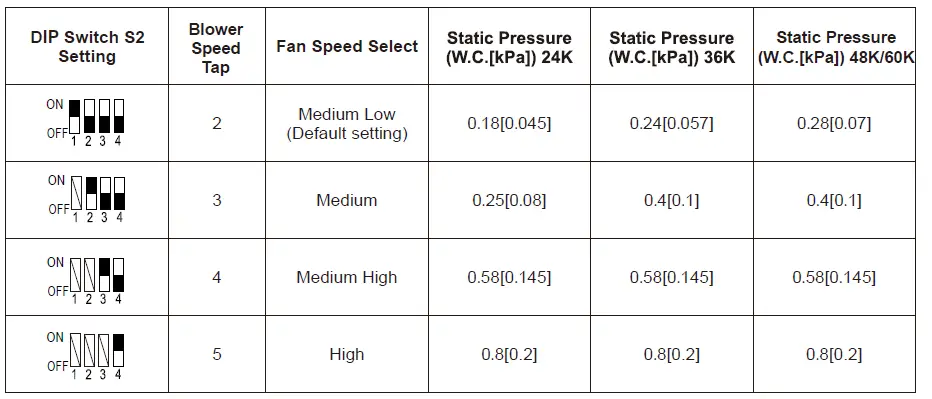
Static Pressure Setting:
NOTE: Symbol ” ” indicates the position of the DIP switch. Symbol ” ” indicates any position of ON or OFF.
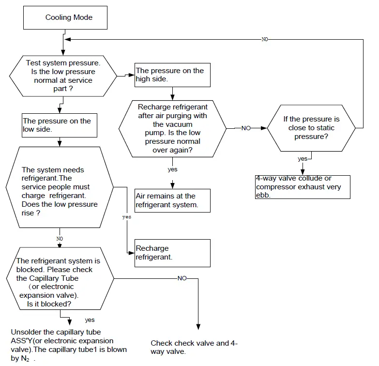
CHECKING COMPONENTS
Check Refrigerant System
TEST SYSTEM FLOW:
Conditions: ① Compressor is running.
The air condition should be installed in good ventilation.
Tool: Pressure Gauge Technique: ① see ② feel ③ test
- See-Tube Defrost.
- Feel —– The Difference between Tube’s Temperature.
- Test —– Test Pressure.


Check Parts Unit 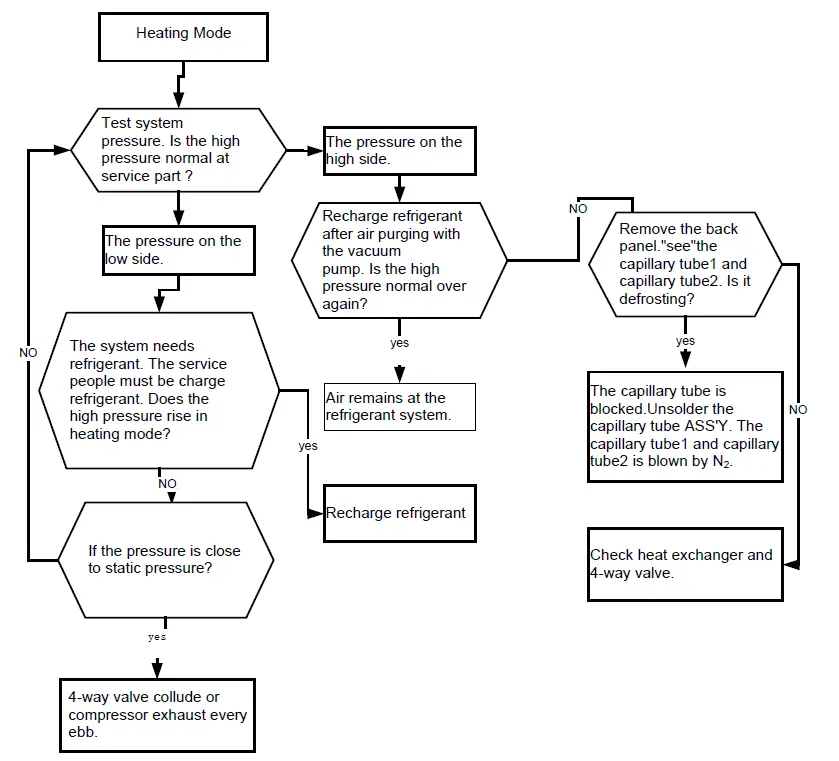
Indoor Unit Fan Motor
- Duct motor model
- 24K: ZWK702B006073
- 36K: ZWK702B500026
- 48K: ZKSD-560-8-50-14
- 60K: ZKSD-560-8-58
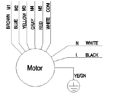
Test in resistance.
TOOL: Multimeter.
Test the resistance of the main winding. The indoor fan motor fails if the resistance of main winding is 0(short circuit)or∞(open circuit).
Test in voltage
TOOL: Multimeter.
Insert screwdriver to rotate indoor fan motor slowly for 1 revolution or over, and measure voltage “YELLOW” and “GND” on motor. The voltage repeat 0V DC and 5V DC.
NOTES:
- Please don’t hold motor by lead wires.
- Please don’t plug IN/OUT the motor connector while power is ON.
- Please don’t drop hurl or dump motor against hard material. Malfunction may not be observed at early stage after such shock. But it may be found later, this type of mishandling void our warranty.
DISASSEMBLY AND ASSEMBLY FOR MOTOR
Indoor Unit
24K/36K/48K/60K 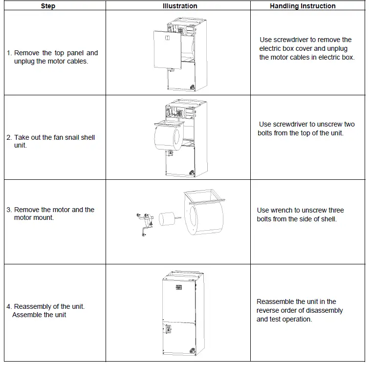
Important: Before disassembly and assembly, make sure that the power to the system has been disconnected and verified as voltage free.
HEATER KIT
| Electric Heat Kit Model | Air Handler Model | Electric Heat (kW) | MIN. Circuit Ampacity | MAX. Fuse or Breaker (HACR) Ampacity | Fan Speed Tap | |||||
| 230VAC | 208VAC | 230VAC | 208VAC | 2 | 3 | 4 | 5 | |||
| 21-4245-01 | 24K | 5 | 28.3 | 25.9 | 30 | 30 | ● | ● | ● | ● |
| 21-4245-02 | 7.5 | 40.7 | 37.2 | 45 | 40 | ╳ | ● | ● | ● | |
| 21-4245-03 | 10 | 53.2 | 48.5 | 60 | 50 | ╳ | ╳ | ● | ● | |
| 21-4245-01 |
36K | 5 | 29.8 | 27.4 | 30 | 30 | ● | ● | ● | ● |
| 21-4245-02 | 7.5 | 42.2 | 38.7 | 45 | 40 | ╳ | ● | ● | ● | |
| 21-4245-03 | 10 | 54.7 | 49.9 | 60 | 50 | ╳ | ╳ | ● | ● | |
| 21-4245-04 | 15 | 42.2+36.9 | 38.6+33.8 | 45+40 | 40+35 | ╳ | ╳ | ╳ | ● | |
| 21-4245-01 |
48K/60K | 5 | 31.8 | 29.4 | 35 | 30 | ● | ● | ● | ● |
| 21-4245-02 | 7.5 | 44.8 | 40.7 | 45 | 45 | ╳ | ● | ● | ● | |
| 21-4245-03 | 10 | 56.7 | 51.9 | 60 | 55 | ╳ | ╳ | ● | ● | |
| 21-4245-04 | 15 | 44.8+36.9 | 40.7+33.8 | 50+40 | 50+35 | ╳ | ╳ | ● | ● | |
| 21-4245-05 | 20 | 56.7+49.9 | 51.9+45.2 | 60+50 | 60+50 | ╳ | ╳ | ╳ | ● | |
NOTES:
- To be wired in accordance with NEC and local codes.
- Fan speed selection: 1–Medium-low; 2–Medium; 3–Medium-high; 4–High.
- The heater kit must be connected to the power supply separately.
- Check if heat kit is suitable for AHU 3-way position installation.
- Ampacities for MCA and Fuse/breaker including the blower motor.
- Heat pump systems require specified airflow. Each ton of cooling requires between 350 and 450 cubic feet of air per minute(CFM), or 400 CFM nominally.
The design and specifications of this product are subject to change without prior notice as development continues. Consult with the sales agency or manufacturer for details. Refer to the equipment nameplate for all other applicable specifications.
Parker Davis HVAC International, Inc.
3250 NW 107 Avenue, Doral, FL 33172 – USA
Tel : (305) 513-4488
Fax : (305) 513-4499
E-mail: [email protected] Website: www.pdhvac.com
Pioneer product line, parts, and supplies are available online for convenient ordering at: www.highseer.com
www.pioneerminisplit.com Scan the below code to visit our support page where you can find more installation materials:


 Air Conditioners Air Handlers Instruction Manual")


