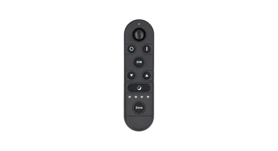
![]() REMOTE CONTROL 2.4 GHZ
REMOTE CONTROL 2.4 GHZ
USER MANUAL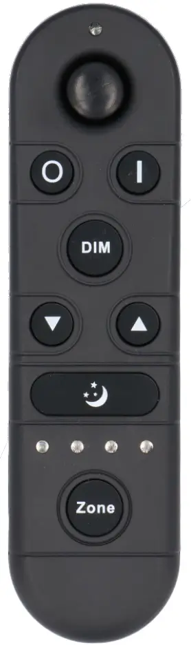
![]() ITL-R-4
ITL-R-4
SKU
PRODUCT FEATURES
- Product supply voltage is 3V(AAA*2);
- Adopt 2.4G wireless control, with feature of long distance and non-directional control;
- Full keys design, unique interface, simple operation;
- Multi zone control function: could control single zone or multiple zones; controlled area indicated by indicator light , more intuitive;
- Multiple installation ways: 3M tape or drill.
TECHNICAL PARAMETERS
| Working temperature | -20 — 60° C | Supply voltage | 3V (AAA*2PCS) |
| Sleep state current | <25uA | Emission current | <30mA |
| Sleep state power consume | <75uW | Emission power | <90mW |
| Net weight | 55g | Product size | L148*W40*38 (mm) |
| Remote control distance | :530m | Emission frequency | 2.4GHz |
| Remote accessories | Remote hanger, 3M foam sponge glue, M4 Double headed self tapping screw, 6 Expanding Tube, Battery, Manual | ||
DIRECTIONS OF USE
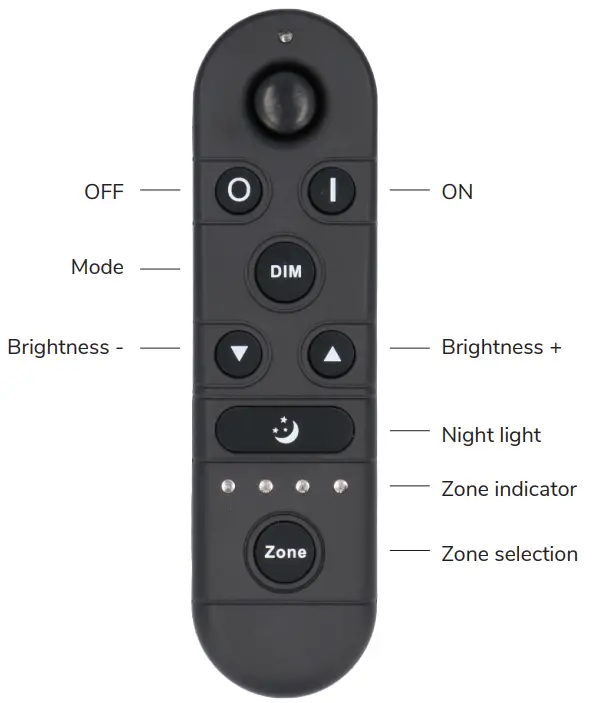
| Name of Key | Instruction |
| ON | ON in any time |
| OFF | OFF in any time |
| Mode | 3 Brightness Grades: 20%, 50%, 100% |
| Brightness – | decrease light brightness, long press continuously |
| Brightness + | Increase light brightness, long press continuously |
| Night light | 5% brightness |
| Zone selection key | Select control zone (selected zone indication light will on, support single zone and overall zones control) |
Remark: Short press Zone Key, for single zone shift, selected zone indication light on. Long press Zone key for 3 seconds, select all zones, 4 indication lights on in the meantime, control all areas lights.
Please pay attention to the following 3 points before operation:
- All equipment in the complete system after installation should have a unified and unique code value, so as to achieve the security and stability of the system.
- The receiver can only store one code value and cannot be overwritten. Before learning the new code value, it is necessary to clear the original code of the receiver; the remote controller can only save one code value but can be overwritten and can also restore the factory settings. In order to facilitate the later maintenance, the three components that may be involved in the system (including receivers, handheld remote controllers, and panel remote controllers) can realize mutual learning of code values.
- Since the receiver performs code value learning in the power-on state, in order to avoid confusion in the area, it is recommended that each area has an independent power switch so that the power of other areas can be easily cut off when the code is being operated.
Code clearing operation: means that the original code value of the receiver will be cleared and returned to the factory state.
Then it can be controlled by any compatible remote controller, and can learn to a new code.
| Step | Operation | Instructions |
| 1 | Connecting the load to the receiver and power it on. | 1.The clearing operation should be finished within 5 minutes after the receiver is powered on. If exceeds the time, can be powered on again. 2.Batch operation can be performed within the remote control range. |
| 2 | Press and hold the remote control “Off” for 10 seconds. The indicator of the remote control flashes quickly, means it enters the clearing code transmission status. There is no need to select the corresponding area when clearing code. | 1.Will automatically exit code transmission status after 60 seconds, or pressing any key to exit. 2.If the original remote controller is lost, the new remote controller can be used for clearing operations. |
| 3 | See the load light flashes 3 times and return to the initial state | Clearing coding is finished successfully |
Code pairing operation: means that the receiver will only be controlled by the value code remote controller.
| Step | Operation | Instructions |
| 1 | Connecting the load to the receiver and power it on. | 1.It is necessary to clear the code first, if the receiver was coded before. 2.Batch operation can be performed within the remote control range. |
| 2 | Select area. | Select the area with the “Zone” key and the corresponding indicator lights up. |
| 3 | Press and hold “ON” on the remote control for 5 seconds, the indicator of the remote control will flash quickly, means it enters the pairing code transmission status. | Will automatically exit code transmission status after 60 seconds, or pressing any key to exit. |
| 4 | See the load light flashes 3 times and return to the initial state. | Pairing coding is finished successfully. |
Code learning operation between remote controls: Used to unify system code values or copy a new remote controls.
Since each remote controller has its own unique code at the time of delivery, when there are multiple remote controllers in one system, one of them (for example, remote controller A) must be selected as the system code value, and the code value of the rest remote controllers (for example, remote controller B) should be copied to the same one.
| Step | Operation | Instructions |
| 1 | A remote control: Press and hold “ON” on the remote control for 5 seconds, the indicator of the remote control will flash quickly, means it enters the pairing code transmission status. | Will automatically exit code transmission status after 60 seconds, or pressing any key to exit. |
| 2 | B remote control: long press “mode key” for 5 seconds, the remote indicator light changes from 100% light to 5% light and flash, means entering the code value receiving state. | Will automatically exit the code value receiving state after 30 seconds, or exit after learning the code value successfully. |
| 3 | see the B remote control indicator light flash 3 times | Code copying is finished and exit code value receiving status. |
The remote controller restores the factory setting: it means that the remote controller will be restored to the factory’s unique code value.
| Step | Operation | Instructions |
| 1 | Long press “mode “for 20 seconds | The remote indicator light dim down and flashes continuously until the 20th second and then back to 100% light. Means this step is finished. |
| 2 | Press the “OFF” to confirm, the remote indicator light flashes 3 times | Restore factory settings successfully. |
ACCESSORIES
|
|
|
|
INSTALLATION INSTRUCTIONS
There are two different installation methods for the remote control rack, customers can choose to install according to the different situations.
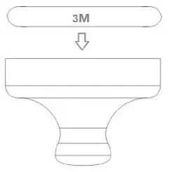
The first installation method: free drilling installation (for flat no ash surface)
- First, tear off the protective film for one side of 3M tape, stick it to the back of the remote control rack;

- Tear off the protective film for other side of 3M tape, and stick the remote control rack on the place where you want to stick the remote control rack.
- Hang the remote control on the rack after installation

The second installation method: free drilling installation(suitable for uneven and ash surface)
- Drill a hole on the wall with a 6mm drill bit;
- Install the expansion tube in the hole;
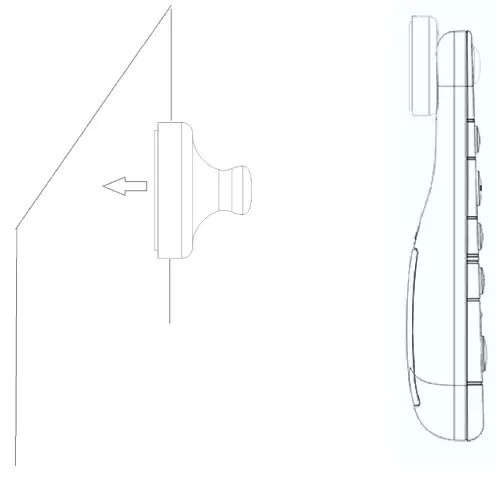
- Twist the tip end of the M4 double-headed self-tapping screw into the expansion tube;

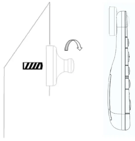
- Install the remote control rack on the screw like below
- Hang the remote control on the rack after installation

INTENDED USE / APPLICATION
Product designed for the use in households and for other similar general applications.
MOUNTING
Technical changes reserved. Read the manual before mounting. Mounting should be performed by an appropriately qualified person. Any activities to be done with disconnected power supply. Exercise particular caution. Product has a protective contact/terminal. Failure to connect the protective lead may lead to electric shock. Mounting diagram: see pictures. Check for proper mechanical fastening and connection to electrical power prior to first use. The product can be connected to a supply network which meets energy quality standards as prescribed by law. To maintain the proper IP protection level, the right diameter of the power cable should be selected for the cable gland used in the product.
FUNCTIONAL CHARACTERISTICS
The product can only be used indoors.
USAGE GUIDELINES / MAINTENANCE
Any maintenance work must be performed when the power supply is cut off and the product has cooled down. Clean only with soft and dry cloths. Do not use chemical detergents. Do not cover the product. Ensure free air access. Product may heat up to a higher temperature. Product can only be supplied by rated voltage or voltage within the range provided. It’s forbidden to use the product with damaged protective cover. Product must not be used in unfavourable conditions, e.g. dust, water, moisture, vibrations, explosive air atmosphere, fumes, or chemical fumes, etc. Nondemountable product. Not suitable for independent repairs.
ENVIRONMENTAL PROTECTION
Keep your environment clean. Segregation of post-packaging waste is recommended. This labelling indicates the requirement to selectively collect waste electronic and electrical equipment. Products labelled in this way must not be disposed of in the same way as other waste under the threat of a fine. These products may be harmful to the natural environment and health, and require a special form of recycling/ neutralising. Products labelled in this way should be returned to a collection facility for waste electrical and electronic goods. Information on collection centres is provided by local authorities or sellers of such goods. Used items can also be returned to the seller when new product is purchased, in quantity no larger than the purchased item of the same type. The above rules regard the EU area. In the case of other countries, regulations in force in a given country must be applied. Contacting the distributor of our products in a given area is recommended.
COMMENTS / GUIDELINES
Failure to follow these instructions may result in e.g. fire, burns, electrical shock, physical injury and other material and non-material damage. For more information about Hoftronic products visit www.hoftronic.com. Hoftronic shall not be responsible for any damage resulting from the failure to follow these instructions. Hoftronic reserves the right to make changes in the manual – the current version can be downloaded at www.hoftronic.com.
DECLARATION OF CONFORMITY
DOCUMENTATION
This product has been manufactured and supplied in compliance with all relevant regulations and directives applicable to all member states of the European Union. The product complies with all applicable regulations and rules in the country of sale. Formal documentation such as the declaration of conformity, the safety data sheet and the product test report is available upon request.
CE DECLARATION
The product complies with the following directives:
LVD: 2014/35/EU
EMC: 2014/30/EU
RoHS: 2011/65/EU
The complete Declaration of Conformity Document (DOC) is available upon request.
Imported by
HOF Trading B.V.
Fahrenheitstraat 11, 6003 DC Weert , The Netherlands
Made in P.R.C.
www.hoftronic.com


