![]() Rapid Deployment Broadband
Rapid Deployment Broadband
Dipole HF Antenna – 150 W
P/N 2090-02-03 (with 10m coax)
P/N 2090-02-14 (with 20m coax)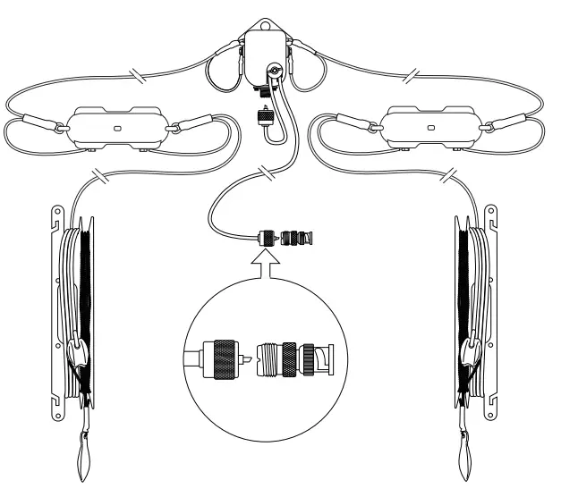 BCM209203/05
© Barrett Communications
Introduction
The Barrett Rapid Deployment Broadband Dipole Antenna is a dipole antenna with loading to allow broadband operation. It will operate continuously across the band from 2-30 MHz. The power rating is 150 W PEP. Throwing cords are provided that can be used to elevate the antenna or to secure it to the ground. The antenna can be used in a number of configurations (see over), depending on the structures available for elevation. Compatible Barrett masts include 10m Rapid Deployment Mast (P/N 2090-02-21), 10m Rapid Deployment Composite Mast (P/N 2090-02-24), and 5m Rapid Deployment Mast
(P/N 2090-02-04). This antenna is most suitable for HF radio manpack and temporary base station deployment. This guide will indicate the recommended deployment type for each configuration with these symbols. Contents Overview
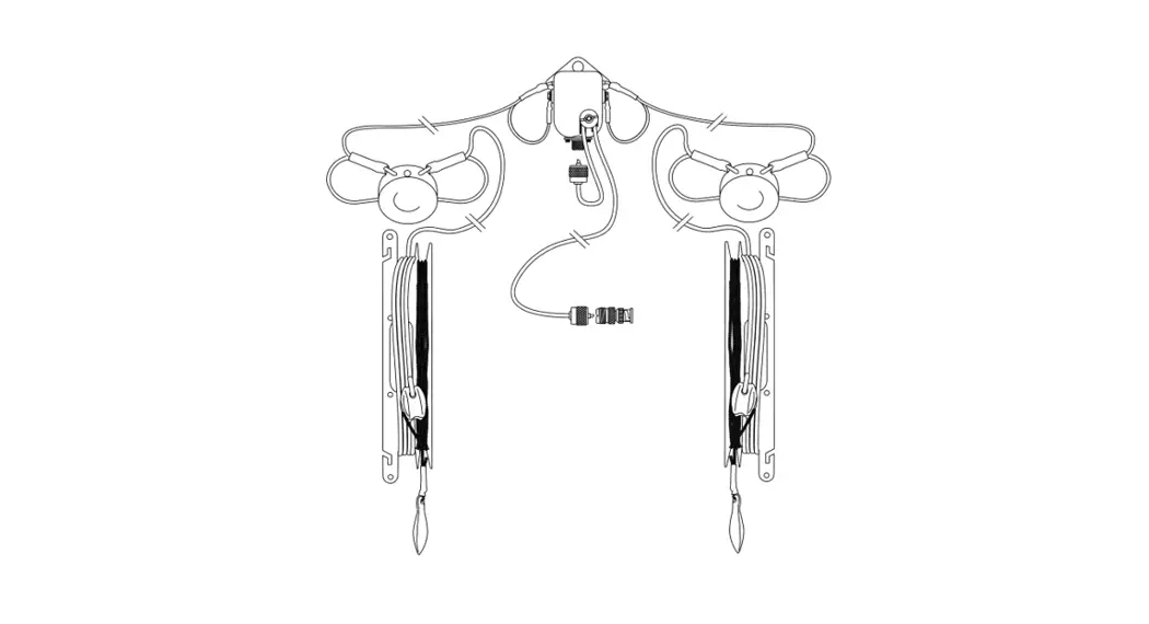
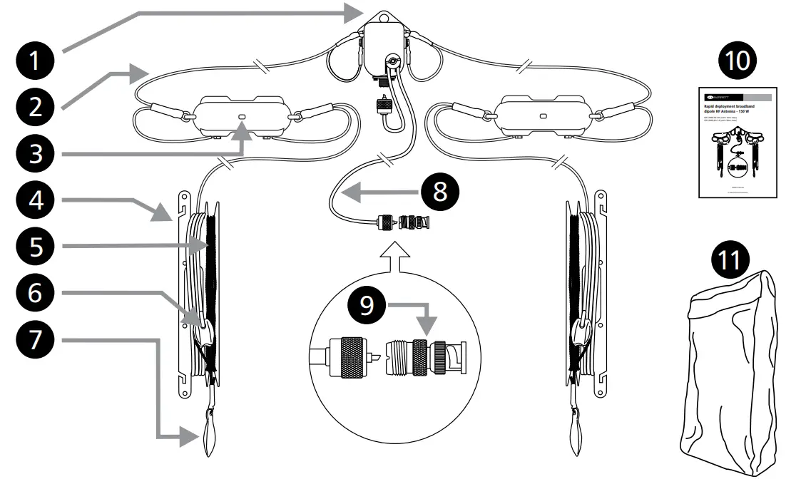
- Balun
- 2 x Kevlar core antenna wire
- 2 x Loads, knotted
- 2 x large winders
- 2 x 10m Throwing cord
- 2 x Insulators
- 2 x Throw weights
- RG-58 coax
- UHF to BNC adaptor
- Instruction sheet
- Carry bag
Horizontal Configuration
Horizontal configuration has a maximum gain on the broadsides of the antenna and reduced gain along the axis. Therefore, the broadsides should point in the direction of the receiving stations, if possible. Antenna height above ground affects radiation angle. Lower heights give higher radiation angles which is better for NVIS (shorter distance) operation. Greater heights give a lower radiation angle, which is favorable for longer distance communication.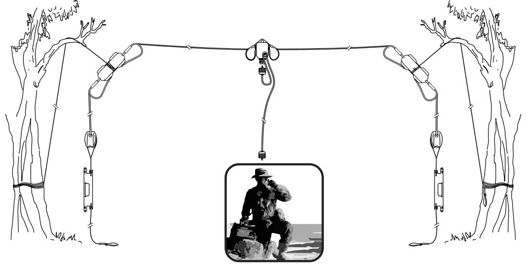
Inverted V Configuration
The inverted-V configuration has a more Omnidirectional pattern than the horizontal configuration, with lower maximum gain. The ends of the antenna should be at least 0.5m above ground. Suitable mainly for NVIS and medium-distance communication.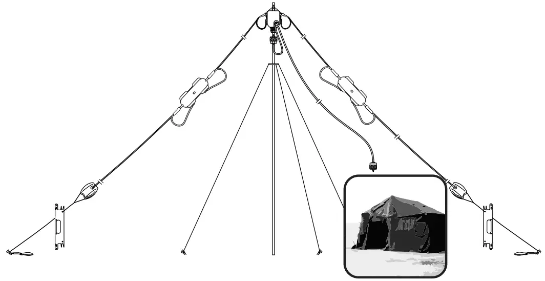
Sloping Configuration
Radiation with the Sloping configuration becomes more directional, with increased gain in the direction of the lower end of the antenna, and reduced gain towards the higher end.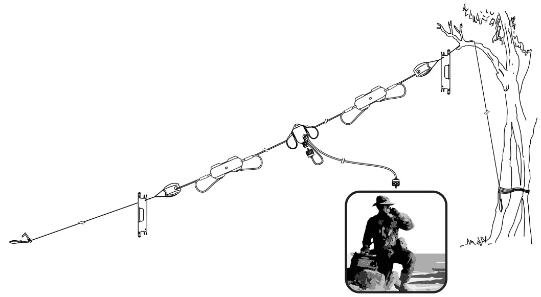
Inverted U Configuration
The inverted U configuration has a radiation pattern between that of a horizontal configuration and an inverted V configuration. For optimum performance, the radiating elements should be fully unwound, and should not touch the ground. Suitable for NVIS to medium distance. Longer distance performance will be enhanced by erecting the antenna at a height of 10m or more.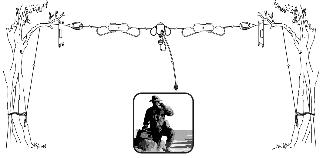
Radiation Pattern (Horizontal Configuration 8m height)
Vertical Plane – Total Gain (dBi)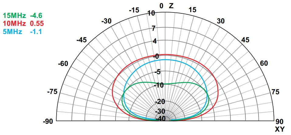
Horizontal Plane – Total Gain (dBi) 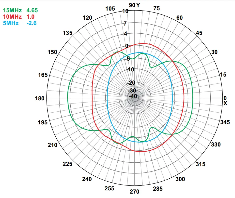
Radiation Pattern (Inverted V Configuration 8m height)
Vertical Plane – Total Gain (dBi) 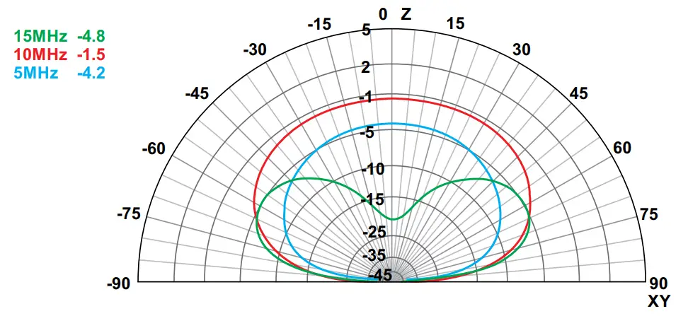
Horizontal Plane – Total Gain (dBi) 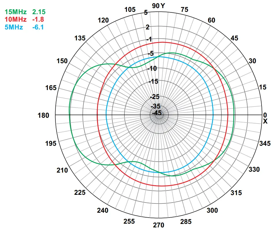
Specifications
Electrical
| Frequency Range | 2 – 30 MHz |
| Input Impedance | 50 ohms |
| Power Rating | 150 W PEP |
| Connector | UHF female with BNC adaptor |
| Polarisation | Horizontal |
| Radiation Pattern | Essentially Omni-Directional (when mounted as an inverted V) |
Mechanical
| Material | Kevlar core, copper braid, PVC sheath, UV Stabilized Re-inforced Nylon housings |
| Length | 48m |
| Weight | 1.2kg |
| Packed size | 37cm x 18cm x 5cm |
| Colour | Radiating wire elements – NATO green Balun housing – black |
Environmental
| Wind | 160 km / hour survival, 120 km / hour operational |
| Temperature | -40° C to +70° C operational -40° C to +85° C storage |
| Humidity | 0% to 97% relative humidity |
| Ingress Protection | To IP67 (dust and water) |
Specifications are typical. Equipment descriptions and specifications are subject to change without notice or obligation


