hy-gain V3R VHF Antenna
General Description
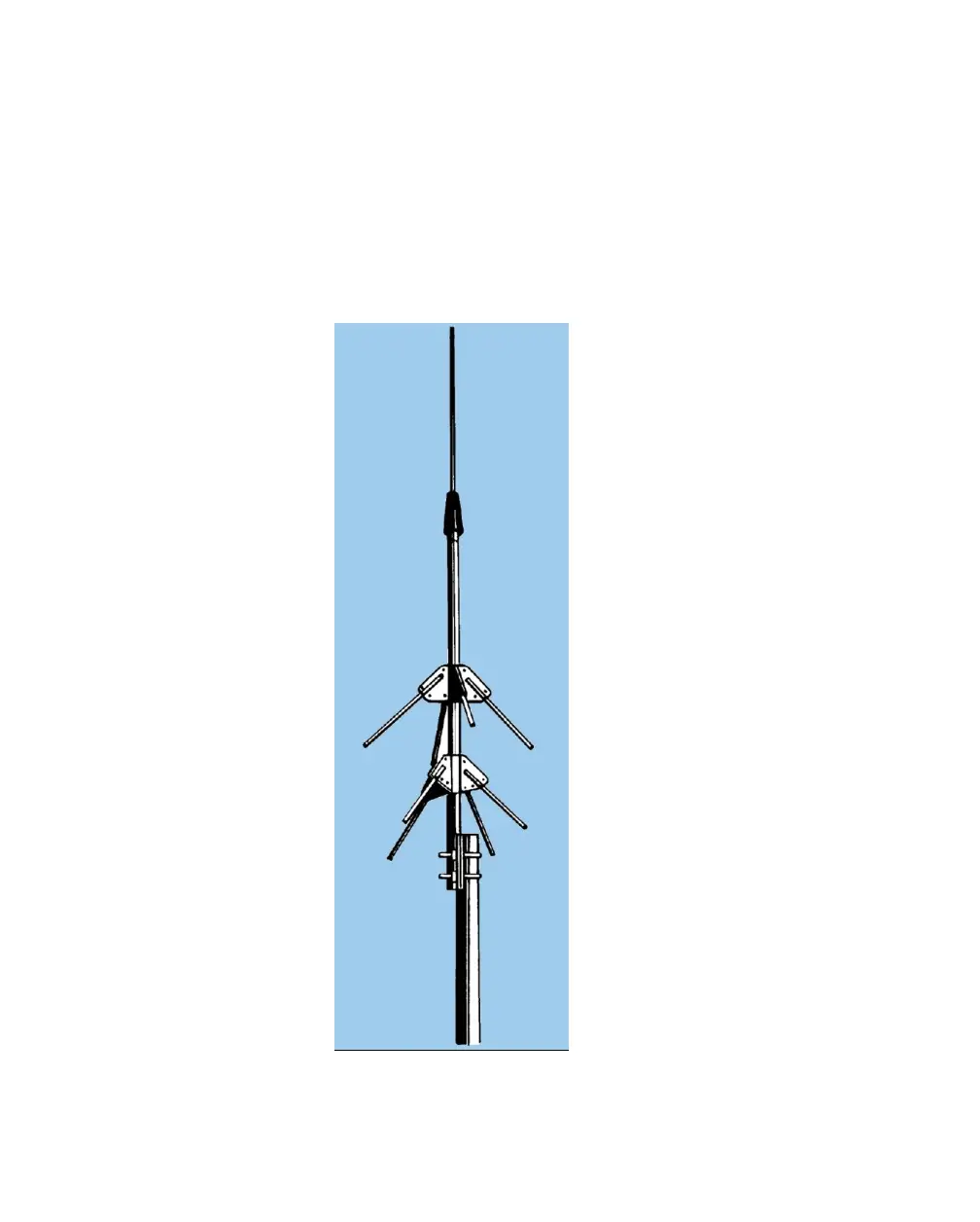
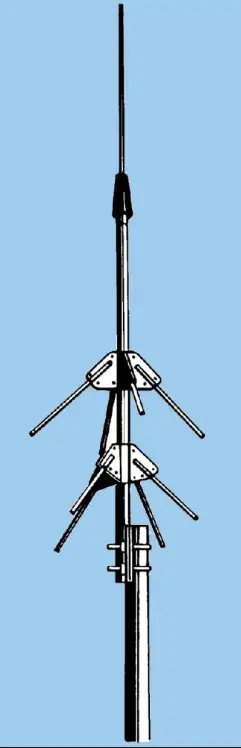
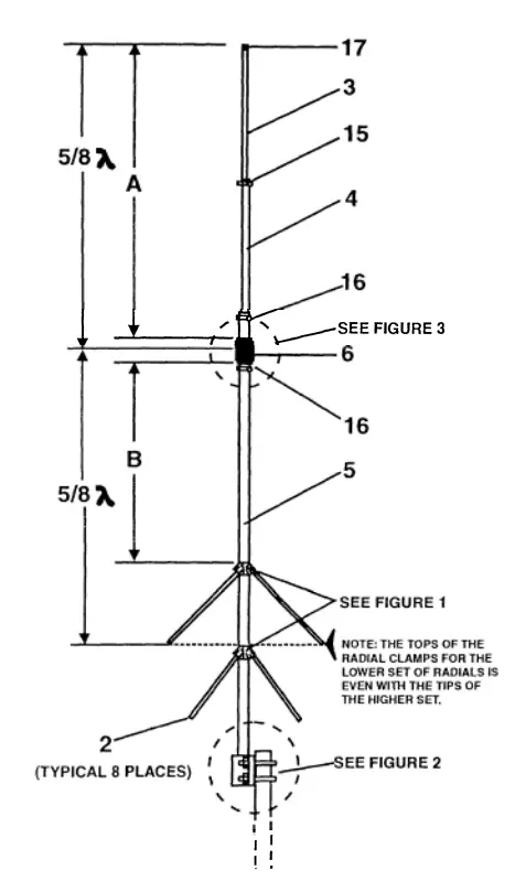
The new Hy-Gain V3R VHF antenna is a collinear 5/8-wave omnidirectional vertical antenna for the 216-225 MHz frequency range.
The V3R features two sets of 1/4-wave radials which properly decouple the lower 5/8-wave radiator from the mast. It also features a 500 watt enclosed coil that matches the antenna to a nominal 50 ohms.
The feed point is a female UHF connector that is protected from the weather within the lower radiator. The V3R also features a mast-to-mast bracket that will accept up to a 2 inch O.D. mast.
Settings are supplied so that the antenna can be set to any frequency between 215 and 23 0 MHz.
SPECIFICATIONS
VSWR at Resonance … less than 1.5:1
2:1 VSWR Band Width …. 12 MHz minimum
Power Gain…… 3 dBd (5.2dBi)
Antenna/ Masclslation…. 20dB
Power Input… 500 watts continuous
Lighting Protection.. DC ground
Height Protraction….. 6 feet 9.5 inches ( 2.1m)
Wind Area…. 0.5 sq .st. inches ( 2.1m)
Maximum Mast O.D…… 2 inches ( 51 mm)
Hardware….. 18 – 8 stainless steel
Maximum Wind Survival ( Without ice)… 100 mph ( 161 kmph )9
Net Weight….. 5 ibs ( 2.2 kg )
Assembly
Unpack the antenna and check the parts against
Select four of the radial clamps and associated hardware and loosely assemble them as shown in Figure 1.
Repeat the previous step for the remaining four radial clamps.
Set both assembled clamps upside down on a flat surface.
Select the eight (8) 7/16″ x 12″ radial tubes (Item No. 2), and insert them completely into theassembled radial clamps.
Tighten the outer eight (8) screws of each assembly just enough to hold the radial tubes in place. These screws will be securely tightened in a later step.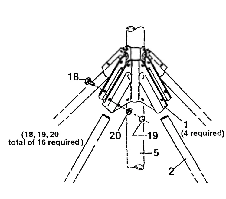
Item
| No. | Description |
| 1 | Radial Clamp , 45 degrees |
| 2 | Tube 7/16″ * 12 |
| 5 | Tube , 1 ” O.D * 48 ” , slotted |
| 18 | Bolt , # 10-24 * 1/2 , hex head |
| 19 | Nut, # 10-24 ,hex |
| 20 | lock washer, #10 , Internal |
Select the l” x 48″ tube (Item. No. 5).
Slip both radial assemblies over the top of the 48″ tube and position as shown in Figure 4 and Detail A. The slotted end of the 48″ tube is the top. Determine the “B” dimension from Table 1. For example, at 221 MHz, B= 16 1/2″ (419 mm).
Tighten all screws in both radial assemblies securely and evenly.
Select the mast-to-mast clamps and associated hardware and loosely assemble them as shown in Figure 2. Install the 1/4″ hardware first.
Slide the assembled mast-to-mast clamp over the bottom end of the 48″ tube as shown in Figure 2 and securely tighten the four (4) 1/4″-20 x 3/4″ bolts, nuts and lock washers (Item Nos. 8, 11 and 13).
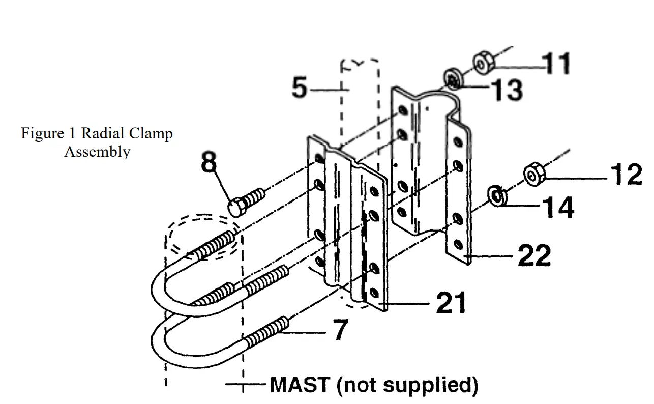
Item
| No. | Description |
| 5 | Tube, I” 0.0. x 48″ |
| 7 | U-Bolt, 5/16″-18 |
| 8 | Bolt, l/4″-20 x 3/4″, hex head |
| 11 | Nut., l/4″-20, hex |
| 12 | Nut, 5/16″-18, hex |
| 13 | Lockwasher, I /4″, internal |
| 14 | Lockwasher, 5/16″, split |
| 21 | Mast-to-mast bracket plate 1 1/8″” |
| 22 | Mast -to-ma.~t bracket clamp, I 1/8′” |
UPPER RAD IA TOR/COIL ASSEMBLY
Refer to Figure 3.
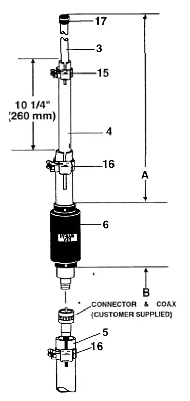
| Item# | Description |
| 3 | Tube, 5/8″ x 15″ |
| 4 | Tube, 7/8″ x 15″ swaged &slotted |
| 5 | tube, 1″ 0.0. x 48″ slotted |
| 6 | Coil, V3R |
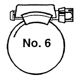
| 15 | Clamp, #6, Tubin |
| 16 | Clamp, #10, Tubing |
| 17 | Caplug,5/8″ |
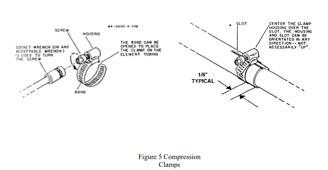
Select the V3R Coil Assembly. The coaxial cable wili attach to this in a later steo. Select one No. 10 compression clamp (Item 16) and install over the slotted tube end of the coil assemhlv (Ttem 6).
Select the 7/8″ O.D. x 15″ tube (Item 4) and insert the plain end into the slotted tube of the coil assembly 4 3/4 inches. Position the compression clamp as shown in Figure 5 and tighten securely.
Select one No. 6 compression clamp (Item 15) and place over the swaged/slotted end of the 7 /8″ tube (Item 4) .
Select the 5/8″ x 15″ (Item 3) tube and insert either end into the 7/8″ tube (Item 4). Refer to Figure 4. Adjust the 5/8″ x 15″ tube so dimension “A” is set for the frequency of operation. For example, at 221 MHz, A= 27 1/4″ (692 mm) See Table I. Tighten the No. 6 compression clamp (Item 15) securely. NOTE: The tuning charts in this manual are accurate. However, due to variation in installations some minor adjustments may be required to resonate the antenna on the desired frequency.
Select the 5/8″ caplug (Item No. 17) and slip it over the end of the 5/8″ tube.
NOTE: Dimension “A” is from the top of the coil form to the tip of the element. Dimension “B” is from the bottom of the coil form to the top of the radial clamps.
| FREQUENCY | “A” | “B” |
| 215 | 28 1/2″ | 17 3/4″ |
| 221 | 271/4″ | 161 /2″ |
| 223 | 26 3/4″ | 16″ |
| 225 | 261/4″ | 151 /2″ |
| 230 | 25 1/2″ | 14 3/4″ |
Item
| No. | Description |
| 3 | Tube, 5/8″ x 15″ |
| 4 | Tube, 7/8″ x 15″ swaged & slotted |
| 5 | Tube, I” O.D. x 48″ slotted |
| 6 | Coil VIR |
| 15 | Clamp #6 Tubing |
| 16 | Clamp #10 Tubing |
| 17 | Caplug , 5/8″ , black |
Select the proper size tube clamp as shown in Figure 5. When installing the clamps, place the clamp near the tube end with the top of the clamp over the slot in the tube as shown.
After adjustment of the tubing lengths, tighten the clamp with a 5/16 inch nut driver, socket, or open end wrench until the tubing will not twist or telescope.
| No. | Description | Fits |
| 358756 | Clamp, Size #6 | Sizes |
| all stainless steel 5/16″ hex head screw | 1/2″ and 3/4″ |
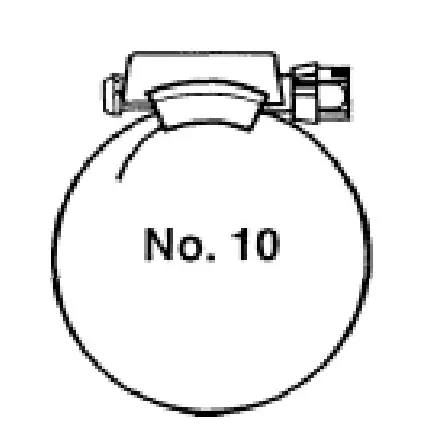
| Part No. | Description | Fits |
| 358757 | Clamp, Size #10 | Tubing Sizes |
| all stainless steel 5/16″ hex head screw | 1” |
Select the No. 10 tube clamp and slip it over the top end of the l II x 48 11 tube. Position it as shown in Figure 3 and tighten it just enough to prevent it from sliding down the tube.
INSTALLATION
There are two ways to attach your coax to the V3R antenna. The first method involves attaching a short length of coax to the antenna before attaching the antenna to the supporting mast.
The remaining length of coax can then be attached and routed to the radio. The short length of coax must be at least 6 feet long, so the connection between coax lengths can be made below the mast-to-mast bracket.
The second method involves attaching the complete length of coax to the antenna before attaching the antenna to the supporting mast. In this method, the antenna and entire coax length must be carried up the tower or mast.
Choose one of the suggested methods of attaching the coax to the V3R.
Insert one end of the coax into the bottom of the l II x 48 11 tube. Push the coax through until the connector emerQ”es from the ton of the tuhe.
Screw the coax connector onto the V3R coil connector.
Push the coax cable into the top of the l II x 48 11 tube until the matching coil rests on the one inch tube. Tighten the No. 10 tube clamp.
The antenna can now be mounted on a mast (2 11 O.D. max.). For adequate lightning protection, the antenna supporting structure must be well grounded.
WARNING
Installation of this product near power lines is dangerous. For your safety, follow the installation directions.
Several antennas may be mounted on the same mast. Your V3R should be mounted above the other antenna for best performance. When side mounting the V3R on a tower, it should be kept at least 20 inches away from the tower. The ideal distance to acheive ‘a near omni-directional radiation pattern is approximately 27 inches from the nearest tower leg or face
V3R Parts List
| Item No. | Part No. | Description Qty | |
| 1 | 160012 | Radial Clamp, 45 degree | 8 |
| 2 | 170476 | Tube, 7/16″ O.D. x 1211 | 8 |
| 3 | 170615 | Tube, 5/8″ O.D. x 15″ | 1 |
| 4 | 190212 | Tube, 7/8″ O.D. x 15″ swaged | 1 |
| 5 | 191005 | Tube Assembly, l” x 4811 | 1 |
| 6 | 878706 | Coil Assembly, V3R | 1 |
| 878631 | Parts Pack V3 | 1 | |
| 7 | 540036 | U-Bolt, 5/16″-18 | |
| 8 | 505266 | Bolt, 1/4″-20 x 3/4″ hex head | |
| 9 | (Not Used) | ||
| 10 | (Not Used) | ||
| 11 | 554099 | Nut, l /4″-20, hex | 5 |
| 12 | 555747 | Nut, 5/ 16″-18 hex | 5 |
| 13 | 562961 | Lockwasher, 1/4″ internal | 5 |
| 14 | 564792 | Lockwasher, 5/16″ split | 4 |
| 15 | 358756 | Clamp, size #6 tube | 1 |
| 16 | 358757 | Clamp, size #10 tube | 2 |
| 17 | 450503 | Caplug, 5/8″ black | 1 |
| 18 | 500158 | Bolt, #10-24 x 1/2″ hex head | 33 |
| 19 | 554071 | Nut, #10-24 hex | 33 |
| 20 | 565697 | Lockwasher, #10 internal | 33 |
| 21 | 160011 | Mast-to-Mast Pla | 1 |
| 22 | 160047 | Mast-to-Mast Clamp | 1 |
NOTE: Some extra small parts are included for snares.
Converting American Measurements to Metric Use this scale to identify lengths of bolts, diameter of tubes, etc. The American inch (1 “) and foot ( l ‘) can be converted to centimeters in this way.
1 inch (I”)= 2.54 cm
1 foot (1 ‘) = 30.48
Example: