
DOMETIC GP-ISW-R Pure Sine Wave Inverter Remote
FEATURES
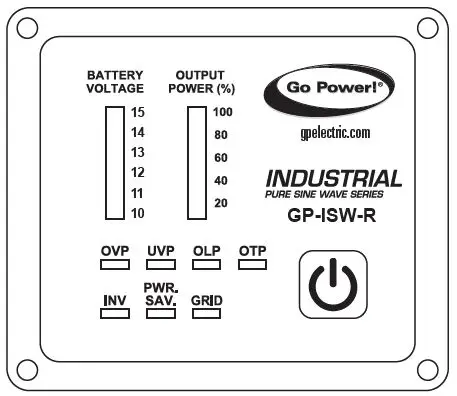
The GP-ISW-R remote allows the switching on and off of any GP-ISW inverter from a remote location. The LED display indicates the following:
- Battery bank voltage display
- Output power display
- Error condition indicator (High Battery, Low Battery, Over Temperature, Over Load conditions)
- Action condition indicator (INV, POWER SAVING, GRID)
SPECIFICATIONS
| SPECIFICATION ITEM | GP-ISW-R-12/24 |
| Input Voltage | 10.5 ~ 66VDC |
| Operating Temperature Range | 0 ~ 40°C |
| Storage Temperature Range | -30°C ~ 70°C |
| Standby Current Draw | < 80mA |
| Compatible Inverters | GP-ISW700/1000/1500/2000/3000/4000 |
INTRODUCTION
FRONT PANEL INTRODUCTION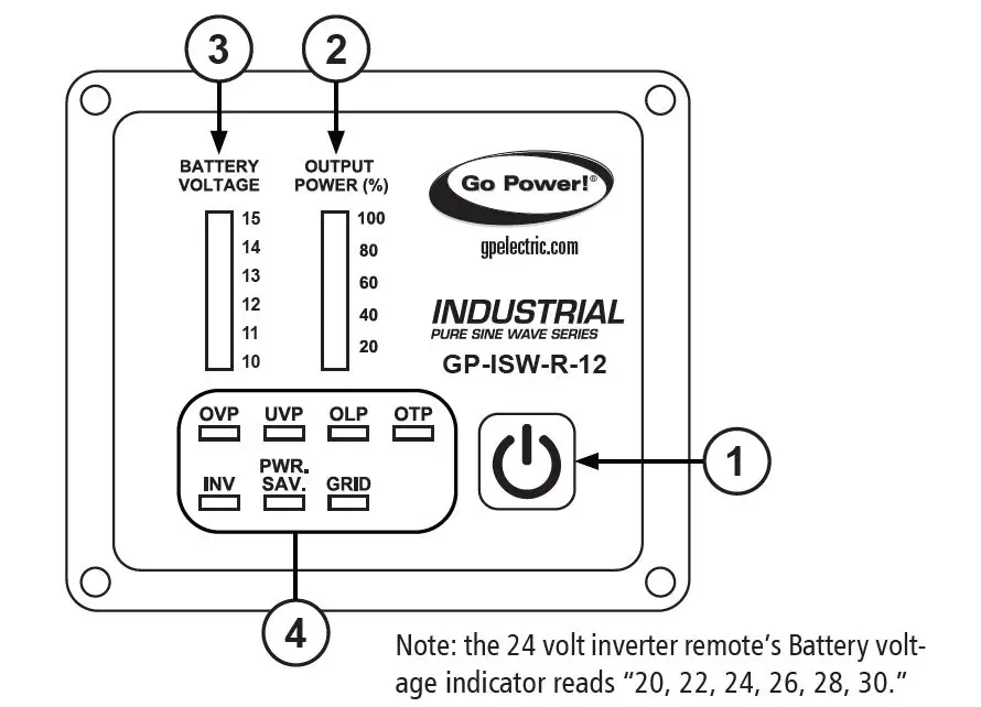
Note: the 24 volt inverter remote’s Battery volt-age indicator reads “20, 22, 24, 26, 28, 30.”
- Power ON/OFF button
- Power ON/OFF button turns the inverter on or off.
- Output power indicator
- Output power indicator shows the power draw from the inverter by the load. Ideally, the output power indicator should remain in the green & orange area of the bar chart. If the output power indicator is up to the red area, the OLP LED will flash and the inverter will shut down.
- Battery voltage indicator
- The battery voltage indicator will move up and down as the battery voltage changes. Ideally, the voltage should remain in the green area of the bar chart.
If the voltage goes into the red area at the top and bottom of the bar chart, the inverter may shut down.
- The battery voltage indicator will move up and down as the battery voltage changes. Ideally, the voltage should remain in the green area of the bar chart.
- Other indicators
- OVP (Over voltage protection):
- This indicates that the inverter will shut down because its input voltage is above the voltage limit.
- UVP (Under voltage protection):
- This indicates that the inverter will shut down because its input voltage is below the voltage minimum.
- OLP (Overload protection indicator):
- Indicates the inverter will shut down due to a short circuit or overload protection.
- OTP (Over temperature protection indicator):
- Indicates the inverter will shut down due to over-temperature protection. Once the inverter cools down, the indicator will turn off automatically.
- INV indicator:
- Indicates the inverter is ready.
- PWR. SAV. indicator:
- Power-saving functions are described below:
LED MEANING INVERTER OUTPUT Solid Ready ON Flashing Active OFF Off Inactive - GRID indicator:
Indicates the AC Grid is connected to the inverter (only functional when connecting inverter series with Transfer Relay).
INTRODUCTION
REAR PANEL INTRODUCTION 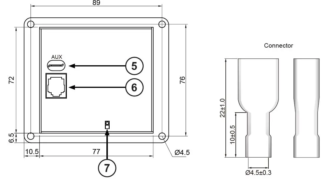
- AUX port
Note: the AUX port is only used in work trucks.
The connector (shown above) attached to AUX wire (AWG 14 or 16) must be connected with a 12V / 0.5A fuse.- Ignition Lockout function:
Turns OFF the inverter when the auxiliary input wiring is connected to the ACC with 12 volts. - Return Override function:
Turns ON the inverter when the auxiliary input wiring is connected to the reversed gear shift with 12 volts.
- Ignition Lockout function:
- JP1
The JP1 is to set either the Return Override function or the Ignition Lockout function.- JP1 jumper “Short” – Return Override function:
- Turns ON the inverter when the auxiliary input wiring is connected to the reversed gear shift with 12 volts.
- JP1 jumper “Open” – Ignition Lockout function:
- Turns OFF the inverter when the auxiliary input wiring is connected to the ACC with 12 volts.
- The connector which is connected to AUX power must be used with a 12V / 0.5A fuse.
TRIGGERED SIGNAL JP1
INVERTER STATUS
AUX 1 Open OFF 0 Open ON 1 Short ON 0 Short OFF Note: default mode is Open.
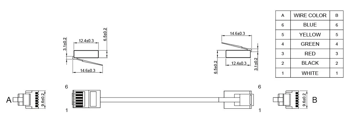
- PHONE JACK CONNECTOR
1. Before connecting, make sure to switch the inverter to REMOTE mode.
WARNING! DO NOT use a standard telephone cable.
© 2021 Go Power!
Worldwide Technical Support and Product Information gpelectric.com Go Power! | Dometic
201-710 Redbrick Street Victoria, BC, V8T 5J3
Tel: 1.866.247.6527
80325_MANUAL_ISW-R_RevB


