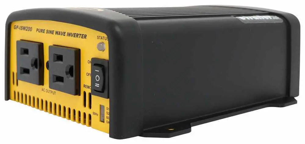
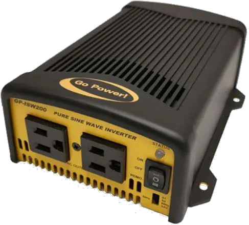
Go Power GP-ISW-200 Pure Sine Wave Inverter
Quick Start Guide
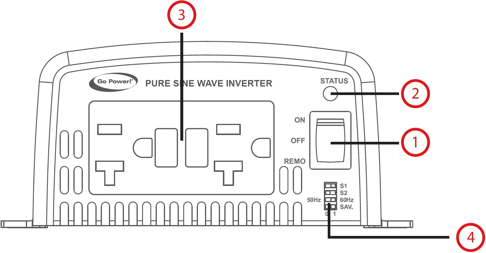
- ON / OFF / Remote Main Switch
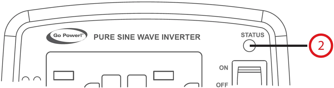
- LED Indicator
- AC Output
- Function Switch
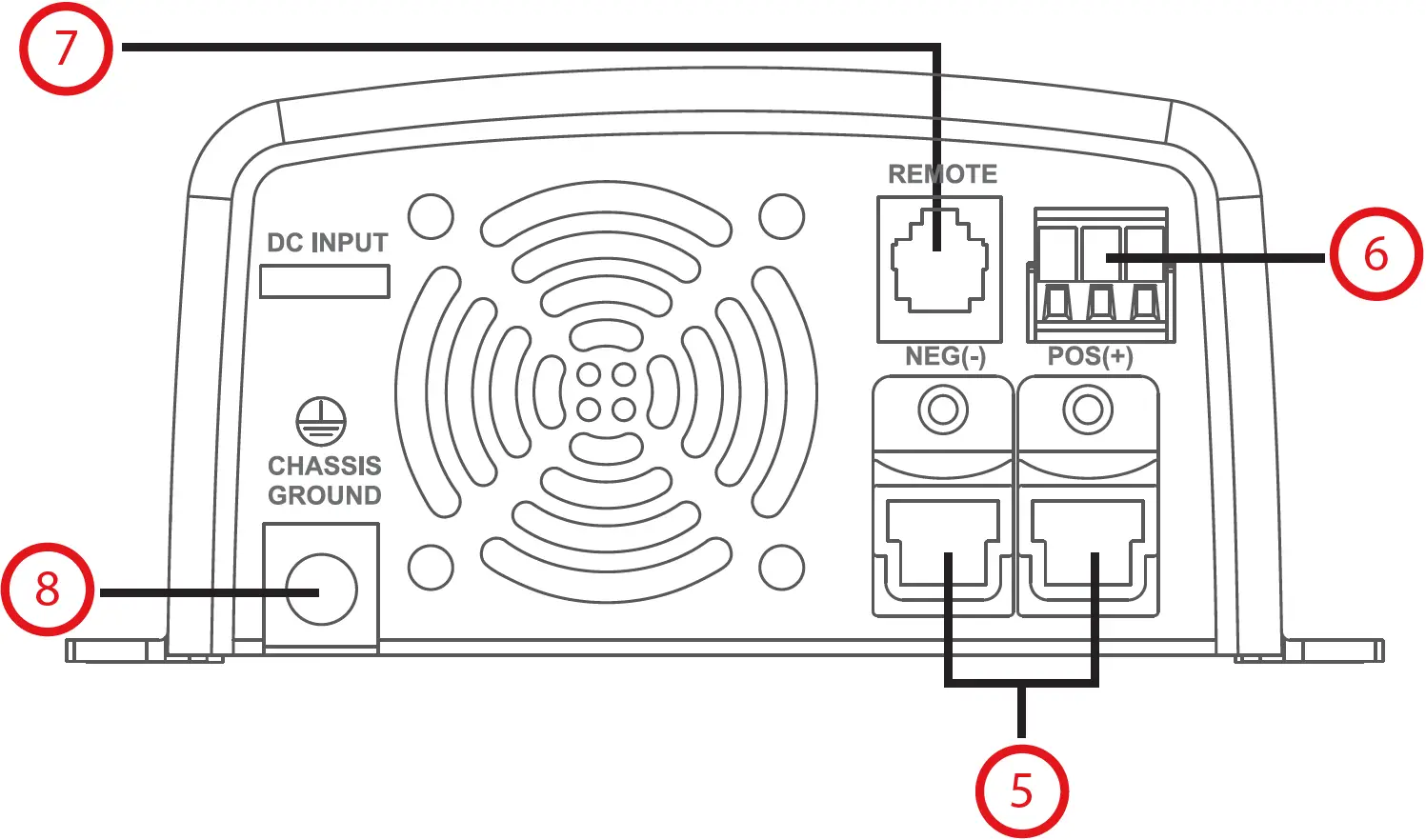
- DC Input Terminal
- Green Terminal
- Remote Port (RJ-11)
- Chassis Ground
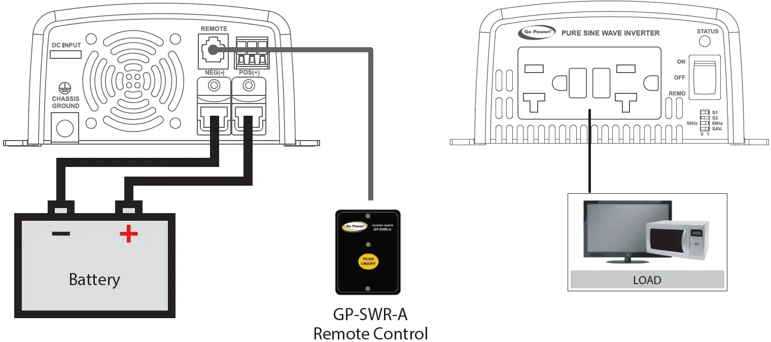
Installation and Wiring – Overview
The GP-ISW should be located as close to the batteries as possible but not within the same compartment. The length and size of the DC Cables will affect performance. Long DC wires tend to lose efficiency and reduce the overall performance of the Inverter/Charger.
For optimum Inverter performance the GP-ISW must be installed so the front and rear air vents are not blocked or obstructed in any way. Do not install the GP-ISW in an area with limited air flow. Allow as much space around the Inverter as possible, leaving at least 4 inches of airspace clearance around all ventilation areas.
Tools and Materials Needed
- Flathead Screwdriver (for wire terminals)
- Philips Screwdriver (for mounting screws)
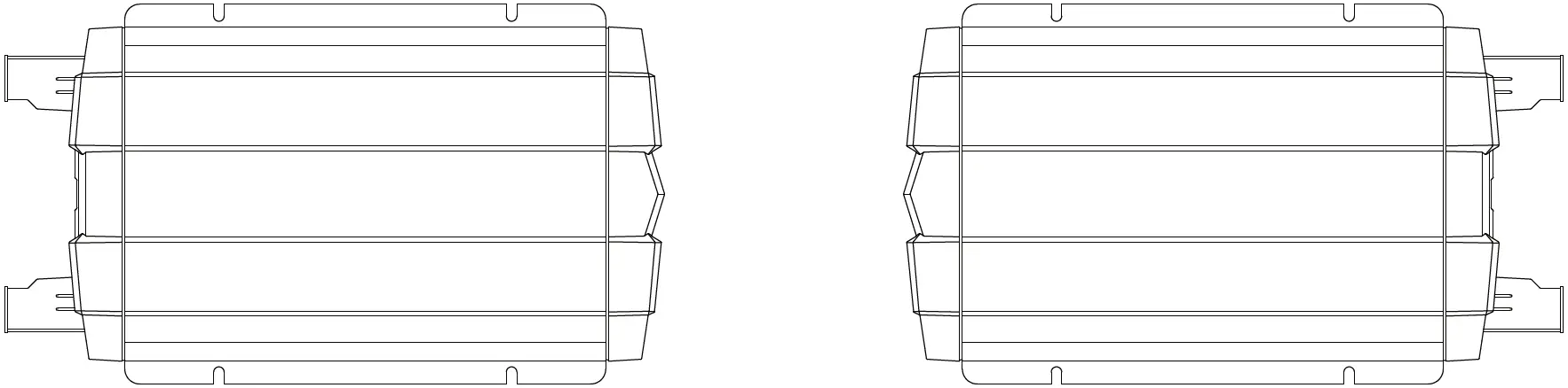
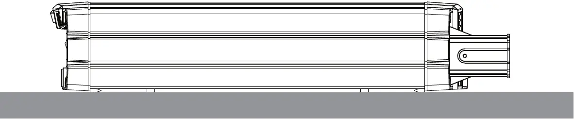
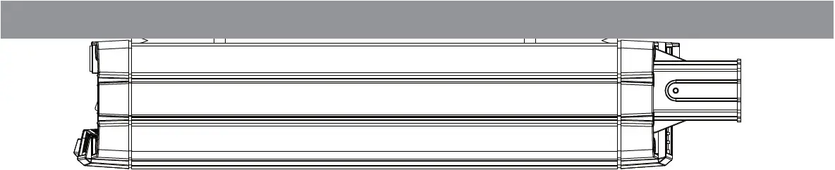
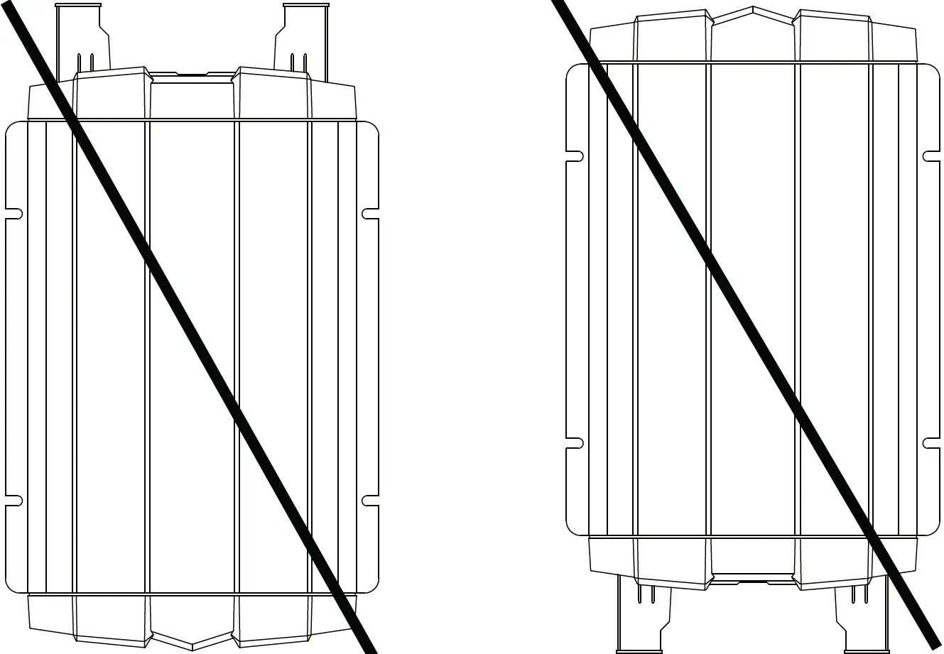
Mounting Orientations
- HORIZONTAL WALL MOUNT, BASE DOWN

- HORIZONTAL MOUNT, BASE UP

- HORIZONTAL MOUNT, BASE DOWN

- VERTICAL MOUNT, DO NOT MOUNT THE GP-ISW IN THIS CONFIGURATION

LED Indicators
Input Voltage Level
| LED Status | DC 12V | DC 24V |
| Red | < 11.0V | < 22.0V |
| Orange | 11.0 ~ 11.5V | 22.0 ~ 23.0V |
| Green | 11.5 ~ 15.0V | 23.0 ~ 30.0V |
| Orange | 15.0 ~ 15.5V | 30.0 ~ 31.0V |
| Red | < 15.5V | > 31.0V |
Input Voltage Level
| LED Status | Status | Recovery Point |
| Green | Normal | |
| Red | Over Current Protection/ Over Load Protection (AC output short-circuit and over load) | |
| Red Blink | Under Voltage Protection/ (Input DC voltage under spec) | 12.5V @ DC12V System 25V @ DC24V System |
| Red Fast Blink | Over Voltage Protection (Input DC voltage over spec) | 14.5V @ DC12V System 29V @ DC24V System |
| Orange | Device startup process abnormal | – |
| Orange Fast Blink | Under Temperature Protection/ (Heat sink temp. under -20°C) | > 0°C (Heat sink temperature) |
| Orange Slow Blink | Over Temperature Protection (Heat sink temp. over 80°C) | < 60°C (Heat sink temperature) |
Specifications
| Note: Both 12V and 24V inverter specifications are listed below. | ||
| GP-ISW200 | GP-ISW400 | |
| Continuous Output Power | 200 W (VA) | 400 W (VA) |
| Maximum Surge Rating | 250 W (VA) | 800 W (VA) |
| Output Waveform | Pure Sine Wave | |
| Output Voltage Range ± 3% | 100 – 120 VAC (Dip Switch Selectable) | |
| Input Voltage | 12 V: 10 – 16 VDC | |
| Efficiency | 12 V: 89% 24 V: 91% | 12 V:88% 24 V: 89% |
| No Load Current Draw / Powersave | 12 V: <0.5A 24 V: <0.4A | 12 V: <1A @ 12VDC 24 V: <0.5 @ 24VDC |
| Input Protection | Reverse Polarity (Fuse) / Under Voltage / Over Voltage | |
| Output Protection | Short Circuit / Overload / Over Temperature | |
| Low Battery Alarm ± 0.3 V (± 0.5 V for 24 V inverters) | 12 V: 10 V 24 V: 21 V | |
| Low Battery Shutdown ± 0.3 V (± 0.5 V for 24 V inverters) | 12 V: 10 V 24 V: 20 V | |
| Operating Temperature Range | -4°F – 140°F (-20°C – 60°C) | |
| Storage Temperature Range | -22°F – 158°F (-30°C – 70°C) | |
| Cooling | Temperature and Load Controller Cooling Fan | |
| AC Output Connections | Dual GFCI Outlet | |
| Dimensions (W x H x L) | 5.91 x 2.68 x 7.36 inch (150 x 68 x 187 mm) | 5.91 x 2.68 x 7.36 inch (150 x 68 x 187 mm) |
| Weight | 3.5 lbs (1.6 kg) | 3.5 lbs (1.6 kg) |
| Warranty | 2 Years | |
| Inverter Install Kits | GP-DC-KIT1 | |
| Remotes (Optional) | GP-ISW-R / GP-SWR-A | |
| Regulations and Safety | EMC / Certified FCC Class B | EMC / Certified FCC Class B / Certified UL 458 |
See user manual for complete instructions at gpelectric.com


