![]() VG0891
VG0891
Revision: B2
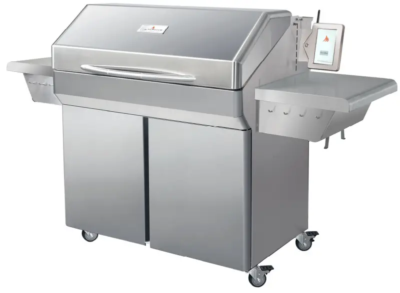
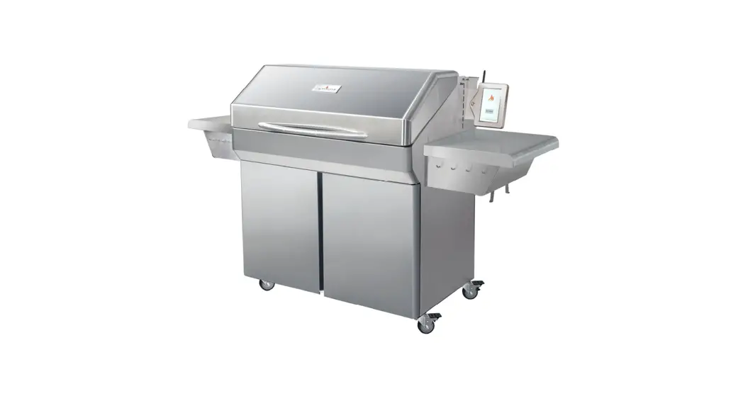
Memphis Elite Cart ITC 3
IntelliBurn Technology®
Model Number VG0002S
VG0891 Elite Cart ITC3 Wood Fire Grills
Read all instructions before installing and using this appliance. Save these instructions for future reference.
A MAJOR CAUSE OF FIRES IS FAILURE TO MAINTAIN REQUIRED CLEARANCES (AIR SPACES) TO COMBUSTIBLE MATERIALS. IT IS OF UTMOST IMPORTANCE THAT THIS PRODUCT BE INSTALLED ONLY IN ACCORDANCE WITH THESE INSTRUCTIONS.
 https://memphisgrills.com/support-resources/warranty-registration/
Stop!
Scan the QR Code above now to secure your grill warranty registration.
Or register online at:
https://memphisgrills.com/support-resources/warranty-registration/
Clearance to Combustible Materials
YOUR MEMPHIS GRILL MUST MAINTAIN THE SPECIFIED CLEARANCE TO COMBUSTIBLE MATERIALS WHILE OPERATING THE GRILL OR WHILE THE GRILL IS HOT! Combustible Material is wood, dry wall, siding or any other material that has to ability to catch fire.
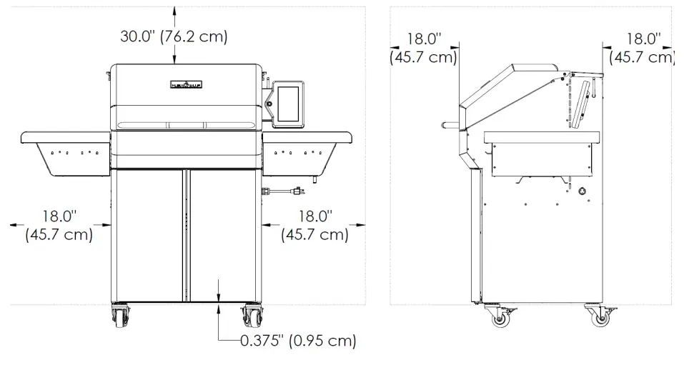
Below are some guidelines to ensure safe operation of your Memphis Grill
- The grill is to be supported by the casters provided.
- Grill casters are to be locked while the grill is in use or while the grill is hot.
- It is recommended that the grill be placed on a non-combustible surface.
- Operating the grill under a combustible ceiling or overhang is NOT recommended.
- Maintain the minimum clearance to combustible materials specified above.
A major cause of fires is failure to maintain required clearances (air spaces) to combustible materials. It is of the utmost importance that this product be installed only in accordance with these instructions.
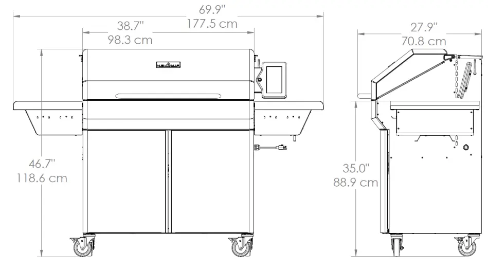
Grill Dimensions
Other Grill Information
| Main Grate Area– 37.1 in X 17.4 in. | [94.3 cm X 44cm] | 644 in. sq. | [4,149 cm sq.] |
| Top Grate Area– 37.1 in. X 5.5 in | [94.3 cm X 14 cm] | 204 in. sq. | [1,320 cm sq.] |
| Optional Middle Grate Kit Area– 37.1 in. X 11 in | [94.3 cm X 28 cm] | 408 in. sq. | [2,640 cm sq.] |
Grill Height with Hood Open– 66.2 in. [168 cm]
Grill Width with Slides Shelves Open– 91.9 in. [233 cm]
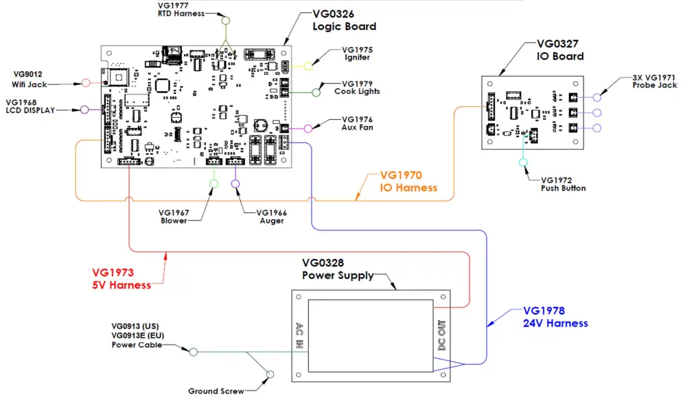
Memphis Controller Diagram
| Part Number | Name | Description |
| VG1966 | Auger Wiring Harness | 5 pin connector from auger motor to the logic board |
| VG1967 | Blower Wiring Harness | 4 pin connector from blower to the logic board |
| VG1968 | Display Wiring Harness | 9 pin connector from the LCD display to the logic board |
| VG0913(E) | US Power Cable (Euro) | Power cable that plugs into 120VAC (US) or 240VAC (EU) wall outlet |
| VG1970 | IO Wiring Harness | 8 pin connector from IO board to the logic board |
| VG1971 | Probe Jack Wiring Harness | 2 pin connector from meat probe jack to the IO board |
| VG1972 | Push Button Wiring Harness | 4 pin connector from push button in the Display Housing to the IO board |
| VG1973 | 5V Wiring Harness | 5 pin connector from power supply board to the logic board |
| VG1975 | Igniter Wiring Harness | 2 pin connector from igniter to the logic board |
| VG1976 | Auxiliary Fan Wiring Harness | 2 pin connector from Aux fan to logic board |
| VG1977 | RTD Wiring Harness | 2 Pin connector from RTD to the logic board. Connection to board is non-polarized |
| VG1978 | 24V Wiring Harness | 2 pin connector from power supply to logic board. Provides power to blower, aux fan, auger motor, cook lights and LCD |
| VG1979 | Cook Light Wiring Harness | 2 pin connector from cook lights to logic board |
| VG9012 | Wifi Jack | Single conductor jack installed in right panel connected to the logic board |
| VG0326 | Logic Board | Controls components related to smoking and cooking |
| VG0327 | IO Board | Controls push button and meat probe jacks |
| VG0328 | Power Supply Board | Provides 24V DC and 5V DC power |
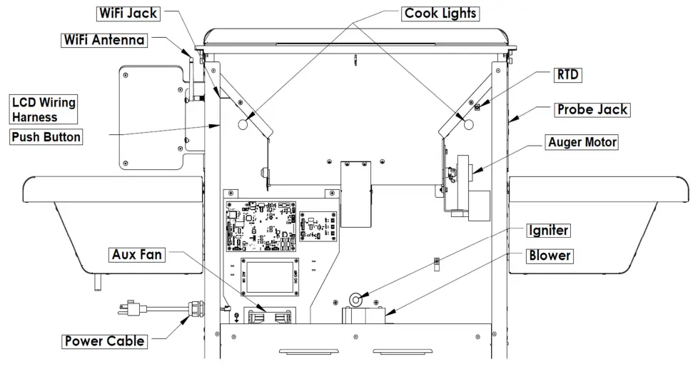
| Part Number | Name | Description |
| VG9501 | Auger Motor | This component rotates the auger to supply fuel into the burn pot |
| VG1967 | Blower | This component pulls air from the lower cabinet and into the firebox for combustion |
| VG1968 | LCD Wiring Harness | Used to display Grill information and change grill settings |
| VG0913(E) | US Power Cable (Euro) | Power cable that plugs into 120VAC (US) or 240VAC (EU) wall outlet |
| VG1971 | Probe Jack | This component is used to plug probes for monitoring meat temperature |
| VG1972 | Push Button | This component is used to set the grill to cooldown, reset the controller, or put the display to sleep |
| VG1975 | Igniter | This component provide the initial heat during startup |
| VG1976 | Auxiliary Fan | This component supplies cooling for the power supply and logic boards |
| VG1977 | RTD | This component is used by the controller to determine the cook chamber temperature |
| VG1980 | Cook Lights | These components are mounted inside the cook chamber to provide light to the cook area |
| VG9012 | WiFi Jack | Single conductor jack install in right panel connected to the logic board |
| VG9023 | WiFi Antenna | 2.4GHz WiFi antenna |
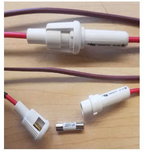
Memphis Fuse Diagram
Power Cable (VG1969) Fuse
- VG9021– Fuse Glass 250VAC 5A 5 x 20 mm
Logic Board Layout
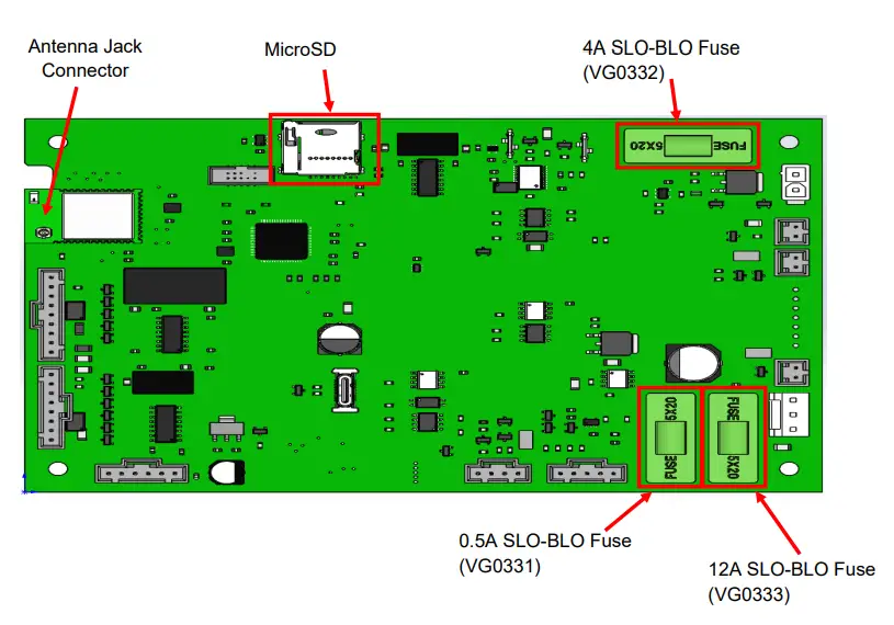
![]()


