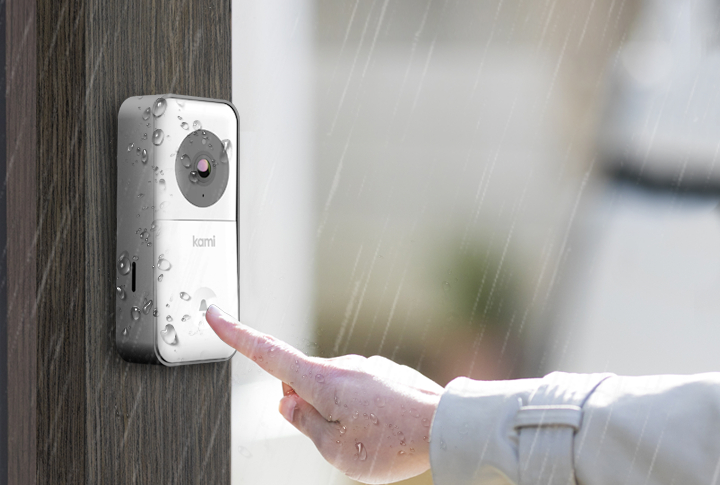
Kami YDS20121 Doorbell Camera
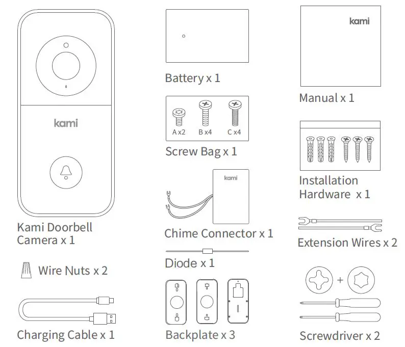
What’s in the Box
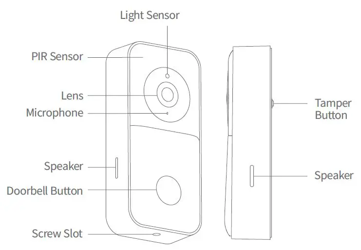
Getting to Know Your Doorbell Camera

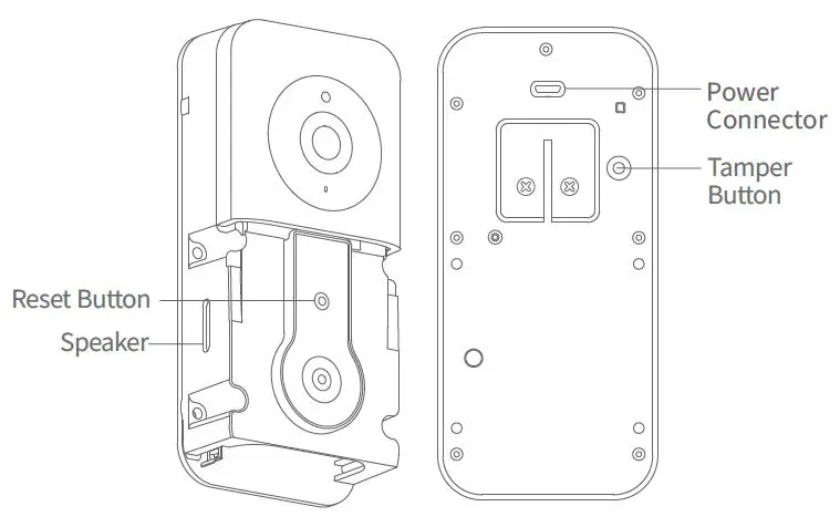
To reset the doorbell fast press the Reset Button (less than 1 second).
Charge + Insert battery
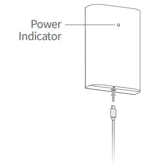
- Charge the Battery
Please charge the battery, using a micro USB cable. and a power adapter (not included).
The indicator light will be red while charging and turn white when fully charged.
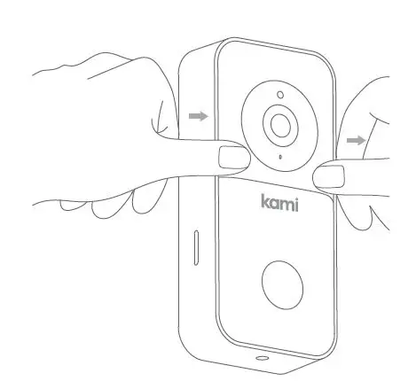
- Remove the Protective Cover
Press down on the face of the doorbell with your thumbs and pull the outer protective cover up and away from the main body, as shown in the diagram on the left.
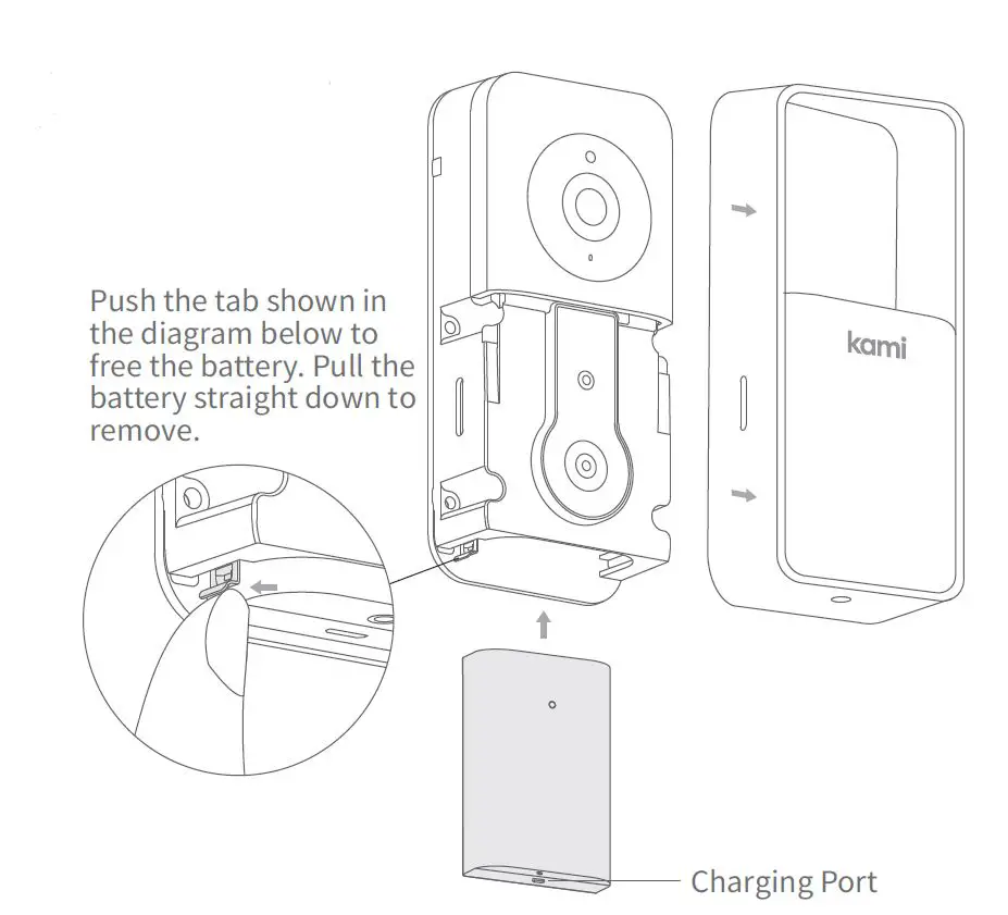
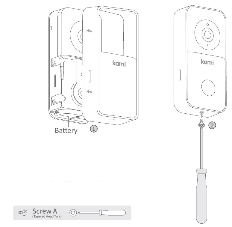
- Installing the Battery
After removing the protective cover, push the battery into the battery compartment as shown. (Ensure that the battery is inserted in the correct direction with pins facing up)
Pairing Your Doorbell Camera
- Step 1
Download the Kami Home / YI Home App and sign up or sign in to your existing account. - Step 2
Ensure that your cell phone is connected to your local Wi-Fi network. Enable the “Location” function on your phone, and then authorize the “Location” function of the Kami Home / YI Home App. - Step 3
After logging in to your Kami Home / YI Home App, tap the “+” symbol in the top right corner and select “Kami Doorbell Camera”. Wait for the voice prompt and then tap the “I heard ‘Waiting to connect’” button. - Step 4
Enter your Wi-Fi network password and tap the “Please choose Wi-Fi” button.
A QR code will appear on your phone’s screen. Point the QR code towards the camera lens until you hear the following voice prompts “QR code scan is successful connecting to Wi-Fi” and “Wi-Fi is connected”. - Step 5
Tap the “Next” button and wait until you hear the message “Pairing is successful” both from the camera and from the app. Assign your desired name to the Doorbell and tap “Save”. You will hear “You may start using your camera now”.
Installation Options
- Remove the Original Doorbell (optional)
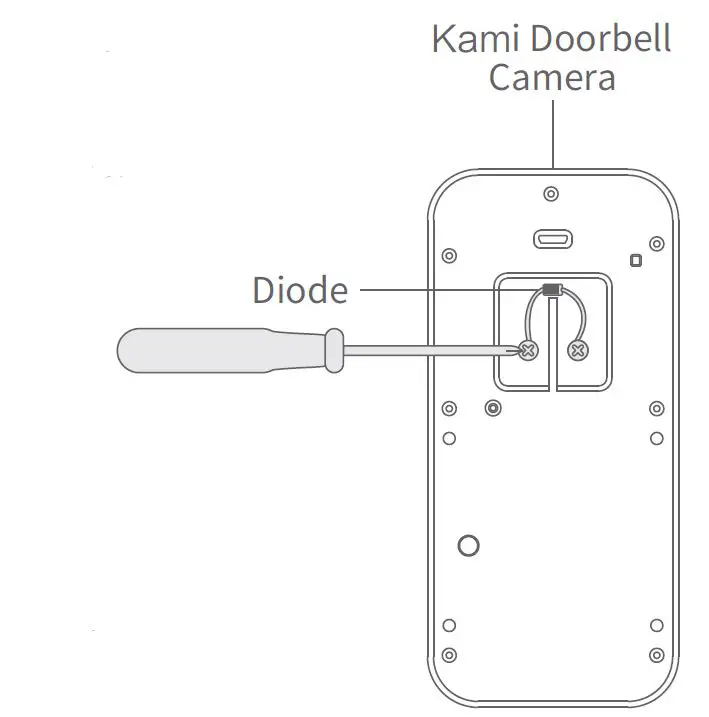
If you are replacing an eisting doorbell, please switch the power off, remove the doorbell, and disconnect the wires. - Electronic Doorbell Setup: Installing a Diode (optional)
- If you want to connect your doorbell to an electronic bell (if your doorbell has a speaker, it uses a digital chime), you will need to install a diode.
- If you are using a mechanical indoor doorbell, DO NOT install a diode, as this will damage the existing doorbell.

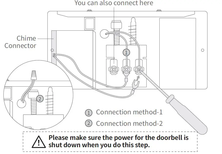
- Mechanical Doorbell Setup: Installing the chime connector (optional)
If you are using a mechanical chime, please install the chime connector 1 to ensure a stable power supply.
If you don’t want chime to make a sound, please connect the wires as shown in the picture 2 .
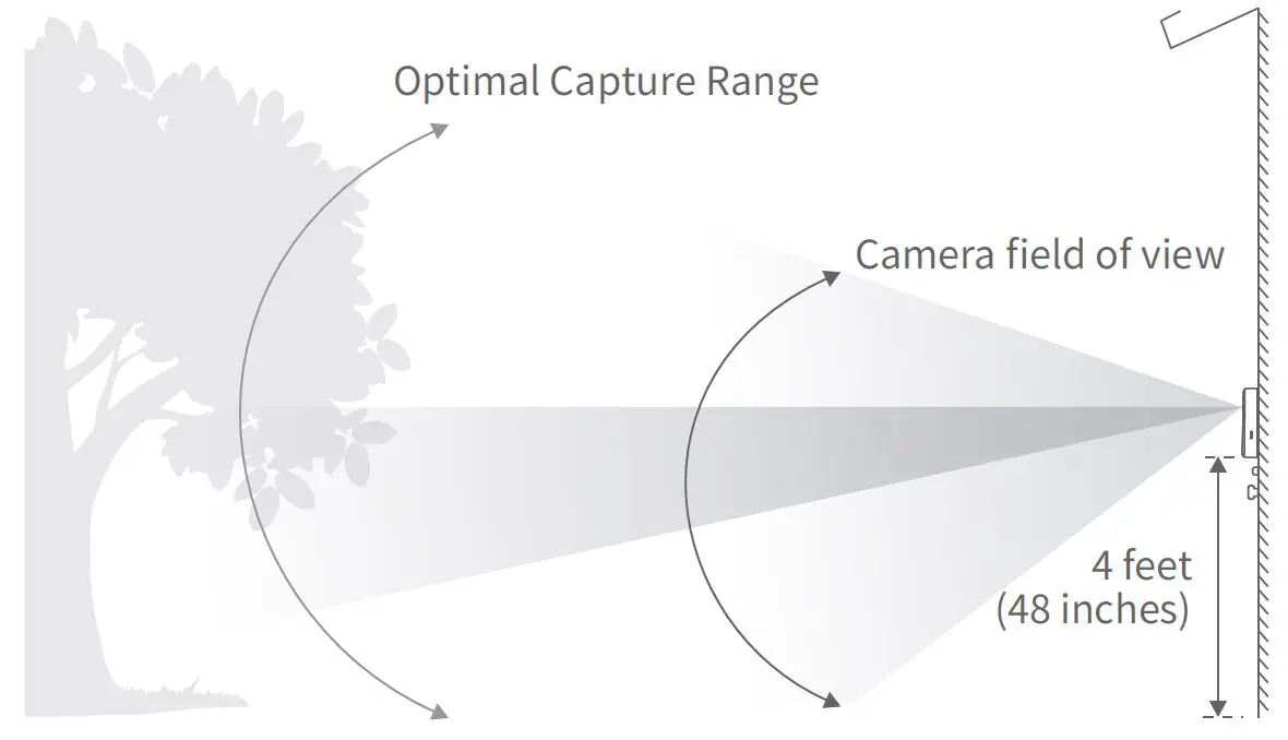
- Height and Distance Recommendations
The optimal detection range for the Kami Doorbell Camera is 0-4m / 0-13ft. Additionally, we recommend you install the doorbell at a height of 1.2m / 4ft to ensure the ground in front of your door can be captured.
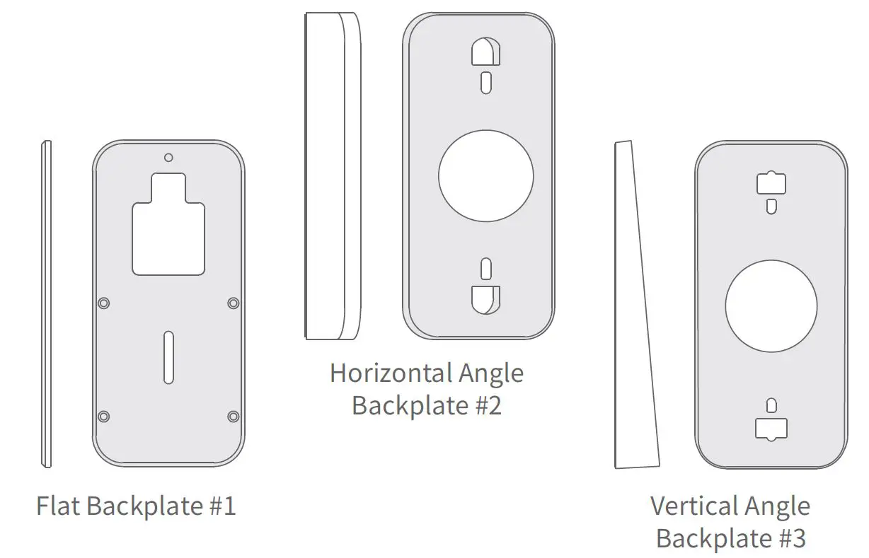
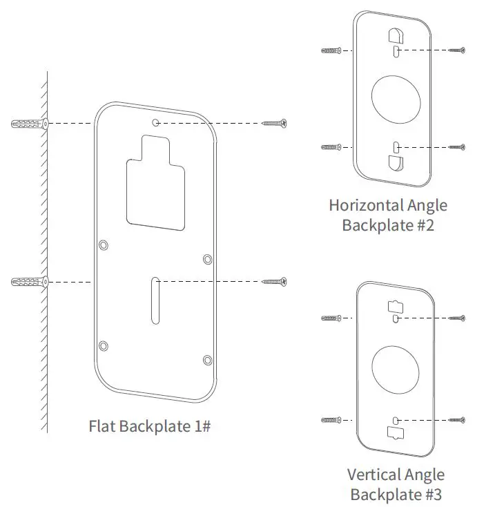
- Suggested Installation Angle
Your Kami Doorbell Camera comes with three different backplates that can be used to help place your camera at Flat Backplate #1.- If you don’t want to change the camera’s angle, use Flat Backplate #1.
- If you want to angle your Doorbell to the left or right, use Horizontal Backplate #2.
- If you want to angle your camera in a vertical direction, use Backplate #3.

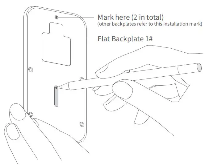
- Fixing the Backplate to the Wall (optional)
Take out the backplane and lay it flat on the wall where Doorbell is to be installed. Take a pen and press it firmly into the center of the two holes in the back panel to mark the wall.
Note: Installing your camera on wood doesn’t require screw anchors.

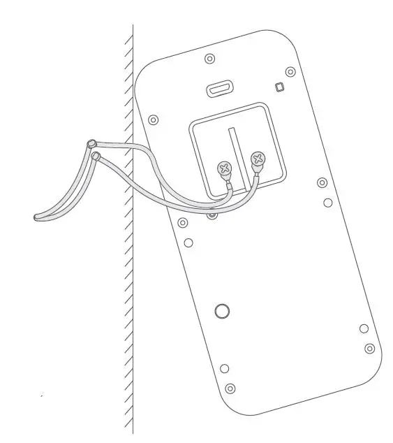
- Connecting the Doorbell wires and (2) Extension Wires (optional)
You connect each of the wires to either of the screws in the back. The order does not matter.
If your wires are too short and you have trouble connecting the wires coming out of the wall to the back of the doorbell, please use the included Extension
Wires and wire nuts. (See Picture) . CAUTION
Please make sure the power for the doorbell is shut down while you complete the wiring - Mount the Doorbell to the Flat Backplate
Feed all wires (and wire nuts, if you use them) into the wall and use four screws (screw C) to secure your doorbell to Flat Backplate #1.
Mount the Doorbell to the Flat Backplate: Mount the Doorbell to an Angled Backplate:
- Install the Front Panel
- Use Screw A to keep the Doorbell Front Panel in place.
- Use Mounting Screw A to fix the camera

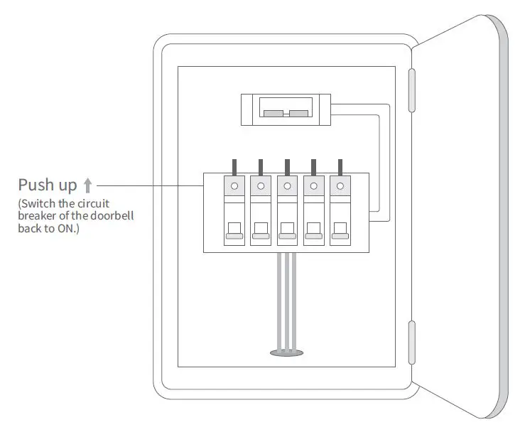
- Turning the Power On
To complete the installation process, please switch the power back ON and test the operation of your Doorbell.
 CAUTION
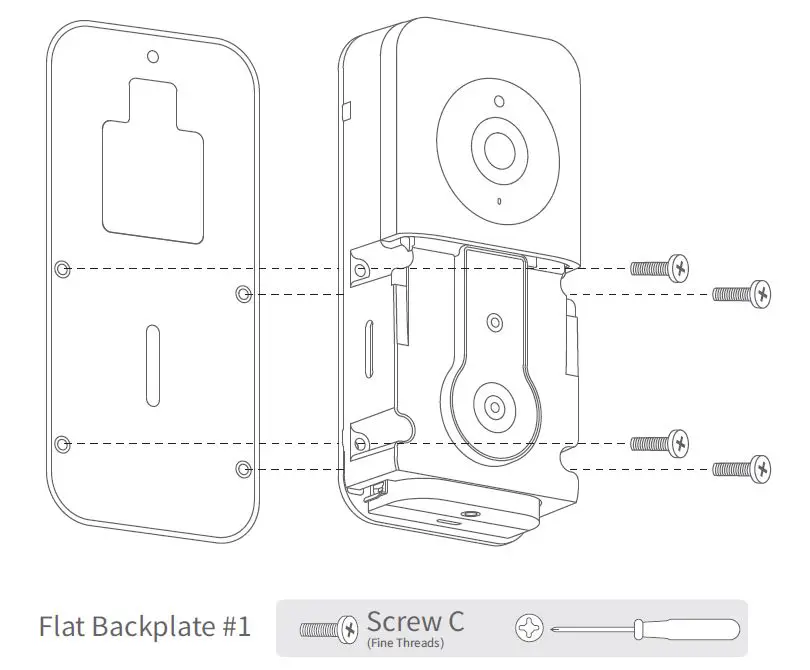 Mount the Doorbell to an Angled Backplate:
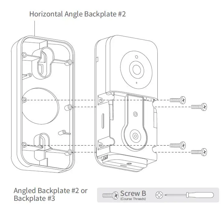
FCC COMPLIANCE STATEMENT:
This device complies with part 15 of the FCC Rules. Operation is subject to the following two conditions:
- This device may not cause harmful interference
- this device must accept any interference received, including interference that may cause undesired operation.
Changes or modifications not expressly approved by the party responsible for compliance could void the user’s authority to operate the equipment.
The distance between user and products should be no less than 20cm
This equipment has been tested and found to comply with the limits for a Class B digital device, pursuant to part 15 of the FCC Rules. These limits are designed to provide reasonable protection against harmful interference in a residential installation. This equipment generates, uses and can radiate radio frequency energy and, if not installed and used in accordance with the instructions, may cause harmful interference to radio communications. However, there is no guarantee that interference will not occur in a particular installation. If this equipment does cause harmful interference to radio or television reception, which can be determined by turning the equipment off and on, the user is encouraged to try to correct the interference by one or more of the following measures:
- Reorient or relocate the receiving antenna.
- Increase the separation between the equipment and receiver.
- Connect the equipment into an outlet on a circuit different from that to which the receiver is connected.
- Consult the dealer or an experienced radio/TV technician for help.
IC WARNING
This device contains licence-exempt transmitter(s)/receiver(s) that comply with Innovation, Science and Economic
Development Canada’s licence-exempt RSS(s). Operation is subject to the following two conditions:
- This device may not cause interference.
- This device must accept any interference, including interference that may cause undesired operation of the device
The distance between user and products should be no less than 20cm


