![]() Quick Start Guide
Quick Start Guide
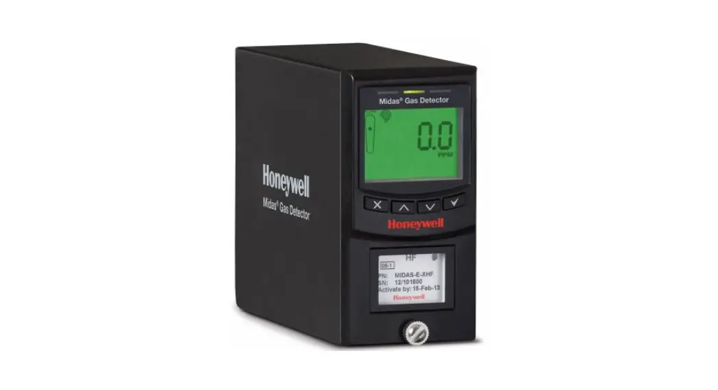
MDA Scientific Midas® Gas Detector![]()
Introduction
The Midas® gas detector is an extractive gas sampling system that draws a sample locally or from a remote point to a sensor cartridge that is located inside the detector’s chassis. A wide range of toxic, flammable and oxygen gas sensor cartridges are available that enable detection of gases used or generated in the Semiconductor and other manufacturing industries.
The Midas® gas detector is comprised of 4 main parts: the main chassis, the mounting bracket assembly, the sensor cartridge and the unit cover. Diagram 1 details the Midas® general arrangement. Additionally there are optional Pyrolyzer modules required for the detection of NF3 and PFCs and an optional LonWorks® interface is available.
This Quick Start Guide provides basic installation, setup and operation information for the main detector unit. For more detailed information on other features and options, please refer to the Midas® Operating Manual.
Diagram 1. Midas® general arrangement exploded view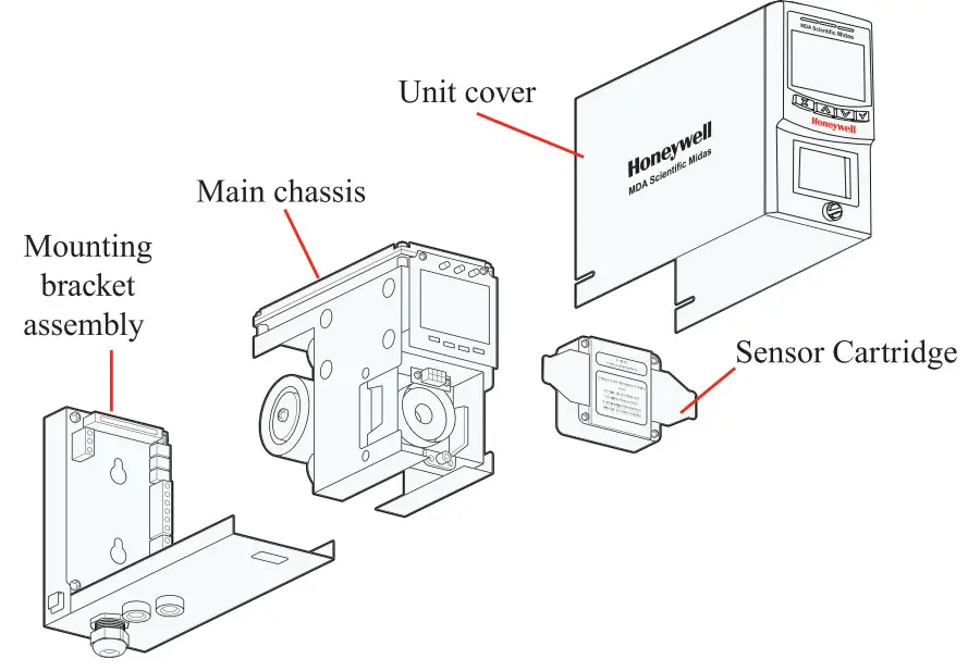
Mounting Details
The Midas® gas detector has an integral mounting bracket assembly that is easily mounted to a suitable vertical surface such as a wall, tool housing, mounting plate on a pole etc.
Drill Template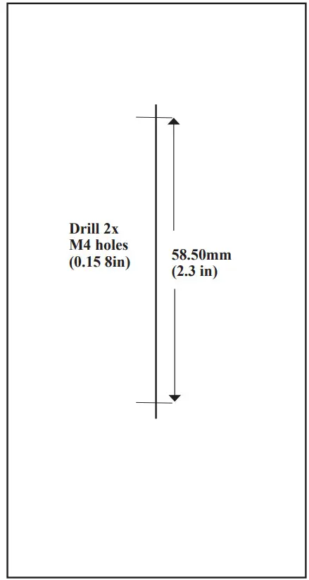
Note
When reproducing this diagram, be sure to check dimensional accuracy before drilling.
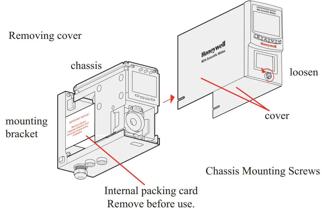
The following steps and diagrams show how to separate the mounting bracket assembly from the main chassis and mount it on a vertical flat surface.
- Unscrew the thumbscrew located on the front panel.
- Remove the cover by pulling it forwards off the main chassis. On new Midas® units, be sure to remove the internal packing card securing the pump. Failure to remove this packing will result in damage to the Midas® unit. (See diagram below)
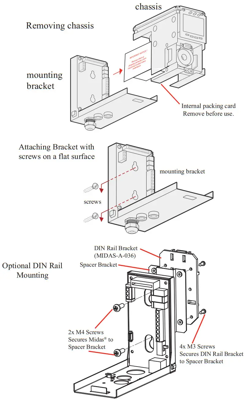
- Unscrew the two retaining screws located at the bottom front of the chassis.
- Holding the mounting bracket assembly with one hand use the other to carefully pull the main chassis forward to disconnect it from the mounting bracket assembly.
- Using the drill template provided drill two holes 2.3 in (58.50mm) vertically apart for 2 x round head M4 screws.
- Partially screw the fixings into the mounting surface.
- Place the mounting bracket assembly over the screws so they pass through the mounting holes and then slide down to locate in the slots.
- Tighten the screws to secure the mounting bracket assembly.
Diagram 3. Mechanical installation

Electrical Installation
Access for the electrical wires to the terminal module is made via the PG16 cable gland located at the bottom of the mounting bracket assembly. The cable gland can be removed and replaced with a suitable conduit fitting if required. The wire routing of a typical
installation is shown in the diagram below. 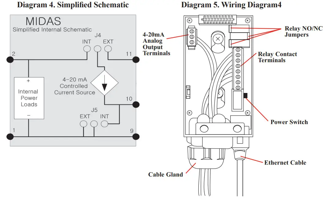
The terminals used are suitable for conductors of 24 to 14 AWG (0.5 to 1.8mm Dia.). The use of 16 AWG (1.5 mm Dia.) conductors is recommended.
If Power over Ethernet (PoE) is used to power the device, then 24 VDC power must not also be connected to the device, (or conversely if 24 VDC is used to power the Midas® , then electrical power via the Ethernet port must not be applied). Failure to observe this requirement may cause damage to the gas detection system and will not be covered by the standard warranty.
When connecting the wires ensure that the power switch is in the off position.
Refitting the Main Chassis
The main chassis can be refitted to the mounting bracket assembly using the following teps.
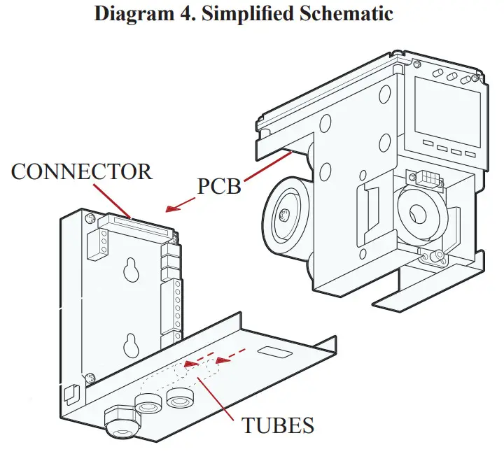
- Align the PCB at the top rear of the main chassis with the connector located at the top of the mounting bracket assembly
- At the same time align the two tubes at the bottom rear of the main chassis with the two tubes located on the bottom of the mounting bracket assembly.
- Slide the chassis backwards on the mounting bracket assembly so that the PCB and connector and tubes engage simultaneously. (See diagram below).
4. Ensure the PCB, connector and tubes are fully engaged by firmly pushing the main chassis horizontally backward on the mounting bracket assembly
(WARNING: DO NOT PUSH ON THE LCD AS THIS MAY CAUSE DAMAGE). - Align the two fixing screws located at the bottom of the chassis with the screw threads on the mounting bracket assembly.
- Tighten the screws to secure the chassis to the mounting bracket assembly.
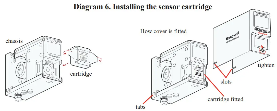
Installing the Sensor Cartridge
The Midas ® sensor cartridge is supplied separately and needs to be fitted to the detector’s main chassis. The following steps and diagrams detail the procedure for installing the sensor cartridge for the first time. This procedure is carried out with the power off and the detector cover removed.
- Verify the part number and type of sensor cartridge is correct for your application, then remove sensor cartridge from packaging.
- Remove cap from cartridge.
- Add label for secondary gases (if necessary).
- Align pins at the top of the sensor cartridge with the socket in the sensor cartridg chamber.
- Carefully push the sensor cartridge into the sensor cartridge chamber until fully seated.
- Lock the sensor cartridge in place using the tabs on either side of the sensor cartridge to secure the cartridge to the main chassis.
- Switch the power switch on the terminal module to the ‘on’ position.
- Reattach the detector cover by aligning the slots on either side with the locating tabs on the mounting bracket assembly.
- Push the cover horizontally until fully seated.
- Tighten the thumbscrew on the front panel.
 Note:
Note:
In a first-time start up, an F49 or F88 fault code may be displayed; there is no actual fault and the
fault message can be cleared by depressing the ‘X’ button for a few seconds.
To properly activate the Midas ® with a cartridge for the first time:
- When “ChAngE gAS” or “FIrSt CELL” scrolls on the display, hit the ‘3’ on the Midas ® front panel.
- When the “reboot” completes then press and hold the “X” to clear any latched fault(s).
- Confirm that the green LED is flashing.
- Confirm that the yellow and red LEDs are off.
- Confirm the display shows a concentration of zero (as appropriate).
The cartridge has now been accepted by the Midas ® as the correct type.
If the above steps were not performed at initial start-up, then remove the cartridge and cycle power.
Once the Midas ® has completed the “reboot” process, install the cartridge to be used and repeat the steps above.
Diagnostics
| Fault Code | Description | Condition | Recovery |
| m9 | Simubted Manta ranee Fault | User has generated a uvulas’ fault | Reset :flatbed faun |
| m10 | One range | A large concentration has been detected The tads regimes an independent conamabon that me gas hazard rs gone | Supply known dean am to the Midas and clear this fault |
| m11 | User cabman exceed | The user specified calibration interval has Ma pled. | Pedeern zero and span ea:brae:ins. reau |
| span cabman MVO | |||
| m12 | Cartridge eXpireS | Cartridge is o and we expire soon. | Replace me cartridge with a new cartridge |
| m13 | Pam haw | Midas’ is no longer able 10 regulate flow. | Cheri; Niers and ramp |
| mld | interteteM present. | An nterferent is decreeing the ability of the Midas* le detect gas. | Check aro . |
| m15 | Temperature near brnt | Temperature wain 2′ Celsius of font. | Check installation environment |
| mid | Baseline fault. | Sensor baseline has drifted. | temper-Check for beaground gas concernsabon. temper-Mule or humanly fluctuatens. Perform zero cabbratren. Replace cantata |
| m17 | Inaba flout. | ||
| Transmitter has been ri nate mode too bog | Resume manScong or increase fleet value. | ||
| F39 | Simulated Fault | User has generated a anblated fault | Reset stnulabd fault |
| F40 | Senses overdosed. | Sensor has been exposed to high gas concentra- Sons tor long periods. | Re e cartridge |
| Fd I | Bateau fast. | Sensor baseline has drifted. | Check for background gas concentration. temperature or hunakty fluctuatsre. Perform zero calibratun Replace carnage |
| F42 | Cabration eRerree | Too brig since Last calaratun. | Replace or calibrate the cartridge. |
| F43 | cartridge expired. | Cartridge Is too cid | Repose cartridge. |
| F44 | CH false | Cartridge has faded Reflex” check. | Replace cartridge |
| F45 | Stabilization bmeoul | Cartridge has faded to :Utilize | 11 temperature or humidity Sucks east. pteCOM14 bon the cartridge Check for background gas concentration. Replace curbed° |
| Fig | Cartridge analog Sure | Electra..< Failure Gas concentration greater than lull scale. | Re e cartridge |
| F47 | Carbldge merricrY Vivant | Checksum error. | Replace cartridge. |
| Fdll | Cartridge absent | No communications | Reseal cartridge Re01000 cartage. |
| F49 | Cartnciga wrong type. | Cartage type found to be ncorrect after 0001.Up. | Replace oartnigge Or press ‘1’ accept if erect |
| FM | letliperature beats | Ternperabre is outside knob | Check Installation vain:ems:et. |
| FBI | FlOW tall | Flaw < 10% of nominal for 15 seccals. | Check RIMS. Check for kekca Wheat Replace psT |
| Fa | Excessive °acmes noise | Check grounding of Midas* chassis. Check teMlinabOn of cable shields. Relocate the Midas° father from noise sowees. Add lernte inductors to cables. | |
| internal aectromcs repeatedly noisy | |||
| F83 | Pyrolyzer fail. | Pyrolyzer fails to heat. | Check electrical connection to pyrolyzer. Replace pyrolyzer. |
| F84 | Misc. transmitter fault. | Transmitter is defective. | Service or replace Midast. |
| F86 | Coprocessor fail | Coprocessor is damaged. | Contact Honeywell Analytics Service. |
| F87 | Pyrolyzer temp limits exceeded | Pyrolyzer temperature exceeded. | Clean pyrolyzer cooling vents. Contact Honeywell Analytics Service. |
| F88 | Pyrolyzer heater fail | Pyrolyzer heater failed. | Replace the pyrolyzer. Contact Honeywell Analytics Service. |
| F89 | Pyrolyzer power unreg | Target power not achieved within specified time span | If 24VDC power check, 21.6 < V in < 26.4 Contact Honeywell Analytics Service. Replace pyrolyzer. |
| F90 | Pyrolyzer heater mismatch | Requires High Temperature Pyrolyzer (MIDAS-A-HTP) | Contact Honeywell Analytics Service. |
| F91 | HTP module required | Check that MIDAS-S-CFX or MIDAS-E-CFX is installed for the high temperature pyrolyzer version | Change to HT Pyrolyzer |
| F92 | OP3 pyrolyzer module failure | Data value: 0x0800 OP3 pyrolyzer failed to get up to temperature | Replace pyrolyzer heater |
| Data value: Ox1000 OP3 pyrolyzer flow is out-of-range | Check flow connections between Midas and OP3 pyrolyzer | ||
| Data value: others OP3 pyrolyzer internal failure | Contact Honeywell Analytics Service. |
“Hot” and “Cool” messages are informational events that can be generated under two conditions:
- Immediately after the detector powers up.
- When the state changes from cool to hot or hot to cool.
“Hot” means the temperature inside the cartridge is at 40°C or above. “Cool” means the temperature inside the cartridge is below 40°C. In both cases the event data field will list the actual temperature at the time of the event.
Find out more
www.honeywellanalytics.com
Americas
Honeywell Analytics
405 Barclay Boulevard
Lincolnshire, IL 60069
Tel: +1 847 955 8200
Toll free: +1 800 538 0363
Fax: +1 847 955 8208
[email protected]
Europe, Middle East, and Africa
Life Safety Distribution AG(LSD)
Javastrasse 2
8604 Hegnau
Switzerland
Tel: +41 (0)44 943 4300
Fax: +41 (0)44 943 4398
[email protected]
Technical Services
[email protected]
www.honeywell.com
Asia Pacific
Honeywell Analytics Asia Pacific
#508, Kolon Science Valley (1)
187-10 Guro-Dong, Guro-Gu
Seoul, 152-729
Korea
Tel: +82 (0)2 6909 0300
Fax: +82 (0)2 2025 0388
[email protected]
![]()
honeywell
MIDAS-A-020 Rev 4.0
February 2013
© 2013 Honeywell Analytics


